FormaCars

Visit our community sponsor

Thanks Thanks:  0
Likes Likes:  0
Results 1 to 26 of 26

Thread: Front Tire Rub

  1. #1
    Senior Member
    Join Date
    Nov 2011
    Posts
    489
    Post Thanks / Like

    Front Tire Rub

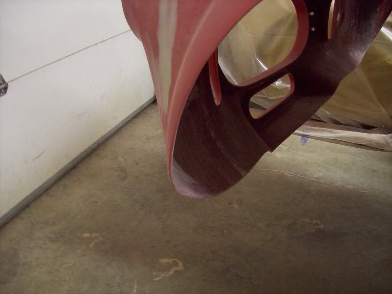
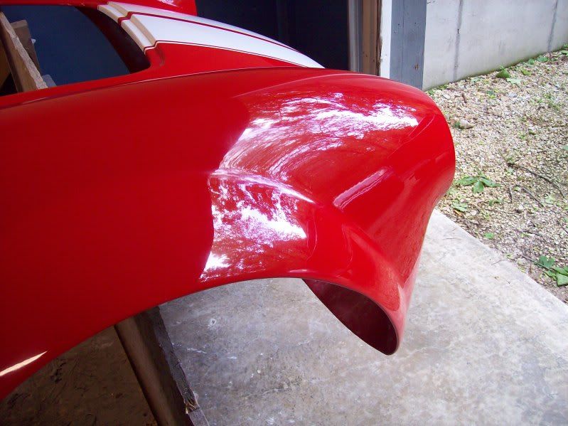
    It finally stopped raining here so I was able to get the car rolled out of the garage to take some pics for the insurance application. After I got it back in, I noticed the front edge of the left front tire was very close to the edge of the wheel opening. I turned the tire to the right and saw it actually rubbed and then saw a little of the paint was gone from the very inside lip of the wheel opening edge.

    The right front tire looks fine with at least 1/2" gap between the front edge of the tire and the wheel opening. I then measured the height of the center of the wheel opening (right over the center of the wheel) and saw that it was 27 1/2" on the right side and 26 7/8" on the left side so I guess that explains the gap differences. I then measured the distance from the bottom of the chassis to the floor and it was just about 4 1/2" on each side.

    I jacked up the right side of the car and removed the wheel so I could get access to the shock to make some adjustments. I turned the ring so that it would tighten against the spring to push the spindle downwards and increase the gap between the tire and body. I measured the distance from the ring to the top of the threaded sleeve before I started which was 2.5" so I figured I needed to adjust the spring at least 1/4" to get 1/2" height adjustment. The problem is that when I turn the ring, the spring and sleeve turn with it and nothing gets adjusted. The ring is tight against the spring and there really nothing to keep everything from turning.

    Do I have to put a spring compressor on the coil to create a gap between the spring and the ring so I can turn the ring?

    I'm using the SN-95 spindles if that has any bearing although if that was the issue, I would expect both sides to be off. Definitely the left side of the car is lower than the right.

    As always, thanks for your help.

    Ron

  2. #2
    Senior Member MPTech's Avatar
    Join Date
    Feb 2011
    Location
    St. Louis, MO
    Posts
    1,184
    Post Thanks / Like
    Blog Entries
    8
    Adjusting my shocks got tight the last couple turns too.
    I marked the shock with a small silver fine marker so I could tell 1/2 turn and full turn, then used a rubber strap wrench to hold the shock body and an allen wrench to turn the collar.
    F5R #7446: MK4, 302, T5 midshift, 3.55 Posi IRS, 17" Halibrands
    Delivered 4/4/11, First start 9/29/12, Licensed 4/24/13, off to PAINT 2/15/14!! Wahoo!

  3. #3
    Senior Member
    Join Date
    Nov 2011
    Posts
    489
    Post Thanks / Like
    Thanks, will try that. Yep, as soon as that ring got tight against the coil, everything turned. I tried to get a spring compressor on the coil but there's just no room around the control arms.

  4. #4
    Not a waxer Jeff Kleiner's Avatar
    Join Date
    Feb 2011
    Location
    Bloomington, Indiana
    Posts
    8,077
    Post Thanks / Like
    A few thoughts Ron but first---I saw your photos in the other thread and the car looks fantastic!

    Regarding rub; is the car aligned yet and which SN95 spindles are you using? If you haven't aligned it yet you may find that once you have ~1/2 degree negative camber the top of the tire will come inward enough that there is not an issue. There are two types of SN95 spindles. 1996 and later move the wheel/tire outward approximately 3/8" farther than 1994 & 1995 versions. Many other builders have experienced front tire clearance problems with the later spindles. The '96 and up can be identified by their straight steering arm vs. the "dogleg" arm on the '94/'95. If you have the later spindles you might be able to alleviate part of the problem with a little more negative camber, say up to a full degree. Increase in tire wear should be minimal.

    I've not had a problem turning the adjuster rings even with light spring pressure on them as you describe but like Mark others have reported that a strap wrench around the collar helps. Be sure that the adjuster ring locking setscrews are not tight. After you assure that they're loose take ithem out and throw 'em away! With the car's weight on the springs they do not turn and all the setscrews do is booger the threads making it difficult to turn the rings. BTW, you don't have to remove the wheel to make spring adjustments. Raise the car and support the chassis then by turning the wheels to full lock (right to get to the right side and vice-versa) you can get to the spring by reaching in front of the tire.

    We all know that the bodies are not symmetrical so when setting ride height go by the chassis, not the body or wheelwell opening. Be careful when making adjustments because what you do to one corner affects the diagonally opposite corner (i.e.; RF acts upon the LR). For example if you tighten the collar to raise the RF it will drive the LR down. I always work diagonally when making ride height adjustments. Once set properly you should have virtually the same amount of threads showing left to right although not necessarialy front to rear depending on ride height.

    Hope some of that helps and good luck!

    Jeff

  5. #5
    Senior Member
    Join Date
    Nov 2011
    Posts
    489
    Post Thanks / Like
    Many thanks Jeff.

    The spindles came off a 1995 car and do have the doglegs so that shouldn't be an issue.
    I did have the front end aligned in the go kart stage so that's done also.
    Followed a previous post and removed all of the set screws from the rings and put them in my miscellaneous screw drawer.

    Will try Mark's advice and put a strap wrench around the threaded sleeve to see if that will hold it while I turn the ring.

    The rear of the body is pushed all the way up to the lower trunk panel so there's no way I could have gained more wheel clearance that way if you know what I mean.

    Really not sure why I am having this issue. I made up some blocks that are 4.25", 4.5" and 5" tall to use to measure chassis height. As I mentioned, the ride height as measured at the chassis is pretty much the same but still have this interference on the left wheel. Increasing the spring pressure to push the left wheel down to increase the clearance seems to be the only way to correct.

    Will work on it again this afternoon.

    Ron

  6. #6
    Senior Member
    Join Date
    Nov 2011
    Posts
    489
    Post Thanks / Like
    Just wanted to post an update.

    As it turned out, a little WD40 on the sleeve threads was all that was required to turn the shock adjuster ring however this didn't fix my problem. Raising the ride height on the left side only did so much.
    Measured the length of the arms on the UCAs and found a 1/2" difference between left and right front arms so changed the left arm to be same length as right (lengthen it) which did move the top of the spindle back and helped center the wheel. I realize that I just ruined my front end alignment but I can easily get that done again. However, my concern is now that for the alignment guy to get the camber/caster set, he will have to move the spindle back to where it was and I will have the clearance issue again.
    As I have the UCA adjusted now, both front wheels appear to have the same amount of clearance in the wheel wells and are pretty much centered (note the right wheel was fine as is) but there must be something with the steering geometry. Both tires have about 1/2" clearance between the front edge of the tire and the wheel opening. If I turn the wheels to the left, the right tire turns into the wheel opening with just about the same 1/2" clearance. If I turn the wheels to the right, there is barely 3/16" clearance between the front edge of the tire and wheel opening. This is on the flat and level garage floor but if I was on the road and there was any type of bump, the tire would hit the body.
    One option is to switch out the 245 tires I have on the front with 235 ones but according to the tire specs that will only give me an additional 1/4" of clearance per side. If there was an issue with both sides, this would be something to consider but that's not the case.....it's a left side issue only.
    I have measured the body in 6 or 7 locations and there is no issues there. Side to side measurements are within 1/8". The body is pushed as far forward as is possible so can't pick up any clearance there.

    Thoughts?

    Ron
    Last edited by SCFFR; 07-09-2013 at 05:56 AM.

  7. #7
    Senior Member
    Join Date
    Nov 2011
    Posts
    489
    Post Thanks / Like
    Was able to get some pics taken today. Here is the right side of the car. Wheel is properly centered in wheel opening. You can see the orientation of the spindle which has been adjusted to the correct alignment specs. Two pics show clearance at the front edge of the tire when the wheel is straight ahead and when it is turned to the left. The clearance stays pretty much the same.
    RHSpindle.jpgRHWheelClearance.jpgRHTireEdgeClearance.jpg

  8. #8
    Senior Member
    Join Date
    Nov 2011
    Posts
    489
    Post Thanks / Like
    Here is the left side of the car. Wheel is forward in the wheel opening. I discovered that the front arm on the LH UCA was 1/2" shorter than corresponding arm on RH UCA so adjusted to make both the same. You can see the caster on the spindle has been greatly increased (it was +3 degrees before I changed it). Two pics show clearance at the front edge of the tire when the wheel is straight ahead and when it is turned to the right. The clearance decreases to the point it rubs the inside edge of the wheel opening.

    Are the FFR tubular LCA the same, i.e., are they left or right handed? I was under the impression that they are not and either can be mounted on either side.

    Still have no clue on how to fix.

    Thanks,

    Ron
    LHSpindle.jpgLHWheelClearance.jpgLHTireEdgeClearance.jpg

  9. #9
    Not a waxer Jeff Kleiner's Avatar
    Join Date
    Feb 2011
    Location
    Bloomington, Indiana
    Posts
    8,077
    Post Thanks / Like
    Ron and I have been talking both via PM as well as by phone. The issues are a little puzzling and my gut feeling is that his original alignment was off. It would be very unusual for the threads exposed on the UCA adjuster tubes to vary by as much as 1/2 inch if the two sides were set for the same caster and camber. The lower control arms are not side specific and indeed can be mounted on either side. With that said the photos do show a couple of things:

    #1. Those are PBR dual piston brake calipers which were not used on the Mustang until 1999. Unless your spindles have been modified to accomodate them I believe you don't actually have '94/'95 spindles and in fact have '99 or later versions which put the wheel/tire assembly ~ 3/8" farther out. Take a look at this photo which shows a '94/'95 spindle in the rear and a '96 and later unit in the front:


    Note that the '94/'95 has a "dogleg" in the steering arm (where the tie rod attaches) while the later version is straight. Take a look at yours and report back on what you find. If yours have the straight arm they are later spindles and the wider track they create would definitely be a contributing factor to your issues.

    #2. Your fender lip return is not cut back much. Take a look at how I finished out the front wheelwells of a Mk4 by removing almost all of it and then rolling the lip:


    Needless to say if yours were relieved further it would provide additional clearance when the wheels are turned.

    Again, I really believe that flawed alignment is the root of your problem but it is being exacerbated by the combination of wider front tires, the possibility of a wider track created by late model spindles, and the extra material left in the wheel opening.

    Keep us posted and good luck!

    Jeff

  10. #10
    cobra Handler skullandbones's Avatar
    Join Date
    Jul 2011
    Location
    Superstition Mtn foothills 5 miles west of Gold Canyon AZ
    Posts
    2,686
    Post Thanks / Like
    Blog Entries
    19
    Hi Ron,

    I noticed you are running the FFR adaptor so you have not done the SAI mod. I saw a video where Breeze is moving the lower control arm in the other hole and re-positioning the upper control arm (installing it under the spindle bracket instead of on top). In that video they modify the frame rail by cutting out about 40% of it which I didn't particularly like. So I figured a way to do that mod without cutting the 3/4 inch frame rail. It involves installing a couple of steel wedges on the forward bolt of the spindle which supports the spindle and allows for correct angles for the flat of the bolt and nut. So in conjunction with the SAI mod, you can improve your steering geometry and move the wheel in by the distance of that hole difference on the lower control arm bracket. It also requires some longer upper control arm pieces that you get from Speedway or others as well. Right now I am mocking mine up to see how it fits so I'm not sure exactly which combination of control arm pieces I will need to place the upper ball joint in the right position. Mine may be a little different since I am working to get about 6 degrees of castor for this setup (power steering). If you didn't have PS, you would want a little less castor if you have a manual rack but whatever added castor you decided on would help alleviate the problem you describe above. I don't have any pics as of yet but I will pretty soon. BTW, I am using 2000 GT spindles for the big brake mod but they are wider than yours and it still should work. If I had done better research, I would have probably gotten the 94-95 spindles. Anyway, I just thought I would put that bug in your ear so to speak, if you can not find a feasible resolution. Hope you do, Good luck, WEK.
    FFR MkIII 302 (ATK), EFI 75mm TB with custom box plenum chamber, 24# injectors, 4 tube BBK ceramic, cold air sys, alum flywheel, crane roller rockers, T5, Wilwood pedals, custom five link with Watt's link, 4 rotors, coil overs, power steering with Heidt valve, alum FFR rad, driver's crash bar mod, mini dead pedal mod, quick release steering wheel hub #6046

  11. #11
    Senior Member
    Join Date
    Nov 2011
    Posts
    489
    Post Thanks / Like
    Again, thanks for the feedback.
    Have attached a pic of the spindles so we can check that off the list.
    Jeff and I had talked earlier about the wheel lip and I guess I thought I had taken most of it off but was obviously wrong on that point. I can certainly open that up some more.
    I guess the confusing part of this problem is that the wheel on the right side is perfectly centered and turns without any clearance issues. If I had installed a part incorrectly or used the wrong ones, it would have affected both sides which is not the case. Although I didn't cut the wheel lip back entirely, it's the same on both sides (I used a guide I had made).
    I decided to bite the bullet and getting the front 245 tires replaced with 235's this morning. Will see how much of a difference that will make. As Jeff and I discussed, I can't expect to see more that 1/4" of extra clearance on the front edge of the tire but if I take some more of the lip off, I might be where I need to be.

    Again, many thanks for your help and feedback.
    Will look into your version of the SAI mod. I definitely don't want to cut into the frame.................
    Ron
    Spindle.jpg

  12. #12
    Not a waxer Jeff Kleiner's Avatar
    Join Date
    Feb 2011
    Location
    Bloomington, Indiana
    Posts
    8,077
    Post Thanks / Like
    Ron,
    Coincidentally a thread regarding wheelwell cutting and shaping was just resurrected on the other forum.

    http://www.ffcars.com/forums/17-fact...well-lips.html

    I still think alignment error is the main culprit though, specifically insufficient positive caster on the left side.

    Cheers,
    Jeff

  13. #13
    Senior Member
    Join Date
    Nov 2011
    Posts
    489
    Post Thanks / Like
    Thanks again Jeff.

    There was definitely something whacky with the UCA on the left side. I think you are spot on with regards to a wrong caster setting. I don't see how the setting could be the same on both sides if the UCA arm lengths was that much different.

    Took advantage of the down time to coat my splash panels with bed liner. Originally was going to get them powder coated but if you notice from my pics, I have a gravel driveway so I thought the bed liner would last longer and cut down on noise. Will get the front ones installed today while I have to front wheels off and can then see how the new tires fit.
    Also dyed the door straps black to match the rest of the interior. Found a small bottle of KIWI leather dye at WalMart and did them yesterday. Turned out great and the dye was less than $5.
    If you are interested in a pair of Cooper Cobra GT 245/60-15 tires with less that 100 feet (yes that's feet not miles) on them, send me a PM.

    Thanks again for all the help. Hopefully the combination of tires, additional work on the wheel opening, and proper alignment will get me road ready.

    Ron
    RearSplashPanel.jpg

  14. #14
    Senior Member
    Join Date
    Feb 2011
    Location
    Myrtle Beach, SC
    Posts
    2,108
    Post Thanks / Like
    Hey Ron-

    Please be sure to let us know how the tires and re-alignment work out! I think Jeff is on to something here...

    Splash panels look great!

    Best of luck, and I will continue my head-banging!!

    Regards,

    Steve

  15. #15
    Senior Member
    Join Date
    Nov 2011
    Posts
    489
    Post Thanks / Like
    Update:

    Just wanted to post an update in regards to the issue I am having with the front tire rub on my LF wheel.

    Here's what I have changed/done since my first post.

    Replaced the Cooper Cobra 245/60-15 tires with 235/60-15 ones.

    Measured and adjusted the UCA arm lengths on the left side to be the same as on the right side where the wheel is perfectly centered and no clearance issue when turning the wheel. Note that the front end will have to be aligned again but I would assume that by making the UCA arms the same, it will be close. If not, wouldn't that mean that the bottom pivot point of the spindle is off?

    Removed some more of the edge of the wheel opening lip in the area at the front of the tire but not going to remove any more until alignment is done.

    Results: When I turn the wheel to the right, the space between the tire and wheel lip is about 1/4". Better than before but this is on a flat level surface. With any bump in the road, the tire will hit the wheel opening.

    I have been focusing on the tire and the front edge of the wheel opening so started looking at the space between the rear of the tire and the wheel lip. There appears to be almost a 1" difference from side to side. For example, if I measure from the thread surface to the front edge of the mounting flange (MkIV only) the RF tire is 1" closer than the LF. I realize that the body isn't perfectly symmetrical but this seems to be too much of a difference.

    I guess what has me puzzled about this whole situation if that the RF wheel is perfectly centered with plenty of clearance when turning. The amount of material taken out of the wheel well is exactly the same on both sides. It's almost like the LF side of the body needs to move forward which is obviously impossible. Since the LCA's are the same and assembled in a jig, I think I can rule out that the one I have installed on the left side is a little off but it's not off the table. Is there any reference point on the chassis where I could measure to the lower ball joint to compare left versus right?

    The next thing on my list is to get the front end aligned again. I will mention to the mechanic the problem I'm having with the tire clearance and see if he has any suggestions. The first alignment was done on the go kart so wheel clearance was not a consideration. The spindle can be pivoted rearward to get the wheel more centered but as I showed in pics, the caster would be way off.

    On a more positive note, finished up installing the rest of the splash panels. No real problem but I did have to widen the middle part of the front panels to make them wide enough so the bulb seal would actually contact the body. If would be nice if FFR would go ahead and make these a little wider so the builders wouldn't have to do this modification. It's so much easier to trim one that is a little big than to add material to one that's too small.

    Also have posted a pic of the installed dyed door strap. The leather dye worked great and looks so much better.

    Just wanted to thank everyone again for their continued help in resolving the issue.

    Ron

    LFWheelClearance.jpgLFWheelClearance2.jpgRFSplashPanel.jpgDoorStrap.jpg

  16. #16
    Senior Member CraigS's Avatar
    Join Date
    Feb 2011
    Location
    Blacksburg, Va
    Posts
    4,730
    Post Thanks / Like
    A couple of thoughts for you. The fender lip as is really hurts steering angle/tire clearance especially in the front. I am not sure why FFR makes them like this as it really looks like they plan for that extra edge to be left there. The previous bodies didn't have such a defined extra lip so it was pretty obvious that what was there needed to be removed. I think you will be able to carefully remove near all of it and then use a touchup stick on the edge. It will be turned under so not too visable.
    I am concerned why the suspension seems to be so different side to side. I suggest putting the car up on jack stands and laying under there w/ a tape measure. try to figure a reference point to see if the lower ball joints are in the same position front to rear.
    Regarding the UCA, the MkIV makes this a little harder since the x frame in front is now round tube but here is my technique for a rough check of caster. W/ the car on jack and the front wheels removed, lay a yardstick or similar horizontal on the front edge of the vertical 2x2 so one end sticks out toward the UCA ball joint and the other end sticks inward along the surface of the X frame. Try to find a position of the inner end of the stick that can be repeated on the other side. then measure from the edge of the stick to the UCA ball joint. Hopefully both sides are the same or very near the same. I am hoping that you have made them equal and that the alignment guy simply made a mistake setting one side to +caster and the other side to -caster.
    FFR MkII, 408W, Tremec TKO 500, 2015 IRS, DA QA1s, Forte front bar, APE hardtop.

  17. #17
    Senior Member
    Join Date
    Nov 2011
    Posts
    489
    Post Thanks / Like
    Many thanks Craig.

    I just crawled out from underneath the car trying to measure the position of the LCA ball joint to a point on the chassis. I also looked at the location of the LCA brackets on both sides. In both cases, L and R appear to be the same.

    I left a little of the inner edge on the wheel openings since it does give it a little more strength.........maybe that's really not important. Its like taking a flexible piece of sheet metal and putting a bend in it.................makes it more rigid.

    Regardless of the lip issue, there is just something off. It is possible that the mechanic got the caster setting wrong but if so, hopefully only on the left side. The right is perfect.

    Question - to help center the left wheel, I need as much positive caster as possible to lay the top of the spindle back towards the rear of the car (I think "positive" is right).
    What is the maximum caster angle I can safely have on my car? MkIV with manual steering and 1995 dog leg spindles.
    I had instructed the mechanic to set the caster at 3 degrees. Assuming the right spindle is correct, additional caster won't impact the wheel location but will certainly help get my left wheel more towards the center of the wheel opening.

    Many thanks again,

    Note: edited this post to add some more information. After posting, went back to the garage and stared at the car for a few minutes. I then got the idea to measure the distance between the centers of the front and rear ends, i.e. the wheelbase. Assuming that the rear end is the fixed point (I have 3 link setup), I got the following values:

    Right side: 89.75 inches
    Left side: 90.25"

    Again, since I have no issues with the right front wheel, I am assuming the caster/camber was properly set. That being the case, the center of the left side spindle is 1/2" further forward than the right side.............thus causing the wheel clearance problems I'm seeing. Of course, I had adjusted the left UCA arms when I discovered the front one was 1/2" shorter that the corresponding one on the right UCA so the caster/camber on the left side is shot. So I guess the next thing is to get the front end aligned again. I will have the mechanic measure the setting on the right side again to confirm the 3 degrees positive caster and 1/2 degree negative camber. I will then have him adjust the left side to the same settings and look at how the wheel is centered. Hopefully, he blew it the first time and that was the cause of the wheel being too far forward. If that is not the case, I will have him set the caster to the max I can safely use (whatever number I get from other members) and hope that will center my left wheel to at least somewhat match the right side. I have to admit, if this doesn't fix the problem, I'm at a complete loss.

    Ron
    Last edited by SCFFR; 07-12-2013 at 10:47 AM.

  18. #18
    cobra Handler skullandbones's Avatar
    Join Date
    Jul 2011
    Location
    Superstition Mtn foothills 5 miles west of Gold Canyon AZ
    Posts
    2,686
    Post Thanks / Like
    Blog Entries
    19
    Hi Ron,

    It feels to me like you may be chasing a moving target. You said you measured the wheelbase and got the 0.5 inch variation. I have heard that generally speaking you should not measure using the frame rails as a reference (in my reading about suspension setups). However, with the FFR 4 inch tubular frame rails, I think you could make an exception. So here is what I would do and by the way I am doing this on mine to verify some measurements. Get a long straight edge. I have an 8 foot one that I am using. Place it across the frame rails underneath and anchor it with blocks or something to hold it in place. take a square and square it to each side frame rail and then anchor it so it is steady. Then take measurements from those marks on the frame rail. I would measure between the reference mark to the edge of the LCA bracket and also to the lower ball joint. If those measurements are the same side to side, you probably have a measurement error or rear end position difference that you somehow missed. You could use that reference point to measure to a point on the 3 link as well. It is unlikely that the LCA bracket is misplaced since they use a jig to weld those up. What I'm getting at is you may not have a variation in the location of the front suspension at all. If that is the case, you can get your front end aligned and add castor if you wish for extra spacing (say 4 to 5 degrees). Then you will know that any variation you have in that area is due to the body positioning and maybe molding variance not your suspension. If you had a 4 link I wouldn't be concerned as you don't have any choice in the setup but with a 3 link it can look OK and still be off some. Also, it is infinitely adjustable. Hope this helps and I apologize if you have already done this. I was just thinking it could be a possibility. Thanks, WEK.
    FFR MkIII 302 (ATK), EFI 75mm TB with custom box plenum chamber, 24# injectors, 4 tube BBK ceramic, cold air sys, alum flywheel, crane roller rockers, T5, Wilwood pedals, custom five link with Watt's link, 4 rotors, coil overs, power steering with Heidt valve, alum FFR rad, driver's crash bar mod, mini dead pedal mod, quick release steering wheel hub #6046

  19. #19
    Senior Member CraigS's Avatar
    Join Date
    Feb 2011
    Location
    Blacksburg, Va
    Posts
    4,730
    Post Thanks / Like
    The problem I see w/ trying to measure the wheelbase is the steering. If the front wheels are off center even a small amount they move quite a lot for and aft. that makes measuring wheel base difficult. RE; caster. Most seem to say you can safely go to about 5 degrees, ans still have enough thread engagement. But, w/ manual steering, you don't want more than about 3 deg. or the steering will need too much effort.
    FFR MkII, 408W, Tremec TKO 500, 2015 IRS, DA QA1s, Forte front bar, APE hardtop.

  20. #20
    Senior Member
    Join Date
    Nov 2011
    Posts
    489
    Post Thanks / Like
    Many thanks again for the information and suggestions. Much appreciated.
    Will try the measurement setup you mention and see what kind of numbers I get but as you state, the frame is jig built so I don't expect anything to be off. I had already measured the position of the LCA mounting brackets and found them all to be exactly the same.
    I realize that my wheelbase measurement is not the most reliable. I guess I figured that since the LCAs on the rear end are fixed in length, I would measure from the rear axles forward. I had adjusted the UCA arm lengths on the left side to be exactly the same as on the right and had centered the steering. Obviously, everything was "ballpark" at best. I shouldn't make any assumptions until I get the front end aligned again which I will try to get done next week whenever it stops raining around here.

    Have a great weekend,

    Ron

  21. #21
    Not a waxer Jeff Kleiner's Avatar
    Join Date
    Feb 2011
    Location
    Bloomington, Indiana
    Posts
    8,077
    Post Thanks / Like
    Quote Originally Posted by SCFFR View Post
    ....I shouldn't make any assumptions until I get the front end aligned...
    Winner, winner chicken dinner

    Jeff

  22. #22
    Senior Member
    Join Date
    Feb 2011
    Location
    Myrtle Beach, SC
    Posts
    2,108
    Post Thanks / Like
    Ron-

    Please update us after the alignment (round two). I hope you find that to be your answer!! Good luck!

    Regards,

    Steve

  23. #23
    Senior Member
    Join Date
    Nov 2011
    Posts
    489
    Post Thanks / Like
    Will do Steve. Hope to get that done weather permitting.

    If that is the problem, everyone gets a chicken dinner!!

    I have to admit that I miss working on the car every day. Once the wheel rub issue is resolved, the car is finished. All I got accomplished yesterday was to get the side mirror installed. I guess its time for another project.

    Ron

  24. #24
    Senior Member CraigS's Avatar
    Join Date
    Feb 2011
    Location
    Blacksburg, Va
    Posts
    4,730
    Post Thanks / Like
    Ron I bet it's not done. I hope you have located a local group of Cobra guys in your area. The guys and galls make this a lot more than just a car deal. I suspect that you will see other cars and find other stuff to do.
    FFR MkII, 408W, Tremec TKO 500, 2015 IRS, DA QA1s, Forte front bar, APE hardtop.

  25. #25

    Join Date
    Feb 2011
    Location
    Norton, MA USA earth
    Posts
    3,345
    Post Thanks / Like
    Ron. Did you ever get this resolved? I have a very new Mark 4 here with the exact same problem. Right side is perfectly centered, left side rubs hard when trying to turn.
    mike

  26. #26
    Senior Member
    Join Date
    Nov 2011
    Posts
    489
    Post Thanks / Like
    Hey Michael,

    Unfortunately I never got my issue resolved. I contacted FFR with my problem and the measurements I had taken with the wheel clearance and differences in wheelbase. They checked all of their LCAs that had in stock and told me that they were all the same. At that point my options were to replace the front tires again with a smaller size or see if I could find some adjustable LCAs but haven't done either. The clearance I got from going to a smaller front tire made the car driveable but embarrassed to say that I have only driven the car about 200 miles in the last year mainly due to starting a new project. I have come to realize that I enjoy working on a project more than actually driving it after it is finished.

    I found a 1968 Mustang fastback on eBay and now in the final stages of a complete resto/mod project to make a Steve McQueen Bullitt replica. Bought a new Ford Racing 427 crate engine from Mike Forte which looks great in the engine compartment. Hope to have it on the road in a few months.

    Ron

Posting Permissions

  • You may not post new threads
  • You may not post replies
  • You may not post attachments
  • You may not edit your posts
  •  

Martin's Dent and Collision Shop

Visit our community sponsor