-
05-08-2015, 02:56 PM
#161

Originally Posted by
TouchStone

Can you send me the google spread sheet or excel file of this document. I want to integrate pictures directly into this document, and make notes for a 2003 WRX Wagon.
I just saw this. PM me your email and I'll send it to you.
-
05-08-2015, 03:12 PM
#162
Senior Member

Thanks for the quick replies, guys!
Kit #295 Picked up 11/26/2014!
-
05-08-2015, 03:19 PM
#163
Senior Member


Originally Posted by
matteo92065

Its the daytime headlight dimmer. You can look it up in the FSM as connector "B5", "Daytime Running Light Resistor".
Funny thing is you can find them on Ebay listed as Fuel injection components.
Edit: What to do with it? I kept it, and installed it. Or you can jumper the wires and your DRLs will not be dimmer during the day.
It will not work unless you keep the "Daytime Running Light Control Module" (B96) that controls the "Daytime Running Light Relay" (B102).
Dang it. I never even checked that against the wiring diagram but you are absolutely correct. I would have jumpered past it. Oh well, kept it in place because the internet told me it was related to the fuel injection system (that's what pops up when you google the part number on it). Think of the grams I could have saved! Rasmus would be very disappointed in me right now. Guess I have a winter "project" for next year.
-
07-02-2015, 10:15 AM
#164
bump for an amazingly helpful thread!!
-
07-02-2015, 11:42 AM
#165
Senior Member
It seems so long ago, that I was studying this thread.
When I first started going through the harness, I took all of Craig's pictures and put the plug numbers and his comments on the picture. It was very helpful for me as I could quickly flip through the pictures to identify the plugs. Using the PDF factory manual, and searching plug number, was a huge time saver. I could up load them all if it would be helpful for others. Here are a few:
B8 WIPER MOTOR.jpg B9 BULKHEAD HARNESS7.jpg B16 Master Cylinder Connector.jpg B19 REAR 02 AND TRANS.jpgB65 Stop Light Switch.jpg B69 Parking Switch.jpg B112 Fog Light Diode.jpg
-
07-07-2015, 12:16 PM
#166
I'm back on this thread now they in putting the wiring in the car. Was here over a year ago when I stripped down my harness and labeled all the connectors ( or almost all) and find this page is great to use the find tool in and search for something. Thanks again for all the hard work you put in making this thread.
-
08-21-2015, 11:10 AM
#167
Senior Member

After a lengthy absence, I am trying to complete the wiring on my car. I'm trying to determine where connector B70 (combination switch) plugs into. I cannot find the mate for this plug on the steering column. Am I missing something very simple?
Regards,
Dave
TriguyDave
818 noobie builder
First start: Sept 28, 2014
Go-carted: Oct 4, 2014
Registered and Street legal Sept 30, 2015
Calgary, Alberta
-
08-21-2015, 11:13 AM
#168
Senior Member


Originally Posted by
Triathletedave

After a lengthy absence, I am trying to complete the wiring on my car. I'm trying to determine where connector B70 (combination switch) plugs into. I cannot find the mate for this plug on the steering column. Am I missing something very simple?
Regards,
Dave
B70 is for your wiper switch/selector. The arm is detachable from the column.
-
08-21-2015, 11:31 AM
#169
Senior Member


Originally Posted by
TouchStone

B70 is for your wiper switch/selector. The arm is detachable from the column.
So it attaches to the arm? Do I have to take the steering upper column cover off to get to it? Nothing appears visible on the column itself. I have the same issue with B71..
TriguyDave
818 noobie builder
First start: Sept 28, 2014
Go-carted: Oct 4, 2014
Registered and Street legal Sept 30, 2015
Calgary, Alberta
-
08-21-2015, 11:38 AM
#170
Senior Member


Originally Posted by
TouchStone

B70 is for your wiper switch/selector. The arm is detachable from the column.
Ok, I thinkI have it sorted. Thanks! I originally thought that these connectors were much lower on the column on wire connectors, not connecting directly to the switch body.
TriguyDave
818 noobie builder
First start: Sept 28, 2014
Go-carted: Oct 4, 2014
Registered and Street legal Sept 30, 2015
Calgary, Alberta
-
02-13-2016, 04:36 PM
#171
Were you able to verify the connections where you put "Delete (not sure if all/some" or "Some wires may be trimmed. More info later." ???
-
03-07-2016, 11:04 AM
#172
No. I wasn't able to go back and look at it. Generally just follow the wire and make sure there isn't a junction in the middle of it. I found lots of those.
-
11-26-2016, 04:51 PM
#173
Tazio Nuvolari wannabe

Monumental effort! Thanks.
-
11-26-2016, 11:11 PM
#174
-
05-29-2018, 08:42 AM
#175
Senior Member

I'm just bringing this thread to the top because it is a life-saver for anyone working with the donor electrical system. It's based on a 2006 donor but much of it also applies to other model years.
818S/C : Chassis #25 with 06 WRX 2.5 turbo, ABS, cruise, PS, A/C, Apple CarPlay, rear camera, power windows & locks, leather & other complexities. Sold 10/19 with 5,800 miles.
Mk3 Roadster #6228 4.6L, T45, IRS, PS, PB, ABS, Cruise, Koni's, 17" Halibrands, red w/ silver - 9K miles then sold @ Barrett-Jackson Jan 2011 (got back cash spent).
-
05-29-2018, 10:58 PM
#176
Ha, I was just about to start looking for this. With any luck, I'll be into brake lines and wiring this weekend.
-
02-03-2019, 10:32 AM
#177
Same model here. HID Relay B371. Book claims pin 1 as V and sends it to the FB-9 power circuit. My relay (confirmed by ipassgass) has RG and sends it to a splice on B152(fuse block)/B102(tail light relay) which gets power from FB-3. Maybe a mid-year change or something left over from a previous/alternate version of the diagram.
-
03-28-2019, 10:35 PM
#178
Also seems like a good time to add that the security horn doesn't seem to be included in the 2006 models, along with the relay for it. Subaru kept the plugs, though, so don't let that throw you.
Similarly, the alarm system shock sensor seems to be a dealer add-on upgrade, so I wasted a bunch of time assuming I'd lost it.
-
06-06-2020, 11:05 PM
#179
Senior Member

This thread is gold... pure gold. Thank you, Craig.
Just a quick note about the door switches. I would call those switches "normally closed (NC)" switches. By which I mean, when the switch is in its mechanically relaxed state it conducts electrically. I verified this via a simple conductivity test with a VOM. What this means is that when all the doors are closed, all their switches are electrically open. Whenever any door is opened, the spring in its switch relaxes and it enters its normal state (closed). This completes the circuit and tells the Body Integrated Module to turn on the cabin light. What's your point, Brian???? In order to "delete" the rear door switches, just remove them and whatever wiring you like -- do not short the wires around the removed switch or your BIM will think your rear doors are always open.
-
Post Thanks / Like - 0 Thanks, 1 Likes
-
06-09-2020, 06:35 PM
#180
Thinker of thoughts
So oversimplifying it, I pull the harness out of my car, strip out all the connectors and wires identified as not being needed, tidy up what is left, and put it back in? Is that about right? I have the same year and the harness is in the 818 and it is running, but I really don't like all the wires, so I want to simplify it. I've considered all the options (iWire harness if they make some more, Wayne's (VCP) harness, make one from scratch using a Coach-1 or similar kit to start with). So I think I'm going to go this route.
I don't know if I would have gone this way if I didn't find this thread, so thank you very much!
Rick
-
06-09-2020, 06:43 PM
#181

Originally Posted by
FFRWRX

So oversimplifying it, I pull the harness out of my car, strip out all the connectors and wires identified as not being needed, tidy up what is left, and put it back in? Is that about right? I have the same year and the harness is in the 818 and it is running, but I really don't like all the wires, so I want to simplify it. I've considered all the options (iWire harness if they make some more, Wayne's (VCP) harness, make one from scratch using a Coach-1 or similar kit to start with). So I think I'm going to go this route.
I don't know if I would have gone this way if I didn't find this thread, so thank you very much!
Rick
You wouldn't have made it very far down a Coach-1/Painless/AAW path without this thread either.
-
06-15-2020, 12:50 PM
#182
Thinker of thoughts

Reading over all this information, and other threads, it looks like the keyless entry and body control units and all associated wires can be removed. The only possible issue with the body control module removal would be the lighting to the instrument cluster, which can be addressed. There are a lot of wires connected to those modules so they look like good candidates for tidying things up. Anyone removed those units and found a problem?
Rick
-
06-21-2020, 02:00 PM
#183
Thinker of thoughts

If it is not appropriate to be posting my questions in this thread, please let me know.
I've used the info here to take about 10 lbs out of the harness. The airbag stuff was already removed when I got the car, so I think that is a pretty good amount taken out. But I would like to cut out the wires that apparently run back on themselves through the center console area. From what I've read there are about 30 wires, so 60 runs taking up room in that area. The problem is that the harness seems to be such a tangled mess. Is it possible to lay it out so I can clearly see which wires are running back on themselves?
Right now I've got it laying in place with the forward stuff at the front and the engine/rear circuits at the back. But there is a huge tangle in the middle that doesn't seem like it can be straightened out. I can't see how to identify what is running back over itself. I guess that is why all of that was just jammed into the center console area when I got the car.
Any advise would be appreciated.
Rick
IMG_0683.jpg
-
06-21-2020, 02:43 PM
#184
I bought heat shrink labels, cut a wire, label both ends (101, 102, 103...). Untangle it, then delete or trim and solder back together.
-
06-22-2020, 11:50 AM
#185

Yes, I love Technology
In my view there is no magic bullet to finding and dealing with the loop-back extras. You have to pick one and mark it somehow - label, tape tag, ty-wrap, etc. - whatever you have that you find easy and won't get confusing, then dig and follow it around and decide what to do with any branches it has. Using any type of just marked up tape (except real wire labeling tape) is risky - they fall off, gum up, get hard to read or don't make the same sense they did when you first marked them - so if you go that route think it over and be careful so you don't get caught out later with lost or confusing info you generated.
My method is pick a connector and work it wire by wire until you've run all of them down and processed what has to happen for those wires. I used that process and would put a ty-wrap on that connector to flag it "done" eventually. When I hit another connector for that wire's "far end", I would put a ty-wrap on that particular wire so I knew I had been there and it's done. To be anal about it, when I did cut out a section I made a note on paper about it to help me figure out what the heck I messed up later on.
You can crimp or solder splice and your choice there should be based on your soldering skills, understanding of solder joint flex limitations, etc., or your preference of splicing and so on. Both methods can be failure prone if not done correctly, every time, every joint. If you create an intermittent connection know that you'll learn or make up new cuss words later on.
You know by now that a wire color could turn up used more than once, can't just find a color and expect it to be all one long branch of copper, so that doesn't help you weed out anything.
Last edited by aquillen; 06-22-2020 at 11:53 AM.
-
06-27-2020, 03:34 PM
#186
Thinker of thoughts

I decided it was a good idea to hook up the harness and make sure the engine runs before I start cutting and shortening wires. Good thing, because it doesn't run. It cranks fine, but won't fire. I did keep finding grounds that I had missed (man, there are a lot of them), but I think I have them all now. I pulled a coil wire and don't have a spark, so that at least narrows things down.
I don't know that it has anything to do with these connectors, but I can't identify them. First one (a blurry first picture but the second picture is the same connector. It comes from a branch going to the steering column:
IMG_0708.jpg
IMG_0709.jpg
The other one I can't identify (from the front part of the harness):
IMG_0711.jpg
IMG_0710.jpg
The last one is in the engine area, left side:
IMG_0706.jpg
Since the engine will crank but not fire, I hooked up my OBDII scanner to read the codes. The scanner gave an error that it couldn't connect. That's never happened before, so that is another clue that maybe I removed a wire that I shouldn't have.
One last question. If it is something to do with the immobilizer (it is a 2006 Impreza WRX) would it crank? I think I can smell fuel after it has been cranking.
Rick
edit: coil red leads have power with ignition on, so it seems like the ECU is not letting the coils fire. I must be missing an input. And I've removed the Keyless Entry Module and the Body Control Module.
Last edited by FFRWRX; 06-27-2020 at 06:41 PM.
-
06-27-2020, 10:07 PM
#187
Do you have the immobilized light hooked up on the dash? That will help you diagnose if it is the issue.
-
06-28-2020, 08:53 AM
#188

Yes, I love Technology

If the ECU was not sending ignition to the plugs it would not send fuel pulses to the injectors either (AFAIK). If you are getting fuel pumped into the cylinders but no spark, check the ground paths on the coils since you checked the 12V side. If good then ring back your ign coil wires to the ECU. Check your ECU plugs are fully seated.
-
06-28-2020, 09:22 AM
#189
Thinker of thoughts

The "security" light is connected and flashing when everything is off. I just tried it again to see what the light does and it is on steady while cranking. I assume that is an issue? Does the immobilizer let the engine crank but not fire? If it is this preventing starting, what could I have done to cause this?
I'm not 100% sure I am getting fuel, but think I smelled it. I'll check the grounds again. There were 2 large ones on the intake manifold, and now there is only one; I think the other one was for the air pump system. I traced a couple of the OBDII leads back to the ECU to try and see why that wouldn't connect. I'll trace the rest of them. That seems strange to me that it wouldn't connect and always used to, but may or may not have anything to do with it not starting.
I just read on-line that if there is an issue with the immobilizer system the car will start but die within 3 seconds. Anyone know if this is true? If so, then that isn't my issue since the car won't fire up at all.
Thank you very much for the suggestions.
Last edited by FFRWRX; 06-28-2020 at 09:33 AM.
-
06-28-2020, 10:06 AM
#190
Mine would never start when the immobilizer light was flashing. Turn over but never fire. Sounds like an immobilizer issue to me. Check the grounds on the immobilizer.
-
06-28-2020, 10:12 AM
#191
Thinker of thoughts

OK, a dumb question then.........where is the immobilizer? Is it a physical unit? I thought it was part of the ECU programming.
-
06-28-2020, 11:15 AM
#192
It is a stand alone unit with two wires running to the ECU, two wires running to the key cylinder, plus some other wires. I think it is under the column if installed in the factory location.
I can get you pictures and wire colors tomorrow, but traveling and working from my phone only today.
Last edited by Ajzride; 06-28-2020 at 11:18 AM.
-
06-28-2020, 01:02 PM
#193
Thinker of thoughts

You guys are good! Got it running. The immobilizer antenna was not plugged in.
The antenna is the ring around the key switch. There are 2 wires going to the light and 2 going to the antenna. According to the wiring diagram the 2 antenna wires are supposed to be white and red, but mine are both black. EDIT: they are white and red after the connector. It is these 2 twisted wires:
IMG_0716.jpg
I traced them down to the 2 pin connector and found it wasn't connected. Looked around and found the mating connector coming from the plastic ABS box. Plugged it in and it fired right up.
So thank you again. Now I can get back to cutting out more wires.
OBDII still doesn't connect, but not too concerned with that right now.
Rick
Last edited by FFRWRX; 06-28-2020 at 01:38 PM.
-
Post Thanks / Like - 0 Thanks, 1 Likes
-
06-30-2020, 01:32 PM
#194
Senior Member


Originally Posted by
FFRWRX

Might be too late to matter and I'm working from memory here... you get the point.
I think that's the Secondary Air Combi valve connector. Also in the "valve" is the atmospheric pressure sensor so you might be needing that input for your ECU to be happy. I haven't researched it but I know others have preserved that sensor even when deleting the secondary air system.
-
06-30-2020, 03:19 PM
#195
My car seems to run fine without the atmospheric sensor (PO threw it away), but I haven't pushed it hard yet, just rolling around the block.
-
Post Thanks / Like - 1 Thanks, 0 Likes
-
06-30-2020, 07:24 PM
#196
Thinker of thoughts


Originally Posted by
fletch

I think that's the Secondary Air Combi valve connector. Also in the "valve" is the atmospheric pressure sensor so you might be needing that input for your ECU to be happy. I haven't researched it but I know others have preserved that sensor even when deleting the secondary air system.
You might be right on that. I didn't think it was long enough to reach the air pump (I assume that's where it would go....my air pump is gone). Found this in the wiring diagram:
Capture.JPG
I assume the pressure sensor is something to do with the Secondary Air system and not something the engine needs to run, so if the Secondary Air system and pump are removed it is likely OK to not have the sensor hooked up. Guessing a bit here, but I think that makes sense.
-
06-30-2020, 09:28 PM
#197
I tried a cheap GM MAP sensor, but it was calibrated wrong. I think a 4-bar sensor would work, but those are $65. Until I determine that the ECU actually needs it, it's unhooked.
-
07-02-2020, 05:43 PM
#198
Senior Member
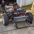
I will add on my praise for this thread. It was a huge time-saver last winter when I started dieting the harness. Now that I'm wrestling that octopus in the car, I still find myself referring back to it when I encounter missing labels or things that seem really out of place.
818C chassis #546. Ordered 8/14/18, picked up 10/6/18. First start 01/16/2021!
Donor: 2006 WRX wagon, 108k miles.
Options: Chassis powder coat, CF street splitter, rockers, diffuser, and spoiler, polished shift knob, adjustable rear lower lateral control arms, vinyl padded dash/door, complete carpet set, battery cut-off switch, wiper kit, aluminum shifter assembly, complete CV axles, harness bar mount, matte gunmetal wheels.
-
12-07-2020, 12:55 PM
#199
Solderseal Splice Connectors
Has anyone used the Solderseal splice connectors? https://solderseal.com/ They look like a great solution but too good to be true?
BTW, this is my first post on this forum, but so far it has helped me tons!
-
12-07-2020, 01:14 PM
#200
Administrator


Originally Posted by
hartwellguy

Has anyone used the Solderseal splice connectors?
https://solderseal.com/ They look like a great solution but too good to be true?
BTW, this is my first post on this forum, but so far it has helped me tons!
I use heat shrink adhesive lined crimp connectors exclusively. Solder joint and anything that vibrates will fail over time
-
Post Thanks / Like - 1 Thanks, 0 Likes


 Thanks:
  Likes:


 Reply With Quote


