Very Cool Parts

Visit our community sponsor

Thanks Thanks:  0
Likes Likes:  0
Page 1 of 2 12 LastLast
Results 1 to 40 of 76

Thread: Engine Build Thread - 427ci FE Big Block

  1. #1
    FFR6671 Fifty-Two's Avatar
    Join Date
    Feb 2011
    Location
    Thousand Oaks, CA
    Posts
    115
    Post Thanks / Like

    Engine Build Thread - 427ci FE Big Block

    _________________________________________________

    **** BUILD UPDATES / TABLE OF CONTENTS ****

    -> 08/07/12 (post #64-67) Oil Pump & Oil Pan: Prep, Pickup Clearance, Final Install
    -> 05/27/12 (post #60-61) Cylinder Heads: Cleaning & Paint Prep, Painting, Blueprinting, Final Install
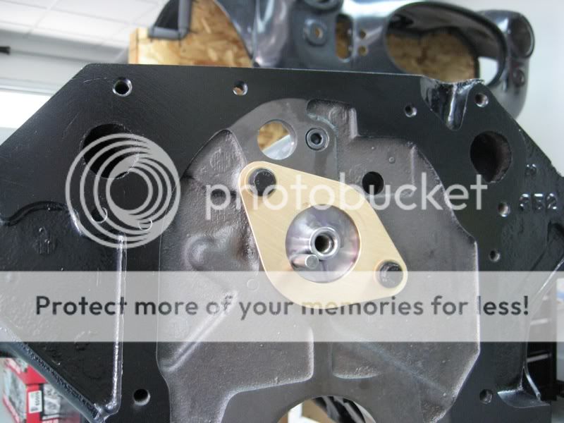
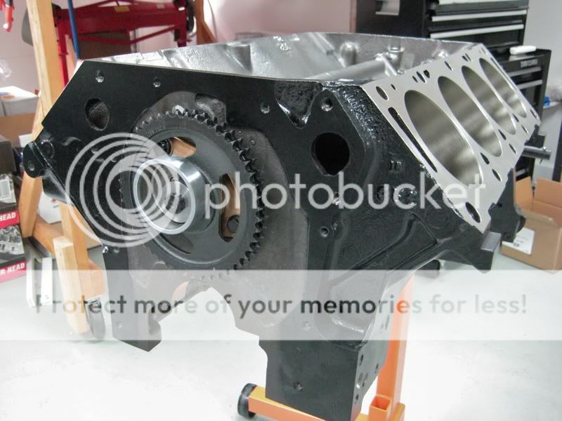
    -> 03/10/12 (Post #54-56) Exterior Components: Front Cover Prep & Install, Balancer Install, Oil Filter Adapter
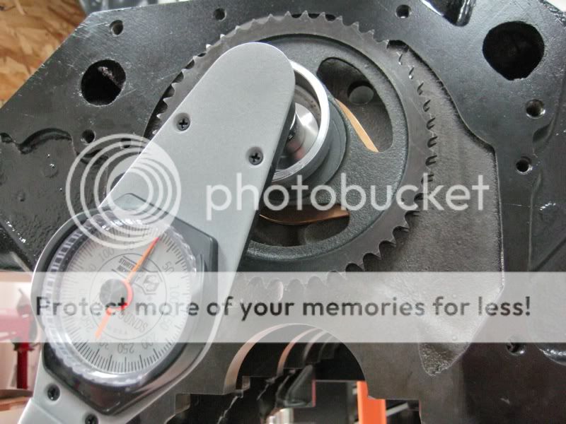
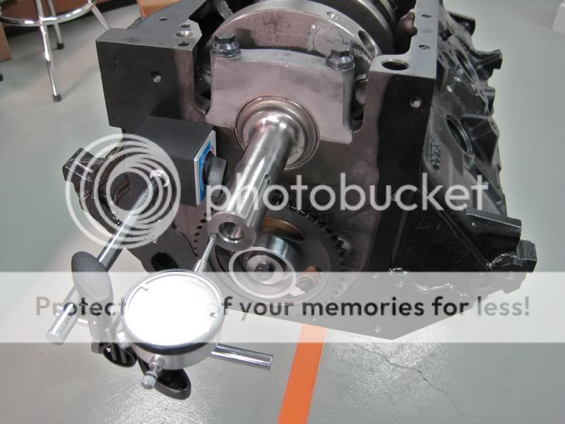
    -> 03/03/12 (Post #53) – Camshaft: Degreeing the Camshaft & Final Timing Set Install
    -> 01/29/12 (Post #51-52) – Rotating Assembly: Final Bottom-End Assembly
    -> 12/20/11 (Post #47) Rotating Assembly: Blueprinting & Balancing
    -> 10/29/11 (Post #46) – Piston Prep & Blueprinting
    -> 08/27/11 (Post #45) – Rods: Rod & Rod Bearing Blueprinting
    -> 07/24/11 (Post #44) – Piston Rings: Filing & Fitting Ring Sets
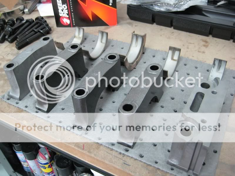
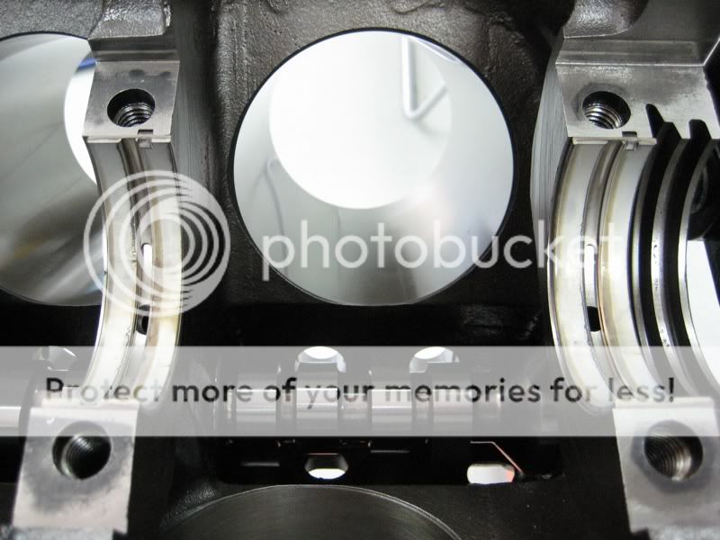
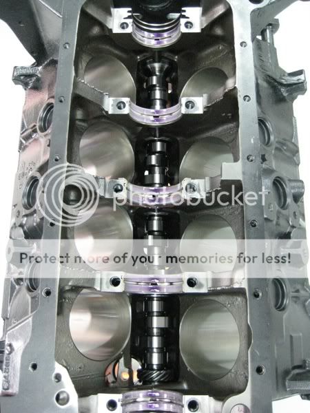
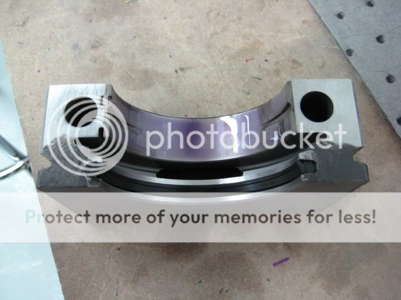
    -> 05/25/11 (Post #37) – Crankshaft: Final Install of Crank & Main Bearings
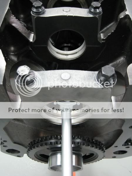
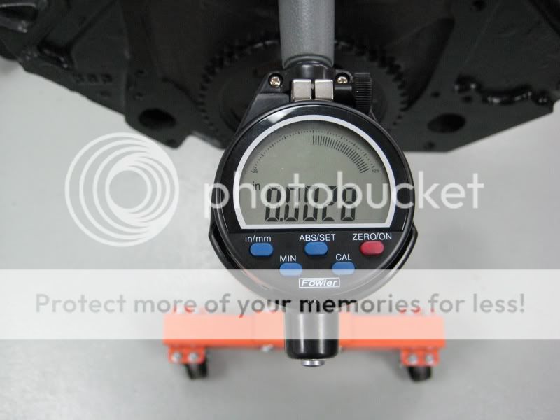
    -> 05/07/11 (Post #28-29) – Crankshaft: Cleaning & Prep, Blueprinting, Main Bearing Clearances
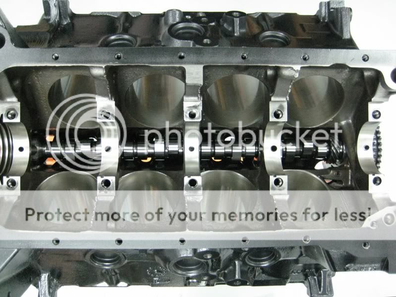
    -> 04/23/11 (Post #24-25) – Camshaft: Additional Components, Cam Install, Measuring Endplay, Final Assembly
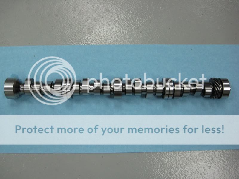
    -> 04/13/11 (Post #16) – Engine Block: Oil Galley Plugs | Camshaft: Selection, Cam Bearings, Blueprinting & Prep
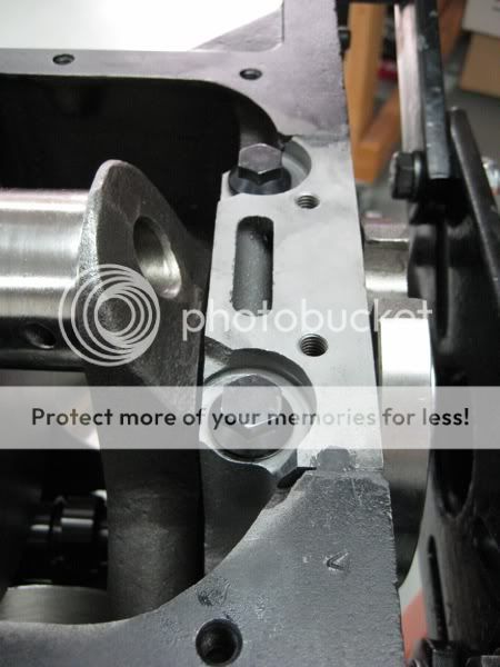
    -> 04/04/11 (Post #14) – Engine Block: Cross Bolts
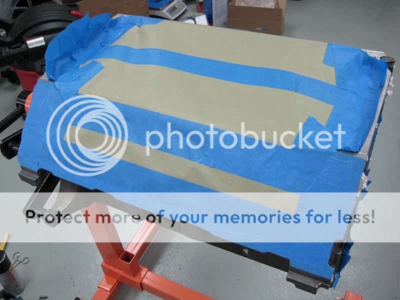
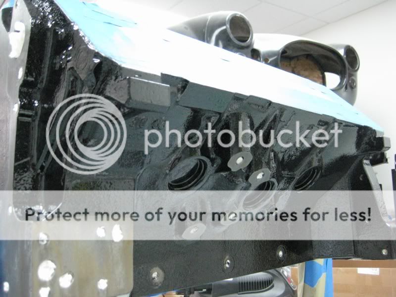
    -> 04/02/11 (Post #9-10) – Engine Block: Casting Flash Removal, Core Plugs, Cleaning & Paint Prep, Painting
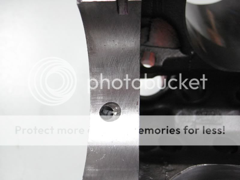
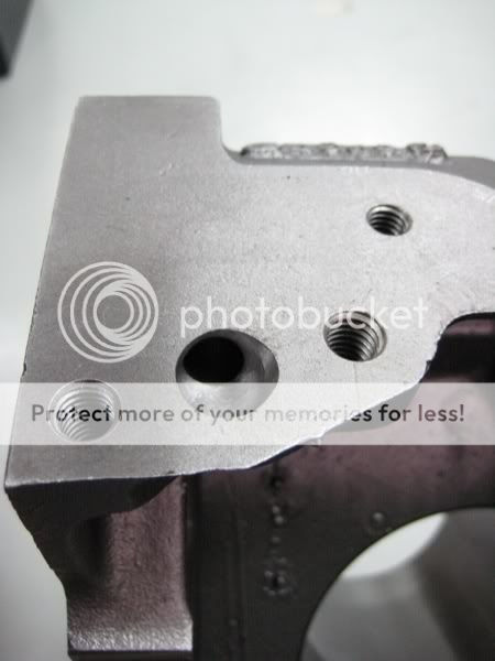
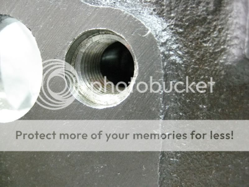
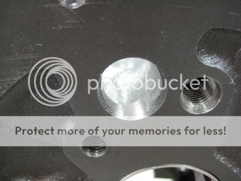
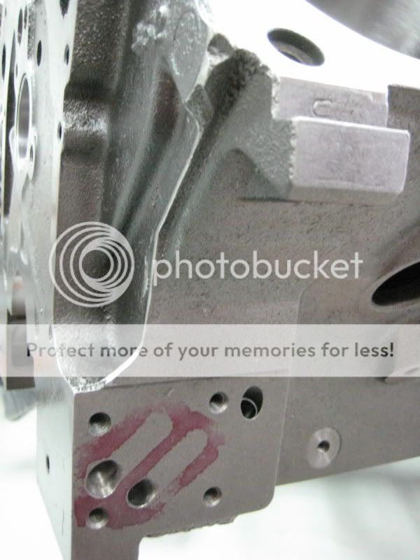
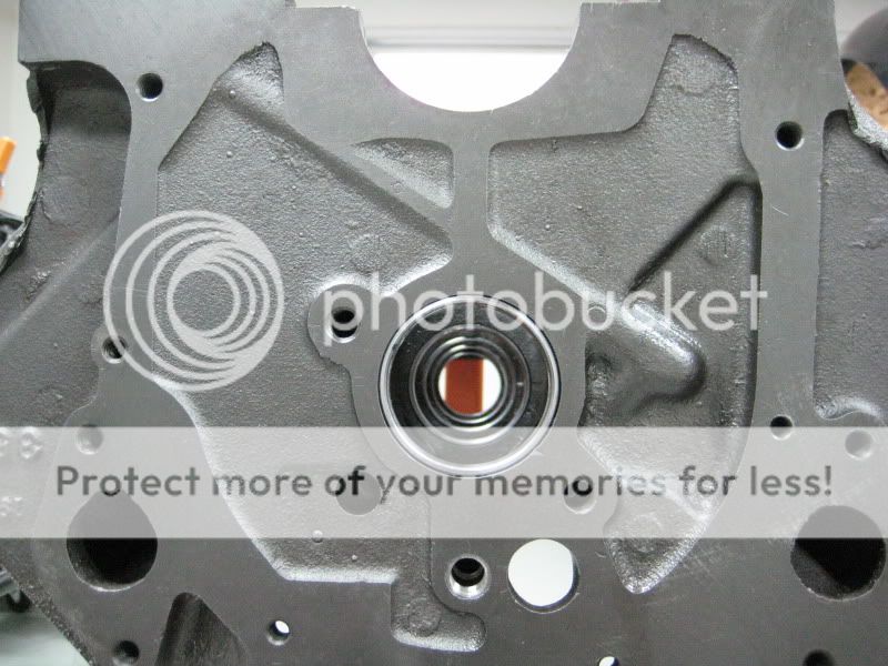
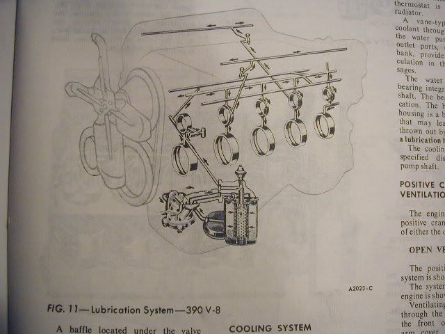
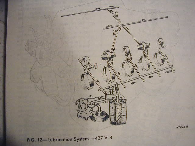
    -> 03/31/11 (Post #4) – Engine Block: Oiling System, Oiling Mods
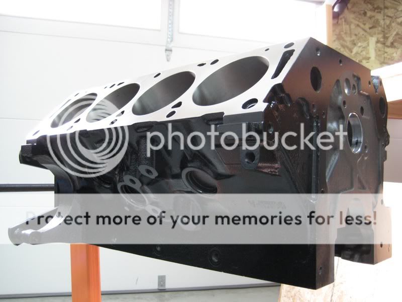
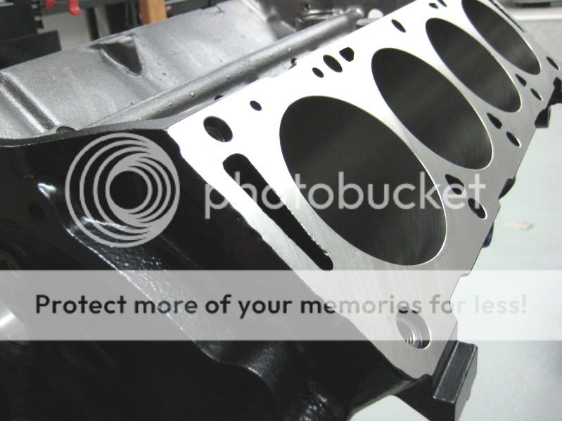
    -> 03/21/11 (Post #2) – Engine Block: Selection, Identification, Machine Work

    _________________________________________________


    Engine Build Thread - 427ci FE Big Block

    Figured I would start a thread to document the buildup of my 427ci FE motor during the next few days/weeks/months. Hopefully I’ll be able to cover most of the steps during the build and have a little fun in the process.

    The concept for this project is simply to build a reliable 427 cubic inch FE big block without having to mortgage the house or take a second job (i.e. this build won’t be based off of a new-casting $3-5k side-oiler block). By boring a readily available seasoned FE 352 or 390 block, and filling it with newer modern componentry, the finished motor should be just as powerful as the original and more street friendly, all the while looking nearly identical on the outside to how the 427’s came out of the factory in ‘65/66.


    Goals
    ~ Displacement of 427 ci (achieved via 4.060” bore & 4.125” stroke)
    ~ Visually Authentic to the ’66 S/C 427 FE Motor
    ~ Reliable & Low Maintenance Street Motor (via Hydraulic Roller Cam & Lifters, etc.)
    ~ Weigh less than an original-spec 427 FE (via Aluminum Heads, Aluminum Intake, etc.)
    ~ 6200 PRM Redline
    ~ 9.5-10:1 Compression Ratio
    ~ Horsepower & Torque = 450+


    Parts & Components
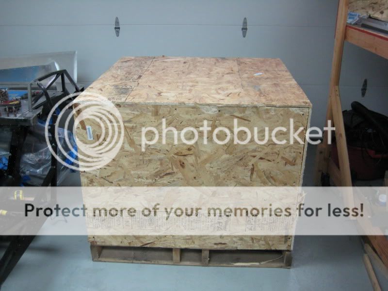
    ~ 1966 Ford 390 FE Block (Bored/Honed to 4.060”)
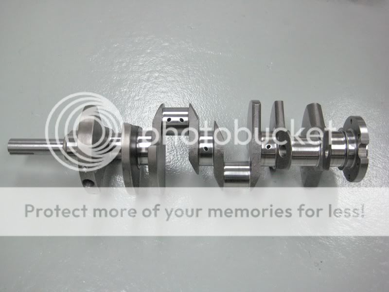
    ~ SCAT 4.125” Stroker Crank (Internally Balanced for custom rotating assembly)
    ~ SCAT Forged I-Beam Rods
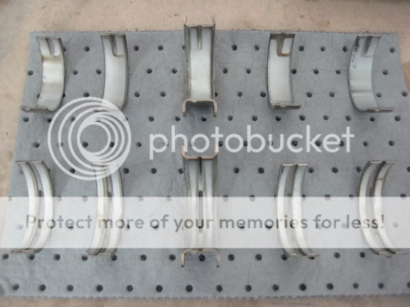
    ~ Speed-Pro Main Bearings & Rod Bearings
    ~ Diamond Forged 4032 Aluminum Pistons (Custom - Dished)
    ~ ARP Bolts: Mains, Rods, Intake, Heads, Cam, Damper, etc.
    ~ Comp Cams Hydraulic Roller Camshaft & Lifters (Survival Motorsports Custom Grind)
    ~ Blue Thunder Bronze Cam Thrust/Retaining Plate
    ~ Edelbrock 60069 Aluminum Cylinder Heads (w/ upgraded Dual Valve Springs to match Cam specs)
    ~ Blue Thunder 427 S/C Reproduction Intake Manifold – Aluminum (#IM-427MR-4)
    ~ Fel-Pro Performance Gaskets: Head (#1020), Intake (#1247-S3), Exhaust (#1442), Misc Completion Kit (#2720)
    ~ PRW 17-4ph SS Roller-tip Rocker Arm Assemblies w/ Billet Aluminum Stands & Hardened Shafts (#3239022)
    ~ ARP Custom Rocker Stand Stud Kit (Precision Oil Pumps)
    ~ Head Oil Restrictors to Rockers (TBD)
    ~ Pushrods – Trend Custom Length (TBD)
    ~ Chrome “Pentroof” Valve Covers
    ~ Blueprinted Melling High Volume Oil Pump (Precision Oil Pumps)
    ~ 1/4" HD Chrome-moly Oil Pump Driveshaft (Precision Oil Pumps)
    ~ 427 Road Race Oil Pan Repro w/ Windage Tray, Pickup, Custom Temp Bung (Armando Racing Oil Pans #408)
    ~ Milodon Crushproof Premium Oil Pan Gaskets (#40450)
    ~ Ford Racing Double Roller Timing Set (#M-6268-A390)
    ~ Cast Aluminum Timing Cover (Reconditioned OE FoMoCo)
    ~ Remote Oil Filter Block Adapter (Trans Dapt #1015)
    ~ Cast Aluminum Remote Oil Filter Housing & Steel Mounting Bracket (reproductions of Originals)
    ~ Crank Oil Slinger (OE Ford N.O.S.)
    ~ Crankshaft Damper Spacer (Billet Steel Repro)
    ~ Professional Products 427-FE Reproduction Damper (7-1/2") & Single-Sheave Pulley (6-5/8")
    ~ Carter Mechanical Fuel Pump - 120 gallons/hour (#GM6905)
    ~ Ford Racing Fuel Pump Eccentric (#M-6287-C302)
    ~ Fuel Filter Canister & Bracket (reproductions of Ford “B7Q-9155-A” & “C0AE-9180-A”)
    ~ 1x4v Fuel Log (reproduction of Original)
    ~ Carb (Holley - TBD)
    ~ “Turkey Pan” Cold Air Plenum
    ~ Stelling & Hellings 8.5" Chrome Air Filter Assembly
    ~ High-Volume Mechanical Water Pump (FlowKooler #1642)
    ~ Ford Water Pump Pulley - Single-Sheave 7-1/4” Diameter (Reconditioned OE FoMoCo)
    ~ Radiator “Surge” Tank (Black, Driver-side Outlet)
    ~ Alternator Bracket Set (Reconditioned OE FoMoCo ‘65-'67)
    ~ 61-amp Autolite Alternator (Repro of “C5TF-10300-F” w/ Red Autolite Stamping)
    ~ 2.62” Alternator Pulley & 13-Blade Alternator Fan (prepped & painted black)
    ~ Distributor & Coil (TBD)
    ~ Plug Wires (TBD)
    ~ Autolite Spark Plugs (#3924)
    ~ Powermaster Mastertorque Mini-Starter (#9606)
    ~ Quicktime Bellhousing & Block Plate (#RM-6056)
    ~ And more to come ...


    - John
    Last edited by Fifty-Two; 08-07-2012 at 08:58 PM.
    Mk 3.1 - FFR6671 - "Trying" to recreate a Semi-Comp 427...
    427ci FE Big-Block / Pin-Drive IRS / TKO600 / Smiths Gauges / SC Dash / 15" Goodyear Billboards
    Fabrication (the fun stuff): 427 Throttle Pedal (SS) : AC Pedals on Wilwood Arms : CSX E-Brake Lever : CSX-Style Footbox Vents (SS) : CSX-Style Dash Support Tubes & Recessed Dash : CSX-Style F-Panels : Firewall Forward 4" : "Full" Rear Drop : Recessed Bulkhead & Exposed Rollbar ... hopefully the list continues!

  2. #2
    FFR6671 Fifty-Two's Avatar
    Join Date
    Feb 2011
    Location
    Thousand Oaks, CA
    Posts
    115
    Post Thanks / Like

    Block Selection, Prep Work, Machine Work

    Block Selection

    With this FE build being based on a readily available and cost effective seasoned 352 or 390 block, I needed to turn to the aftermarket in order to pick up the extra displacement and achieve my goal of having a 427ci big block FE. I had long ago decided I wasn’t going to try and reuse a 40-50 year old factory crank and set of rods with an unknown history ... too much risk in my opinion if I wanted to be able to spin this motor up over 6k and not worry about something letting loose. Plus, the cost to acquire, re-furbish, and upgrade (ARP bolts, etc) those factory pieces is nearly as much as a brand new aftermarket rotating assembly with higher quality pieces. And with the aftermarket, I could take advantage of available stroker cranks and custom piston diameters to get to my 427ci goal. A low mileage or service 390 block can be power-honed to a 4.060” bore diameter (a 352 block can also be used and easily bored/honed out to that same diameter). This is a very small over-bore, leaving ample thickness in the cylinder walls for proper strength and cooling (and can even be over-bored again in a future rebuild if desired). The 4.060” bore spec combined with a 4.125” aftermarket stroker crank creates the target displacement of 427 cubic inches.

    Additionally, I wanted to source a ’65+ block to take advantage of all the minor upgrades to the FE line that occurred during the early 60’s (additional motor-mount holes, alternator mounting hole, wider #3 main thrust bearing, deeper head & main bearing bolt holes, etc).

    The last requirement on the list was that the block needed to have provisions to run the hydraulic roller lifters being used in this build (meaning the block must have the two factory drilled longitudinal oil galleys necessary to feed hydraulic lifters).

    With all of that decided on, and since I only needed a seasoned block for this project (not an entire donor or pullout motor), I had Barry at Survival Motorsports source the block and spec the machine work for me.


    Prep & Machine Work

    The block prep consisted of a bake cycle, then a media blast, followed by a hot-tank wash; it’s amazing how the block looks nearly brand new when it’s all done.

    Block machine work consisted of the following:
    ~ Bore & Hone all cylinders to 4.060” (w/ torque plates installed to replicate distortion from cylinder heads & hardware)
    ~ Line Hone the main bearing bores (to create round and in-line bores for all the crank journals)
    ~ Mill & Parallel both deck surfaces


    And here's how the machined block showed up at my door:


    Now free from its container:


    And finally, up and mounted on the engine stand:


    Casting Codes / Block Identification

    Now for the decoding ...

    On this block, underneath the oil filter pad is a “6D27” casting date code; the “6” represents 1966, the “D” represents the fourth month of the year (April), and the “27” represents the day of the month in which the block was cast; meaning, this block was cast on April 27th, 1966.


    The other code of interest is the “C6ME-A” casting number located on the passenger side of the block. In this instance though, the number doesn’t provide much info. Theoretically, with this code the block could be a 352, 390, 410, or 428 FE block ... or even a 330 or 391 FT truck block). Ford definitely didn't make it easy to identify these engines.


    In the end, this particular block is indeed a 390 and was verified by the “drill bit test”. This simple check of the spacing between cylinder walls in the water jacket is considered the most reliable way to find the true identity of any particular FE block.


    There are plenty of good write-ups already out there on how to perform this test, so I won’t go into detail here. In short, this block was confirmed as a 390 because a 15/64” drill bit shank was the largest I could fit between two cylinder walls in the water jacket. And that 15/64” spec makes it a relatively thick-walled 390 too, which is great news for overall cylinder wall strength in this motor.


    Additional photos of the block here: http://s628.photobucket.com/albums/u...ngine%20Block/


    Next installment ... Oiling System Mods.


    - John
    Last edited by Fifty-Two; 03-31-2011 at 10:20 AM.
    Mk 3.1 - FFR6671 - "Trying" to recreate a Semi-Comp 427...
    427ci FE Big-Block / Pin-Drive IRS / TKO600 / Smiths Gauges / SC Dash / 15" Goodyear Billboards
    Fabrication (the fun stuff): 427 Throttle Pedal (SS) : AC Pedals on Wilwood Arms : CSX E-Brake Lever : CSX-Style Footbox Vents (SS) : CSX-Style Dash Support Tubes & Recessed Dash : CSX-Style F-Panels : Firewall Forward 4" : "Full" Rear Drop : Recessed Bulkhead & Exposed Rollbar ... hopefully the list continues!

  3. #3
    Junior Member
    Join Date
    Feb 2011
    Location
    Elephant Butte, NM
    Posts
    19
    Post Thanks / Like
    Great report. Keep it up as I thoroughly enjoy reading about building up the old FE's. I originally wanted to go with a 390 in my car but after much consideration opted for the injected 347. Still think about it though.

  4. #4
    FFR6671 Fifty-Two's Avatar
    Join Date
    Feb 2011
    Location
    Thousand Oaks, CA
    Posts
    115
    Post Thanks / Like

    Oiling System / Oiling Mods

    Side-Oiler vs Top-Oiler

    Figured I’d toss in a quick history of the two different styles of oiling systems in the FE family: side-oiler & top-oiler. The difference lies simply in the sequence that each of the engine components receives its lubrication.

    The “top-oiler” design was used on the vast majority of FE blocks produced by Ford (352, 360, 390, 410, etc) - even the 428 motor that powers most of the “427” Street Cobras was a top-oiler block. With this lubrication strategy, oil is primarily fed via a longitudinal center oil galley (located just below the lifter valley) and is dispersed from the top of the block to the bottom, meaning the lifters and cam bearings are the first to receive oil, as lubrication then makes its way down to the main bearings.

    The “side-oiler” design on the other hand, was born out of racing necessity where the oiling priority needed to be to the main bearings first and foremost; this design has a main oil galley running lower along the side of the block to feed the mains, then galleys going upwards to feed the cam, etc. Many of the 427 motors were of this design (there were 427 top-oilers produced though). This side-oiler design was advantageous in theory because with any oil-pressure fluctuation or drop, the mains were still the first to receive oil and hopefully wouldn’t be starved (i.e. spun bearing). In practical application for a well built and blue-printed street motor, the difference is minimal to none; and with a few small oil-system modifications made to a top-oiler block (plus the addition of a high-volume oil pump), the main bearings stay very well lubricated and are completely protected. In an all-out racing application (such as 7-8k RPM, 650+ hp drag/road-racing), the side-oiler definitely has its merits, but for my purpose in a mostly street-driven Cobra, provides no quantifiable advantage. Also, most original side-oiler blocks were for use with solid lifters only and cannot be converted; in order to run a hydraulic roller cam, I would have most likely had to spring for a new-casting block (Genesis, Pond, etc) that has the necessary oil galleys drilled out for use with the hydraulic lifters. Unfortunately, the extra $3-5k for that block isn’t budgeted in my build; and truthfully, just flat out isn’t necessary for this project.


    Oiling Mods & Upgrades

    As mentioned earlier, by performing a couple small modifications to the block, the oiling system is vastly improved and becomes nearly bulletproof. And again, there are a plethora of great articles and books already out there on how to perform these mods so I won’t go into a lot of detail in this post.

    Here’s the list of mods done on the block for this particular build:

    ~ Main Saddles: On FE blocks, there is a small misalignment between the oil supply holes (in main saddles # 1, 2, 4) and the oil supply openings in the main bearings themselves. To correct this, the entry portion of the holes on these three saddles were enlarged with a die grinder and blended to match the corresponding openings in the bearings.


    ~ Oil Pump Mount: There is a single opening in the block here, and is where the pump feeds oil up/over to the block’s oil filter mounting pad. This hole was enlarged with a die grinder (gasket matched to the new Melling oil pump), and the bowl/transition feeding into the passageway was opened & blended to aid oil flow.


    ~ Oil Filter Mounting Pad: There are two openings in this area; the first is the one exiting from the block (containing oil from the passageway connected to the pump) and heading out to the remote oil filter; the second one is the opening coming back from the remote oil filter that feeds back into the block to lubricate the engine. Both of these holes were enlarged and blended with a die grinder to aid in oil flow to/from the block; machinist’s dye was used to create an outline of the gasket (for the remote oil filter adapter) on the block, serving as a template to insure the holes weren’t enlarged too far.


    ~ Oil Galley Plugs: Depending on the particular year/type of block, some of the galley plug openings were tapped (1/4" NPT) by the factory, while others were left as a standard “press-fit” type plug. For a little extra security against one of the plugs popping out and the engine losing oil pressure, all of the remaining press-fit openings were tapped to accept the same 1/4" NPT plugs. A quick note: the one plug behind the distributor isn’t at risk to go anywhere and is fine to leave in stock form; so, it remained as a press-fit plug in this block.


    ~ Oil Drainback Holes: The drainage holes at the front & rear of the lifter valley were opened/deburred with a die grinder to help aid in oil flow back down to the pan.


    ~ Blueprinted High-Volume Oil Pump: To help move more lubrication through the oil galleys and provide a boost in oil pressure at idle and low RPM’s, a high-volume Melling oil pump (M57HV) was chosen. And to insure that the pump was set up to spec and working as efficiently as possible, it was blueprinted by Doug at Precision Oil Pumps - he does an awesome job with these and the work is top notch. I also decided to run one of his upgraded chrome-moly 1/4" oil pump drive shafts for a little extra peace of mind against the possibility of an oil pump drive shaft failure (thus starving the engine of oil and ruining my day/week/month/year).


    Additional photos of the block here: http://s628.photobucket.com/albums/u...ngine%20Block/

    Next installment ... Finishing up the block.

    - John
    Last edited by Fifty-Two; 03-31-2011 at 07:33 PM.
    Mk 3.1 - FFR6671 - "Trying" to recreate a Semi-Comp 427...
    427ci FE Big-Block / Pin-Drive IRS / TKO600 / Smiths Gauges / SC Dash / 15" Goodyear Billboards
    Fabrication (the fun stuff): 427 Throttle Pedal (SS) : AC Pedals on Wilwood Arms : CSX E-Brake Lever : CSX-Style Footbox Vents (SS) : CSX-Style Dash Support Tubes & Recessed Dash : CSX-Style F-Panels : Firewall Forward 4" : "Full" Rear Drop : Recessed Bulkhead & Exposed Rollbar ... hopefully the list continues!

  5. #5
    Senior Member PhyrraM's Avatar
    Join Date
    Feb 2011
    Posts
    1,468
    Post Thanks / Like
    While I'm usually not really a fan of the older motors (anymore), this one is gonna be SWEET! Looking forward to the rest of the build up.

    I like the attention to detail you've already put into it.

  6. #6
    Senior Member Lex's Avatar
    Join Date
    Feb 2011
    Location
    Nashville, Tn
    Posts
    101
    Post Thanks / Like
    This thread couldn't have come at a better time. Guess what my new project is I started a couple weeks ago?
    FFR 4298 Mk III, 5.0, Dual Quads, 3.73 Gears, B303 cam, Pin Drive Vintage Wheels and way too much to list here!
    "It's loud, smells like gasoline, and shakes, shudders, and bucks. It makes your arms tired and your feet hot. You nearly crash about once every ten minutes. It's so damn wonderful you can’t believe it."

  7. #7
    FFR6671 Fifty-Two's Avatar
    Join Date
    Feb 2011
    Location
    Thousand Oaks, CA
    Posts
    115
    Post Thanks / Like
    I had a feeling you'd come to the dark side eventually! Good stuff!!!
    Mk 3.1 - FFR6671 - "Trying" to recreate a Semi-Comp 427...
    427ci FE Big-Block / Pin-Drive IRS / TKO600 / Smiths Gauges / SC Dash / 15" Goodyear Billboards
    Fabrication (the fun stuff): 427 Throttle Pedal (SS) : AC Pedals on Wilwood Arms : CSX E-Brake Lever : CSX-Style Footbox Vents (SS) : CSX-Style Dash Support Tubes & Recessed Dash : CSX-Style F-Panels : Firewall Forward 4" : "Full" Rear Drop : Recessed Bulkhead & Exposed Rollbar ... hopefully the list continues!

  8. #8
    Senior Member Lex's Avatar
    Join Date
    Feb 2011
    Location
    Nashville, Tn
    Posts
    101
    Post Thanks / Like
    Quote Originally Posted by Fifty-Two View Post
    I had a feeling you'd come to the dark side eventually! Good stuff!!!
    Who me? LOL! Something I've been wanting to do for quiet a while.
    FFR 4298 Mk III, 5.0, Dual Quads, 3.73 Gears, B303 cam, Pin Drive Vintage Wheels and way too much to list here!
    "It's loud, smells like gasoline, and shakes, shudders, and bucks. It makes your arms tired and your feet hot. You nearly crash about once every ten minutes. It's so damn wonderful you can’t believe it."

  9. #9
    FFR6671 Fifty-Two's Avatar
    Join Date
    Feb 2011
    Location
    Thousand Oaks, CA
    Posts
    115
    Post Thanks / Like

    Finishing Up The Block

    Exterior Casting Cleanup

    Just for cosmetic purposes, I decided to clean up some of the casting flash on the exterior of the block. Ford never bothered to clean up this type of cosmetic stuff back in the day, but a few minutes spent with my angle & die grinders took care of all of it. The usual areas where this casting flash is an eyesore is at the edges of the front corners on either side of the block (see photos below). There is also a fair amount of flash on the corner edges at the back of the block and around the starter pocket area too; its less visible back there, but I still decided to get rid of it since I already had the tools out to do it.

    Before (passenger-side front):


    After (passenger-side front):


    Before (driver-side front):


    After (driver-side front):


    Deck Cleanup

    Another area that needed attention was the block's deck surfaces. After the decking machine work was completed, the machinist went ahead and lightly chamfered the cylinder bore edges to help make sure that piston rings wouldn’t get hung up during install later down the road.

    It’s also recommended to chamfer the head-bolt holes on each deck (since the head-bolts tend to slightly pull up the surrounding deck surface when tightened), as well as chamfer the 4 head dowel-pin holes (to make the dowels easier to insert). I used a few mini files and a knife sharpening stone to accomplish this; it is important to note that the direction of filing should always move from the deck surface, downward into the hole; filing in this directions helps to make sure that no burrs are created above the deck surface (any burrs could prevent the head gaskets from sealing properly).


    Thread Chasing & Cleaning

    Even after all the hot-tanking, baking, and media blasting the block went through at the machinist's, many of the bolt-holes still had years of gunk worked into the threads. To achieve proper clamping loads and torque values during the assembly process later down the road, it’s important that these holes and threads be completely clean. For this project, I sourced an affordable set of NC (course) thread chasing taps from Jegs that covers every bolt-hole size on the block (http://www.jegs.com/i/JEGS+Performan...80505/10002/-1). Normal hardware store taps are not designed to “chase” and clean out old threads; they are designed to cut and create new threads. So, using normal taps to clean out these holes could remove not only the gunk, but also some of the metal from the threads themselves … not a good thing. The chasing tap set was money well spent because it made the tedious task of cleaning out the 80+ threaded holes in this block a bearable ordeal. The process I used consisted of:
    ~ A shot of brake cleaner down each bolt-hole
    ~ Followed by running the tap down and back a couple times
    ~ Then another shot of brake cleaner
    ~ Next came compressed air to get everything out of the hole
    ~ And finally, a shot of WD40 went into each hole to prevent any corrosion


    Final Block Cleaning

    After all the grinding, filing, and other block prep was finished, it was time to wash down the block to get rid of any remaining grit, grease, dirt, machining oils, etc. This brush kit from Moroso worked out perfectly - http://www.summitracing.com/parts/MOR-61820 - There are multiple sizes and lengths of galley brushes that took care of all the different oil passages, as well as brushes sized for the lifter bores and cylinder bores to really get those areas squeaky clean. I started out with a full scrub down using Simple Green, followed by a second scrub down with hot water and detergent. I focused heavily on making sure that all the oil passageways were scrubbed out with the galley brushes and that no trace of contaminants remained anywhere on or inside the block. Just as a side note … its easy to overlook the two oil galleys that run from the #2 and #4 cam bores, back up to a small opening in each of the cylinder decks (these feed lubrication up to heads for the rocker system); luckily, I remembered them at the last moment before I had wrapped up with the cleaning.

    For the lifter bores and cylinder bores, I mounted their respectively sized brushes in an electric hand drill and went to town using plenty of hot soapy water as a cleaning aid and lubricant. As everyone already knows, it cannot be emphasized enough as to how clean the block needs to be - especially the cylinder bores themselves. There is a lot of debris from the machining & honing process that gets embedded into those walls and it takes a ton of scrubbing to really dig it out from all of the little cross-hatches, etc … nothing kills rings faster than cylinder bores that aren’t 100% clean.

    Once all the cleaning and scrubbing was done, I thoroughly rinsed out every single inch of the block. A high-pressure nozzle was used to force water through each of the oil galley openings (4 on top, 4 in back, 3 in front, 2 on side) and through every single oiling orifice (main bores, cam bores, decks, etc). With the rinse done, the next battle was with time … surface rust can start forming immediately on a completely clean block, so a blow dry with compressed air came next (machined surfaces first, bolt holes and passageways next, then the rest of the block). WD40 was liberally applied on all the cylinder walls and other machined surfaces, inside all the oil galleys and openings, in the lifter valley/bores, and any other areas that weren't receiving paint. It was a job that I came away from soaking wet and cold, but nonetheless was very confident that everything was as clean as it could be.


    Installation of Core Plugs & Coolant Drain Plugs

    This block (as do most FE blocks) uses 6 press-fit core plugs to seal off the water jackets; the plug kit I’m using has a set of upgraded brass core plugs that are much more corrosion resistant than standard steel plugs. Each side of the block has 3 of these plugs, and all were driven in with a dead-blow hammer and socket (I found that my 1-1/8" impact socket was the perfect size to fit inside the plug and use as the drive tool); a thin layer of JB Weld was applied to each plug as a sealant and extra insurance against one of them coming back out.


    The 1/4" NPT coolant drain plugs (1 on each side of the block) were re-installed using teflon paste thread-sealant to prevent any possible water leaks.

    Mk 3.1 - FFR6671 - "Trying" to recreate a Semi-Comp 427...
    427ci FE Big-Block / Pin-Drive IRS / TKO600 / Smiths Gauges / SC Dash / 15" Goodyear Billboards
    Fabrication (the fun stuff): 427 Throttle Pedal (SS) : AC Pedals on Wilwood Arms : CSX E-Brake Lever : CSX-Style Footbox Vents (SS) : CSX-Style Dash Support Tubes & Recessed Dash : CSX-Style F-Panels : Firewall Forward 4" : "Full" Rear Drop : Recessed Bulkhead & Exposed Rollbar ... hopefully the list continues!

  10. #10
    FFR6671 Fifty-Two's Avatar
    Join Date
    Feb 2011
    Location
    Thousand Oaks, CA
    Posts
    115
    Post Thanks / Like

    Finishing Up The Block (continued)

    Paint Prep

    ~ Solvent Cleaning: To eliminate any residual WD40 or other oils on the exterior of the block, I used a couple cans of brake cleaner to completely clean and decontaminate the surface for the next step.

    ~ Etching Solution: POR15 will be used as the basecoat on this block, so the recommended next step in the surface prep is their “Prep & Clean” solution - this stuff neutralizes any remaining surface rust, creates a light etch in the metal, and leaves a zinc phosphate coating behind ... all of which evidently help the POR15 adhere to the block like mad. When using this solution, make sure to keep if off of any surface that won’t be getting painted (especially the machined surfaces like the decks), because you don’t want those places to get any type of etching at all. I used a small spray bottle and carefully applied it only to the areas of the block that were going to receive paint. It is a very slow acting etch, so if any of the solution does happen to hit a machined surface, if wiped off quickly, it won’t do anything to the metal. After the solution sat of the block for about 15 min, it was then rinsed off with fresh water and the block was blown dry with compressed air.

    This is what the metal finish looks like after the etching solution step is complete:


    ~ Solvent Cleaning (again): As a final step, just to make double and triple sure that the surface is 100% ready to receive paint, I took a lint free cloth along with a can of acetone and wiped down every single surface that was to be painted.

    ~ Masking: A tedious and time-consuming process, but the effort put in here will pay dividends on the final product. Everything that wasn’t getting paint was completely covered and taped up (decks, lifter valley, bottom end internals, galley plug areas, cam plate area, etc). I used a fresh razorblade to trim the tape edges around all the deck surfaces and other critical areas. Additionally, all of the exterior bolt-holes and exposed galleys were plugged to keep paint out.


    Block Painting

    For this project, I decided to use POR15 (semi-gloss black) as the basecoat on the block. This stuff is not only unbelievably strong and chip-resistant, but also does an amazing job of sealing and bonding to the metal to prevent ANY rust issues in the future. It also is resistant to high temps (up to 600 F), so is perfect for engine block applications. I applied two thin coats a couple hours apart using simply a paintbrush - this stuff is self-leveling and absolutely no brush marks show up, especially on a rough texture cast iron surface like this. The one downside to POR15 though, is that it isn’t very UV stable and the color can fade over time. Because of this, it is recommended to apply a topcoat over the POR15. And, if you apply the topcoat before the POR15 basecoats cure, there is no need for a primer or tie-coat in between. For the topcoat in this application, I’m using a semi-gloss back ceramic engine enamel from Duplicolor. Per instructions, I sprayed on two light coats, followed by a final medium coat ... allowing about 10 min flash time between each of the 3 coats. And the beauty of having the POR15 underneath, is that if the ceramic enamel topcoat ever does happen to take a hit and chip, the POR15 layer underneath (in semi-gloss black to match the topcoat) isn’t going anywhere.

    After the 2 basecoats of POR15:


    After the 3 topcoats of Ceramic Enamel:


    After everything was unmasked, here is what the final product looked like:


    Additional photos of the block here: http://s628.photobucket.com/albums/u...ngine%20Block/


    Next installment ... Camshaft selection & prep.

    - John
    Last edited by Fifty-Two; 04-13-2011 at 08:17 PM.
    Mk 3.1 - FFR6671 - "Trying" to recreate a Semi-Comp 427...
    427ci FE Big-Block / Pin-Drive IRS / TKO600 / Smiths Gauges / SC Dash / 15" Goodyear Billboards
    Fabrication (the fun stuff): 427 Throttle Pedal (SS) : AC Pedals on Wilwood Arms : CSX E-Brake Lever : CSX-Style Footbox Vents (SS) : CSX-Style Dash Support Tubes & Recessed Dash : CSX-Style F-Panels : Firewall Forward 4" : "Full" Rear Drop : Recessed Bulkhead & Exposed Rollbar ... hopefully the list continues!

  11. #11
    Junior Member
    Join Date
    Mar 2011
    Posts
    29
    Post Thanks / Like
    Have you thought about painting the internal engine w/ http://www.eastwood.com/glyptal-red-brush-on-1-qt.html

    quote from one of the reviews "It allows the rough interior casting surfaces to smooth out and allows lubrication to return to it's sump without "clogging" or building up as can be seen when re-building components.:

  12. #12
    Junior Member
    Join Date
    Mar 2011
    Posts
    7
    Post Thanks / Like
    Question. Are you doing simulated crossbolts? I see 2 bolt mains and holes for crossbolts. The block looks great. Very nicely detailed and good pics too.

  13. #13
    FFR6671 Fifty-Two's Avatar
    Join Date
    Feb 2011
    Location
    Thousand Oaks, CA
    Posts
    115
    Post Thanks / Like
    Quote Originally Posted by cozmacozmy View Post
    Have you thought about painting the internal engine w/ http://www.eastwood.com/glyptal-red-brush-on-1-qt.html
    Its definitely something I considered because the concept makes complete sense and it looks to be a simple solution. Ultimately though, its something I decided against. There are a whole lot of opinions out there on Glyptal ... some great, some ugly. I've never had a chance to use it myself, so everything I based my decision on was second-hand info. The inherent risk that seemed to come up most often when I was researching it, is that if the Glyptal starts to flake or peel off of the block internals, those pieces of paint can start clogging up oil pickups, oil pumps, oil passageways, etc ... all of which are very bad things. There are definitely some potential benefits to using it as you mentioned, and there are many engine builders who swear by the stuff, but in the end I felt that the modest possible upside didn't outweigh the potential risk. And this seems to be the current opinion by many of the big FE shops nowadays as well (Barry Robotnik's book goes into a good discussion about this, and was one of the main reasons I decided against it actually). Hope that all made sense.

    - John
    Mk 3.1 - FFR6671 - "Trying" to recreate a Semi-Comp 427...
    427ci FE Big-Block / Pin-Drive IRS / TKO600 / Smiths Gauges / SC Dash / 15" Goodyear Billboards
    Fabrication (the fun stuff): 427 Throttle Pedal (SS) : AC Pedals on Wilwood Arms : CSX E-Brake Lever : CSX-Style Footbox Vents (SS) : CSX-Style Dash Support Tubes & Recessed Dash : CSX-Style F-Panels : Firewall Forward 4" : "Full" Rear Drop : Recessed Bulkhead & Exposed Rollbar ... hopefully the list continues!

  14. #14
    FFR6671 Fifty-Two's Avatar
    Join Date
    Feb 2011
    Location
    Thousand Oaks, CA
    Posts
    115
    Post Thanks / Like

    Cross-Bolts

    Quote Originally Posted by FFR428 View Post
    Question. Are you doing simulated crossbolts? I see 2 bolt mains and holes for crossbolts. The block looks great. Very nicely detailed and good pics too.
    Yup, you are spot on! I was wondering how long it would take someone to notice that.

    The only FE blocks that came with the cross-bolted mains were the 427's and some of the late 406's. All of the other FE blocks (332, 352, 360, 361, 390, 410, & 428) didn't have these cross-bolts, nor did they even have the millwork and holes drilled in the skirts to use them.

    Many FE blocks can be converted to use functional cross-bolted main caps, but finding a set of those Ford caps is nearly impossible or way too expensive. And while they do have their merits for high-performance race applications and big horsepower motors, they truly won't make much (if any) of a difference on a 400-500 hp street-oriented motor like I am building here ... mostly due to the fact that all FE blocks were blessed with that wonderfully strong deep-skirt design, and the regular (non cross-bolt) main caps are able to do a perfectly fine job of keeping flex and distortion at bay in applications like mine.

    I did however want the look of those bad-a** 427 cross-bolted blocks.
    So while the block was already at the machinist's for all the other standard work being done, I had them go ahead and mill the 6 spotfaces into the block's skirt area (3 on each side - inline with the #2, #3, #4 main caps) to match the exact places from a 427 block; these spotfaced circles allow the washers to lay flush against the skirt surface, just as it was on the originals. Then, the 6 corresponding holes were drilled and tapped for the mock 3/8" cross-bolts.


    Here are a couple photos of the finished product:


    And for hardware, I'll be using factory Ford "place bolts" and washers to complete the look. AMK seems to be the best place I've found to source OE-style Ford hardware: http://www.amkproducts.com/bulk2.asp...le=Place+Bolts


    - John
    Last edited by Fifty-Two; 04-08-2011 at 08:04 PM.
    Mk 3.1 - FFR6671 - "Trying" to recreate a Semi-Comp 427...
    427ci FE Big-Block / Pin-Drive IRS / TKO600 / Smiths Gauges / SC Dash / 15" Goodyear Billboards
    Fabrication (the fun stuff): 427 Throttle Pedal (SS) : AC Pedals on Wilwood Arms : CSX E-Brake Lever : CSX-Style Footbox Vents (SS) : CSX-Style Dash Support Tubes & Recessed Dash : CSX-Style F-Panels : Firewall Forward 4" : "Full" Rear Drop : Recessed Bulkhead & Exposed Rollbar ... hopefully the list continues!

  15. #15
    Junior Member
    Join Date
    Mar 2011
    Posts
    7
    Post Thanks / Like
    Yup castle head bolts will complete the look. The original crossbolts was the same hardware as the long intake manifold bolts. The thick washers are the same ones used on the rocker stand bolts. Nice touch.

  16. #16
    FFR6671 Fifty-Two's Avatar
    Join Date
    Feb 2011
    Location
    Thousand Oaks, CA
    Posts
    115
    Post Thanks / Like

    Camshaft

    Oil Galley Plugs

    One quick loose end that I needed to finish up before moving onto the cam was to plug and seal all the oil galleys in the block. Most of the FE plug kits only contain a few of the threaded 1/4” NPT galley plugs - the rest are usually standard 1/4" press-fit plugs. And since all the galley openings on this block were tapped to utilize the NPT plugs (except the one behind the distributor), I needed to source additional 1/4" NPT plugs. These flush-mount NPT plugs from McMaster (part #4534K42) work well because they are a little shorter than standard plugs and are especially ideal for the four galley openings in the rear of the block. The shorter length insures the plugs won’t sit above the engine-plate mounting surface, which could have caused interference issues depending on the particular engine plate used and whether it had been clearance in these spots.

    For this particular block, here’s the list of oil galley plugs:
    ~ Front of Block = 1 (flush-mount NPT)
    ~ Front of Block, behind Distributor = 1 (Press-fit with a drilled 0.030” hole for distributor gear lubrication)
    ~ Lifter Valley = 4 (standard NPT)
    ~ Rear of Block = 4 (flush-mount NPT)
    *Note: The two bolts that attach the cam retaining plate to the front of the block also act to seal off oil galleys.

    Depending on the year and casting type, some FE blocks will have more galley plugs (i.e. side-oiler hydraulic blocks), some will have fewer (i.e. solid lifter blocks). As a side note, for industrial (and some other) blocks, there most likely is an extra galley opening in the oil filter pad area (which was probably used for compressor or accessory oiling) that will need to be plugged – good info about that here: http://www.erareplicas.com/427man/engine/oilpress.htm


    Photo of several installed lifter valley plugs:


    Photo of the 0.030” hole drilled into the press-fit plug (behind the distributor):


    Cam Bearings

    Since I don’t own a cam bearing install tool, I had earlier made the easy and cost effective decision to go ahead and have Survival install the new set of Clevite cam bearings into the block before it shipped out to me. FE cam bearings are traditionally a little finicky anyway, so by having the pros do it I know the install was done right and I shouldn’t have any issues with bearing/camshaft clearances from cocked placement.


    Here’s a photo of the install as received from Survival:


    Camshaft Selection & Specs

    First off, let me state that I am by no means a camshaft expert and the million different nuances involved with valve timing events and how they intermix and play off one and other; my knowledge is nowhere near that deep. The choices laid out below are just the over-arching themes as to the direction I went with for this particular build. Once I had made those decisions, I left it to the experts to find the best fit and spec the cam grind itself.

    One of the original goals for this project was to have a reliable and low-maintenance street motor. So when it came time for camshaft selection, the decision to use a hydraulic roller was simple. With too many instances of engines wiping out flat tappet cams in recent years (whether its from newer low-zinc oils, improper break-in, poor quality cores, plain old bad luck, etc.), a modern roller cam eliminates that possibility altogether … as well as the associated break-in procedure and finger crossing. This helps fulfill the “reliable” portion of the criteria; the hydraulic aspect of this cam helps fulfill on the “low-maintenance” portion. By going hydraulic, I won't have to mess with the initial hot/cold valve lash setups and the perpetual chore of re-lashing valves as the miles roll on. All that’s necessary with the hydraulic setup is setting the initial lifter preload, and that’s all she wrote.

    Besides the reliability/maintenance advantages of the hydraulic roller cam, the performance advantages are just as impressive. Since roller-tappets reduce the traditional valve-train friction that occurs between the cam lobes and lifters, an immediate power gain is realized (10-15+ hp) just from that aspect alone. More importantly though, the lower friction creates a potential for higher tappet velocity (plus allows for higher spring pressures & bigger lift potentials). And this capacity for higher tappet velocity permits a camshaft grind with steeper lobe profiles to be utilized. The end result is valves that move with higher velocity as well – they will open fully quicker, and remain fully open longer (because they are able to close faster now as well) … all without an increase in the cam’s actual intake/exhaust duration. This is a key reason why a modern hydraulic roller cam grind can outperform a tradition flat-tappet cam of the same advertised duration. Conversely, this can be used to improve street manners as well – by using a slightly shorter duration roller cam grind (the decrease in overlap will net improved throttle response, idle quality, vacuum, etc.), the same overall power can be made as the slightly longer duration flat-tappet cam.

    The main downsides to a hydraulic roller cam are: the overall cost, and the RPM limits that are innate to the hydraulic lifters themselves. Since this will be a street-oriented motor though, and I’ve decided to spec the cam and valve-train with a 6200 RPM redline in mind, hydraulic lifters will completely be up to that task once the corresponding valve-springs have been loaded into the cylinder heads.

    For the final determination on the actual camshaft grind specs, I had several conversations with Barry at Survival to hash out what would work best. The end decision was one of his custom grinds through Comp Cams. Here are the specs:

    - Duration (advertised): 280 (intake) / 286 (exhaust)
    - Duration (.050” lift): 230 (intake) / 236 (exhaust)
    - Gross Valve Lift: .556”
    - Lobe Separation: 112
    - Intake Centerline: 108


    This should all add up to provide a mild lope on idle, but overall the motor should hold solid vacuum and be well-tempered in a street environment. It should produce gobs of midrange torque starting under 2000 rpm, and make great overall power all the way up to about 6200 rpm.


    Camshaft Blueprinting & Prep

    ~ Blueprinting: With the cam in hand, the first step was to make sure everything was in spec and would work as it should. Each journal OD was measured with a micrometer at several points: a forward & aft measurement, followed by a forward/aft measurement taken 90 degrees from that first set of measurements. This was done to not only verify the overall OD spec (2.1238” - 2.1248”), but also to spot any journal taper or out-of-round conditions that could cause bearing binding or premature wear.

    Final blueprint measurements for this cam came out to:
    Lobe #1 Average = 2.1245”
    Lobe #2 Average = 2.1245”
    Lobe #3 Average = 2.1245”
    Lobe #4 Average = 2.1245”
    Lobe #5 Average = 2.1245”
    Max “Out-of-Round” Observed = 0.0001”
    Max “Taper” Observed = 0.0001”


    All of these specs are all right on the money, so Comp did a great job with the grind.

    ~ Drive Pin: Next up was to insure that the cam’s drive pin would be long enough to fully engage the fuel pump eccentric. Depending on the particular mix-and-match of OE and aftermarket parts (and the different types of eccentrics used in FE’s), this is a common issue that comes up. Some pins may be too long, some too short, and some will work out perfectly … regardless, it needs to be checked. I went ahead and mocked up the cam assembly on my workbench: the drive pin (1.5” long) was slid into the cam face, followed by the timing gear and pump eccentric. It was immediately evident that the pin was not going to be long enough – it came up almost 3/16” short of where it needed to be, and was barely even engaging the eccentric at all. To fix this problem, a small spacer needed to be created to sit in the bottom of the cam’s pin bore and provide the extra length for full eccentric engagement. The ID of the hole is 5/16”, so I cut a small sliver from an AN5 steel bolt to act as the spacer (0.17” long). Once the spacer was in and everything mocked up again for a quick double-check, the drive-pin now had full engagement in the pump eccentric without sticking out past the eccentric face (if it did stick out past the face, it would keep the cam washer from seating properly).

    ~ Distributor Drive Gear: Its common for the cam’s distributor drive to have a few burrs and garbage remaining in the teeth after the manufacturing process. And since this cam is made from hardened steel, those burrs could cause premature wear to the distributor gear it meshes with. I went to work with a couple small fine files and a wire brush for about 20 minutes to carefully de-burr the teeth and get rid of the garbage.

    ~ Cleaning: The cam with washed with hot soapy water and a soft nylon brush to remove any machining remnants and dirt (the bolt-hole in the cam face was especially dirty). After a quick blow dry, I gave it one more cleaning pass with denatured alcohol and a clean microfiber cloth. This was followed by a light spray of WD-40 as a protectant against rust. Finally, I gave the cam one last thorough look-over, making sure that all of the lobes and journals were knick and scratch free.


    Next up … the Camshaft goes in.

    - John
    Mk 3.1 - FFR6671 - "Trying" to recreate a Semi-Comp 427...
    427ci FE Big-Block / Pin-Drive IRS / TKO600 / Smiths Gauges / SC Dash / 15" Goodyear Billboards
    Fabrication (the fun stuff): 427 Throttle Pedal (SS) : AC Pedals on Wilwood Arms : CSX E-Brake Lever : CSX-Style Footbox Vents (SS) : CSX-Style Dash Support Tubes & Recessed Dash : CSX-Style F-Panels : Firewall Forward 4" : "Full" Rear Drop : Recessed Bulkhead & Exposed Rollbar ... hopefully the list continues!

  17. #17
    Mark Dougherty's Avatar
    Join Date
    Feb 2011
    Location
    Hershey PA
    Posts
    722
    Post Thanks / Like
    wow
    what a great read. Thank you for going to such detail on this engine build.
    later
    mark D
    The traveling Builder
    717-773-5624

  18. #18
    Senior Member Lex's Avatar
    Join Date
    Feb 2011
    Location
    Nashville, Tn
    Posts
    101
    Post Thanks / Like
    I'm getting in to it!
    FFR 4298 Mk III, 5.0, Dual Quads, 3.73 Gears, B303 cam, Pin Drive Vintage Wheels and way too much to list here!
    "It's loud, smells like gasoline, and shakes, shudders, and bucks. It makes your arms tired and your feet hot. You nearly crash about once every ten minutes. It's so damn wonderful you can’t believe it."

  19. #19
    Senior Member 289FIA_Cobra's Avatar
    Join Date
    Feb 2011
    Location
    Sunnyvale, CA
    Posts
    181
    Post Thanks / Like
    Blog Entries
    1
    With the details of this build, I was wondering, did you consider Glyptol in the oil valley? It would seem to be a good time to do that but perhaps not for a street machine?
    https://hhong43.wixsite.com/snkvnnm-build
    FFR #4883: 347CID|CompCam Magnum 286HR|Vic. Jr. heads|Hurricane Intake | Mighty Demon 650DP|IRS w/Torsen T2 & 3.55 | MSD ignition system | Mallory pump/filter/reg.|Forgestar CF5 18" w/245-45R18 & 295-35R18|Original I-Squared 1+1 System ☺ ☺☺

  20. #20
    FFR6671 Fifty-Two's Avatar
    Join Date
    Feb 2011
    Location
    Thousand Oaks, CA
    Posts
    115
    Post Thanks / Like
    Quote Originally Posted by 289FIA_Cobra View Post
    With the details of this build, I was wondering, did you consider Glyptol in the oil valley? It would seem to be a good time to do that but perhaps not for a street machine?
    Definitely was kicking that idea around for awhile, but in the end decided against it. Post #13 sort of gives my rationale behind the choice.

    HTH
    - John
    Mk 3.1 - FFR6671 - "Trying" to recreate a Semi-Comp 427...
    427ci FE Big-Block / Pin-Drive IRS / TKO600 / Smiths Gauges / SC Dash / 15" Goodyear Billboards
    Fabrication (the fun stuff): 427 Throttle Pedal (SS) : AC Pedals on Wilwood Arms : CSX E-Brake Lever : CSX-Style Footbox Vents (SS) : CSX-Style Dash Support Tubes & Recessed Dash : CSX-Style F-Panels : Firewall Forward 4" : "Full" Rear Drop : Recessed Bulkhead & Exposed Rollbar ... hopefully the list continues!

  21. #21
    Senior Member 289FIA_Cobra's Avatar
    Join Date
    Feb 2011
    Location
    Sunnyvale, CA
    Posts
    181
    Post Thanks / Like
    Blog Entries
    1
    haha, missed that post... mainly because it didn't have any pictures! Good that you researched it and I see why now. I wondered that too (flaking). Maybe if this were a real race engine that required tearing down after every session but not for a street car.
    https://hhong43.wixsite.com/snkvnnm-build
    FFR #4883: 347CID|CompCam Magnum 286HR|Vic. Jr. heads|Hurricane Intake | Mighty Demon 650DP|IRS w/Torsen T2 & 3.55 | MSD ignition system | Mallory pump/filter/reg.|Forgestar CF5 18" w/245-45R18 & 295-35R18|Original I-Squared 1+1 System ☺ ☺☺

  22. #22
    FFR6671 Fifty-Two's Avatar
    Join Date
    Feb 2011
    Location
    Thousand Oaks, CA
    Posts
    115
    Post Thanks / Like
    Quote Originally Posted by 289FIA_Cobra View Post
    Maybe if this were a real race engine that required tearing down after every session but not for a street car.
    That makes complete sense. During the constant teardowns they'd be able to spot any potential peeling/flaking problems before it got out of hand. Good point!
    Mk 3.1 - FFR6671 - "Trying" to recreate a Semi-Comp 427...
    427ci FE Big-Block / Pin-Drive IRS / TKO600 / Smiths Gauges / SC Dash / 15" Goodyear Billboards
    Fabrication (the fun stuff): 427 Throttle Pedal (SS) : AC Pedals on Wilwood Arms : CSX E-Brake Lever : CSX-Style Footbox Vents (SS) : CSX-Style Dash Support Tubes & Recessed Dash : CSX-Style F-Panels : Firewall Forward 4" : "Full" Rear Drop : Recessed Bulkhead & Exposed Rollbar ... hopefully the list continues!

  23. #23
    Junior Member
    Join Date
    Mar 2011
    Posts
    7
    Post Thanks / Like
    My old 406 block had that extra "mystery hole" on the oil filter adapter pad. It was a original C3AE-D HP casting. It came stock with the smaller cavity C0AE oil filter housing. Once I added my hogged out C8AE adapter the hole bled into the passage way. Threaded allen plug like the ERA site shows is the fix. If you do use a oil filter adapter the C8 has larger passages and can be further opened up with a dremel and carbide bit. This complements the the tapered and smoothed adapter pad holes. Even better if you can find a XE SOHC adapter. They had the largest passages I've seen on a stock adapter. If your using a remote oil filter nevermind. LOL. Anyway very nice job on everything and great documentation.

  24. #24
    FFR6671 Fifty-Two's Avatar
    Join Date
    Feb 2011
    Location
    Thousand Oaks, CA
    Posts
    115
    Post Thanks / Like

    The Cam Goes In

    With all of the prep work done, it was time for the cam to find its new home in the block. And by installing the cam now, before the crankshaft and other bottom-end components get in the way, it’s much easier to handle and safely work it through all the cam bearings; plus, lubrication for the cam lobes can be applied after the cam is in the block.


    Additional Parts & Components

    Several other parts were sourced to complete the cam assembly:

    Cam Retaining/Thrust Plate: Instead of sourcing and re-using an old Ford cast iron plate, I decided to upgrade to Blue Thunder’s bronze cam plate (part #TP-FE); the bronze material is more compatible with the hardened steel roller cam as well. For the retaining hardware, I went with some ARP 7/16”-14 bolts (Precision Oil Pumps, #ARP-57CRB) that have half-height 12-pt heads to clear the timing gear; the ARP hardware is probably overkill here, but for the couple extra bucks I went ahead and did it anyway. To provide a bearing surface between the steel bolts and the bronze cam plate, I’ll use an AN-7L washer (L = “light” = thin) under each of the bolt heads.


    Cam Bolt & Washer: The camshaft will be secured to the timing gear & fuel pump eccentric with an ARP 7/16”-14 bolt (part #255-1002) and an extra thick (1/4”) chrome-moly washer from Survival. The diameter and thickness of this washer are critical - it must be large enough to retain the cam’s drive pin, and strong/thick enough to take the thrust loads from the cam.

    Fuel Pump Eccentric: The Ford Motorsports one-piece fuel pump eccentric (part # M-6287-C302), for a Ford motor with a 7/16” cam bolt, will bolt right up to the FE as a perfect replacement. The only prep I did on this piece was to de-burr the two holes that are drilled into the front face (one for the cam bolt, one for the drive pin) – the raised burrs left from the manufacturing process would have slightly interfered with the cam washer being able to fit completely flush with the face of the eccentric. After the de-burring, the part got a quick wash down to remove any dirt and debris.

    Timing Gear Set: An upgraded double roller timing set from Ford Racing (part # M-6268-A390) uses a high quality JWIS true-roller chain; plus, the crank gear has multiple key locations (9 in total) to dial in any timing tweaks I may want to try. The timing gear itself is a cast iron piece, and I very lightly ran a flat mill file over the back-side mating surface to remove any small burrs that could effect how the gear seated against the cam. After that was done, the gear was cleaned with solvent to make sure it was completely clean and ready to bolt on.


    Cam Install

    Here’s a summary for the initial portion of the installation:

    - Wiped down the cam bearings in the block one last time with acetone to insure 100% cleanliness.

    - Applied assembly lube (Max Tuff) to the five cam bearings.

    - Temporarily bolted the timing gear onto the camshaft to use as handle during the install.

    - Applied assembly lube (Max Tuff) to the five camshaft journals.

    - Slowly/carefully/delicately/gingerly worked the cam into the block, making sure that the journals wouldn’t knick any of the cam bearings. With the block upside-down on the engine stand, it provided easy access to help guide the cam through each of the individual bearings.

    - Once the cam was fully in, I rotated the assembly to make sure the cam turned easily and was free from any tight spots or binding with the cam bearings. If any binding is found, the cam needs to come back out and the offending bearings need to be scraped to gain the necessary clearance. For this build, since the cam journals had all measured out to spec when checked earlier during blueprinting, and since the cam bearings were installed by the pros (Survival), I luckily didn’t run into any clearance issues - the cam rotated smoothly in the bore so I didn’t have to make any corrections at all.


    Next up was to check camshaft endplay:

    - The cam thrust/retaining plate & hardware were temporarily installed onto the block and torqued to spec (20-25 ft/lb). The drive-pin was then slid into the end of the cam, followed by the timing gear, fuel pump eccentric, cam bolt and washer. All bolts were torqued down to spec (20-25 ft/lbs for the retaining plate bolts, 55 ft/lbs for cam bolt), but no Loctite yet since this is just to verify correct cam endplay before moving on.

    As a quick side note, by correcting the length of the cam drive-pin earlier during the blueprinting phase, the eccentric now has full engagement from the pin:


    - After mounting up a dial indicator to the front of the block I measured cam endplay at 0.004”, which is ideal (anywhere around 0.005” is desired, and Ford spec is 0.001-0.007” for an FE).

    Last edited by Fifty-Two; 05-28-2011 at 11:54 PM.
    Mk 3.1 - FFR6671 - "Trying" to recreate a Semi-Comp 427...
    427ci FE Big-Block / Pin-Drive IRS / TKO600 / Smiths Gauges / SC Dash / 15" Goodyear Billboards
    Fabrication (the fun stuff): 427 Throttle Pedal (SS) : AC Pedals on Wilwood Arms : CSX E-Brake Lever : CSX-Style Footbox Vents (SS) : CSX-Style Dash Support Tubes & Recessed Dash : CSX-Style F-Panels : Firewall Forward 4" : "Full" Rear Drop : Recessed Bulkhead & Exposed Rollbar ... hopefully the list continues!

  25. #25
    FFR6671 Fifty-Two's Avatar
    Join Date
    Feb 2011
    Location
    Thousand Oaks, CA
    Posts
    115
    Post Thanks / Like

    The Cam Goes In (continued)

    And finally, bolting the cam plate down for good:

    - Everything was removed from the front of the cam again (timing gear, retaining plate, etc).

    - With everything out of the way, assembly lube (Max Tuff) was applied to the camshaft's thrust face, and the cam retaining plate went back on.

    - The two retaining plate fasteners (ARP 7/16”-14, half-height 12-pt heads) were treated with a dab of blue Loctite (new #243, which has good tolerance to oil and long-term heat exposure) to keep the bolts from backing out down the road, and to serve as a thread sealant for the two oil galleys that terminate at these bolt-hole openings. Bolts were torqued to a final spec of 250 in/lbs (approximately 21 ft/lbs) - I’ve read specs ranging anywhere from 12 ft/lbs, all the way up to 35 ft/lb. But, between 20-25 ft/lbs seems to be the recent consensus.


    - Assembly lube (Max Tuff) was applied to the backside of the timing gear (on the shoulder where it rides against the retaining plate).


    - The timing gear, fuel pump eccentric, cam bolt and washer all went back on again - these parts are being mounted temporarily until the complete timing set is installed later on in the build.


    - I did one last check to make sure the assembly rotated smoothly and there were no tight spots. Again, everything was good to go and the cam rotated like proverbial butter. For curiosity’s sake, I threw an in/lb torque wrench onto the end of the cam bolt to see how much effort it took to rotate the assembly – the number would barely even register on the dial and came out to a mere 5 in/lbs.


    Cam Lobes

    Since the cam for this build is a roller cam, the lobes luckily do not require any special break-in lube. Comp Cams actually recommends just regular motor oil to be used on all of the lobes; so I’ll wait to oil the cam lobes until I’m getting ready to install the lifters later on – I can easily get oil to the lobes by going through the lifter bores with my oiling can before I drop in the lifters.


    Additional photos of the cam install here: http://s628.photobucket.com/albums/u...lock/Camshaft/


    Next installment ... Crankshaft & Main Bearing blueprinting.


    - John
    Last edited by Fifty-Two; 05-28-2011 at 11:56 PM.
    Mk 3.1 - FFR6671 - "Trying" to recreate a Semi-Comp 427...
    427ci FE Big-Block / Pin-Drive IRS / TKO600 / Smiths Gauges / SC Dash / 15" Goodyear Billboards
    Fabrication (the fun stuff): 427 Throttle Pedal (SS) : AC Pedals on Wilwood Arms : CSX E-Brake Lever : CSX-Style Footbox Vents (SS) : CSX-Style Dash Support Tubes & Recessed Dash : CSX-Style F-Panels : Firewall Forward 4" : "Full" Rear Drop : Recessed Bulkhead & Exposed Rollbar ... hopefully the list continues!

  26. #26
    Junior Member CRZN 427's Avatar
    Join Date
    Feb 2011
    Location
    Morro Bay, CA
    Posts
    22
    Post Thanks / Like

    FE Oil Pathways

    Refering to Post #4, I have some pictures of the two different oil pathways that I thought I'd post to highlight what you have descriebed.

    Regards, Rick.

    Here is the 390


    Here is the 427 SO


  27. #27
    FFR6671 Fifty-Two's Avatar
    Join Date
    Feb 2011
    Location
    Thousand Oaks, CA
    Posts
    115
    Post Thanks / Like
    Quote Originally Posted by CRZN 427 View Post
    Refering to Post #4, I have some pictures of the two different oil pathways that I thought I'd post to highlight what you have described.

    Regards, Rick.
    Perfect! Much appreciated Rick.
    A picture (or two) is truly worth a thousand words!
    Mk 3.1 - FFR6671 - "Trying" to recreate a Semi-Comp 427...
    427ci FE Big-Block / Pin-Drive IRS / TKO600 / Smiths Gauges / SC Dash / 15" Goodyear Billboards
    Fabrication (the fun stuff): 427 Throttle Pedal (SS) : AC Pedals on Wilwood Arms : CSX E-Brake Lever : CSX-Style Footbox Vents (SS) : CSX-Style Dash Support Tubes & Recessed Dash : CSX-Style F-Panels : Firewall Forward 4" : "Full" Rear Drop : Recessed Bulkhead & Exposed Rollbar ... hopefully the list continues!

  28. #28
    FFR6671 Fifty-Two's Avatar
    Join Date
    Feb 2011
    Location
    Thousand Oaks, CA
    Posts
    115
    Post Thanks / Like

    Crankshaft & Main Bearing Blueprinting

    The crankshaft selected for this build is an aftermarket SCAT “Series 9000” Lightweight Pro-Comp stroker crank with a 4.125” stroke length (standard Ford FE 390 & 427 cranks have a 3.780” stroke, while 428 cranks have a 3.980” stroke). The SCAT crank is internally balanced and weighs in at 60 lbs, which is about 5 lbs lighter than an OE 390 cast crank and about 15 lbs lighter than an OE 427 steel crank. The crank’s main journals are machined to a standard FE size (2.748”), while the rod journals have been designed and machined to accept 2.200” diameter big-block Chevy rods (standard Ford FE rod pins are a 2.438” diameter). For an FE stroker application, using these BBC rods provides several unique advantages: first, the smaller rod pin diameter creates the extra room inside the bottom-end of the block to allow for stroke lengths of 4.125” & 4.250” without any block clearancing required. The smaller bearing journal diameter is also more efficient by creating less friction and heat; plus, BBC rod bearings are more readily available in under/over-sizes (if needed to obtain the desired clearances).

    First order of business in this part of the build was to thoroughly clean the crankshaft. The cleaning started with a spray down of brake cleaner to remove any machining oils and gunk, and was followed by a good scrub down with hot soapy water; the oiling passageways needed special attention and were cleaned with a small bore brush from the block cleaning kit I used earlier in the build. After a rinse with clean water, the crank was blown dry, sprayed down with WD40 to prevent any corrosion, and finally wiped down with a microfiber cloth to remove the excess WD40 and pick up any remaining gunk or other oils that the WD40 had lifted from the metal.

    The crank then received an inspection to check for any nicks or scratches on the journals, or any issues with the oil hole chamfering. Everything looked good on this crank, and the machine work from SCAT appeared to be top notch. The blueprint work that follows will insure that everything is indeed in spec.


    Blueprinting

    ~ Main Journals: Examined the crankshaft’s main journals for roundness, taper, and overall spec. I measured each journal OD with a micrometer at several points: a forward and aft measurement, followed by forward/aft measurements taken 90 degrees from that first set of measurements.

    Final blueprint measurements came out to:
    Main Journal #1 Average = 2.7481”
    Main Journal #2 Average = 2.7480”
    Main Journal #3 Average = 2.7480”
    Main Journal #4 Average = 2.7480”
    Main Journal #5 Average = 2.7481”
    Max “Out-of-Round” Observed = 0.0001”
    Max “Taper” Observed = 0.0001”


    ~ Rod Journals: Examined the crankshaft’s rod journals for roundness, taper, and overall spec. Each journal OD was measured with a micrometer at several points: a forward and aft measurement, followed by forward/aft measurements taken 90 degrees from that first set of measurements.

    Final blueprint measurements came out to:
    Rod Journal #1 Average = 2.1990”
    Rod Journal #2 Average = 2.1990”
    Rod Journal #3 Average = 2.1988”
    Rod Journal #4 Average = 2.1988”
    Max “Out-of-Round” Observed = 0.0001”
    Max “Taper” Observed = 0.0000”


    ~ Crankshaft Run-Out: This measurement was checked to insure the crankshaft itself was straight and in spec. With main bearings installed in the #1 & #5 main saddles only, the two bearing faces were lubricated with motor oil and the crankshaft was carefully laid into place. With the crank riding only on the front and rear-most bearings (in essence floating freely above the #2, #3, #4 saddles), a dial indicator was mounted on the block to measure overall run-out via the center #3 journal while the crank was slowly rotated. Total run-out for this crank measured in at a little less than 0.002”, which is completely within spec (0.000-0.004” is Ford’s spec).


    Main Bearings

    The main bearing set I decided on is Speed-Pro part # Z125M; these are a 3/4 groove, standard FE sized, competition bearing set made from a Super-Duty H-14 bearing material.


    Close-up photo of the backside of a bearing:

    Mk 3.1 - FFR6671 - "Trying" to recreate a Semi-Comp 427...
    427ci FE Big-Block / Pin-Drive IRS / TKO600 / Smiths Gauges / SC Dash / 15" Goodyear Billboards
    Fabrication (the fun stuff): 427 Throttle Pedal (SS) : AC Pedals on Wilwood Arms : CSX E-Brake Lever : CSX-Style Footbox Vents (SS) : CSX-Style Dash Support Tubes & Recessed Dash : CSX-Style F-Panels : Firewall Forward 4" : "Full" Rear Drop : Recessed Bulkhead & Exposed Rollbar ... hopefully the list continues!

  29. #29
    FFR6671 Fifty-Two's Avatar
    Join Date
    Feb 2011
    Location
    Thousand Oaks, CA
    Posts
    115
    Post Thanks / Like

    Crankshaft & Main Bearing Blueprinting (continued)

    ~ Main Bearing Clearances: The crank journals’ actual oil clearance inside the main bearings were next to be checked. This can be done with Plastigage, but that method truly isn’t very accurate. High-end engine building shops moved away from Plastigage a long time ago; they use a more precise method involving an outside micrometer and a dial bore gauge. These bearing clearances are crucial to the life of an engine, especially a motor going into a performance orientated car; to skimp out now and not use the proper tools to insure that everything is in spec, well, it’s just not a real option here. So for this build, Plastigage is out. And to make double sure I get accurate measurements, I bit the bullet and bought a super slick Fowler digital dial bore gauge that reads all the way down to increments of 0.00005”.

    Here is a good article that demonstrates how “off” Plastigage can really be:
    http://www.carcraft.com/techfaq/116_...ter/index.html

    And here are a couple other articles explaining how to accurately measure bearing clearances using an outside micrometer and dial bore gauge:
    http://www.chevyhiperformance.com/te...nce/index.html
    http://www.bracketracer.com/engine/mains/mains.htm


    Here’s the breakdown of how clearances were measured:

    - The bearings were test fit into the block and into the main caps to check for any interference or other issues. I did find that the #3 topside main bearing had a locating tang that was slightly too wide and was keeping the bearing from fully seating. To remedy this, a fine file was used to remove the portion of the tang causing the interference against the saddle.

    Close-up photo of the #3 topside main bearing and the minor clearancing work to the bearing tang:


    The bearing is now able to fully seat into the saddle without any interference:


    - After the test fit, the bearings were removed and then cleaned in an isopropyl alcohol bath to remove any traces of oil, dust, debris, etc.


    - To insure the main caps didn’t have any small burrs or nicks remaining on them (which could keep them from fully seating and interfere with the clearance measurements), each cap’s mating surface was very lightly drawn over a fine flat mill file. No cap material was removed … just any possible small burrs, etc that may have happened to be protruding onto those mating surfaces.


    - Next, all of the main caps were cleaned and prepped. They were sprayed down with brake cleaner to remove any machining oils and gunk. This was followed by a good scrub down with hot soapy water, a rinse and dry, then a light coat of WD40 was sprayed on after that. Finally, the cap’s saddles were wiped down with solvent to insure that there would be nothing to get between the bearings and their respective mating surfaces.

    Photo of the cleaned and prepped main caps and their corresponding bearings:


    - The main saddles in the block were wiped clean with solvent to insure that there would be nothing to get between the bearings and their respective mating surfaces in the block.


    - Bearings were then re-installed back into the block and into the main caps.

    Close-up photo of the installed #4 & #5 topside bearings:


    - The #4 & #5 main caps were then seated into their respective locations in the block (the dial bore gauge isn’t long enough to reach these rear bearings if the other three caps are also installed, so caps were installed progressively from back to front as I went along taking the bearing measurements). The threads on the ARP main cap bolts were lubricated with ARP’s Ultra Torque Fastener Assembly Lube, then tightened down in three steps to an ultimate torque value of 95 ft/lbs (matching the spec used during the line-honing machine work).


    - An outside micrometer (2-3”) was used to measure the crank’s #5 journal diameter; the micrometer’s spindle was locked in place at that measurement and the micrometer was then secured into a soft-faced vise to hold it for the next step. The dial bore gauge was positioned between the micrometer’s anvils and zeroed out so that it baselined off of the actual OD of that #5 journal. Now, when the dial bore gauge is placed inside the block’s #5 main bore, it will directly read the exact bearing clearance for that particular bore. And to insure that any possible bore taper was within spec, I took one measurement at the front portion of the bearing and one at the rear for each main bore. As a quick side note, all measurements were made 90 degrees from the bearings parting lines, as this is the spot where clearances will be the tightest; the closer you measure to the parting lines, the larger the actual bearing clearance is to form the oil wedge and keep the crank from catching a bearing edge (thus spinning a bearing).


    - This whole process of bolting down each main cap, torqueing to spec, measuring the respective crank journal with the micrometer, zeroing the dial bore gauge to that micrometer, and measuring the bearing clearance was repeated for each bore as I worked my way towards the front of the block. The bearing clearance I was targeting is 0.0028”, with anything in the range of 0.0025-0.0030” being within spec and acceptable.

    Close-up photos of the bore gauge measuring the inside diameter (and ultimately the actual bearing clearance) of the #1 main bore:


    Final blueprinted main bearing clearances were as follows:
    Main Bore #1 Average = 0.0028”
    Main Bore #2 Average = 0.0029”
    Main Bore #3 Average = 0.0029”
    Main Bore #4 Average = 0.0028”
    Main Bore #5 Average = 0.0029”


    The other critical blueprinting measurements for the crankshaft (crank endplay, rod bearing clearances, etc.) will be completed at later stages of the build.


    Additional photos of the crankshaft here: http://s628.photobucket.com/albums/u...ck/Crankshaft/


    Next up ... Crankshaft Install.

    - John
    Last edited by Fifty-Two; 05-07-2011 at 09:31 PM.
    Mk 3.1 - FFR6671 - "Trying" to recreate a Semi-Comp 427...
    427ci FE Big-Block / Pin-Drive IRS / TKO600 / Smiths Gauges / SC Dash / 15" Goodyear Billboards
    Fabrication (the fun stuff): 427 Throttle Pedal (SS) : AC Pedals on Wilwood Arms : CSX E-Brake Lever : CSX-Style Footbox Vents (SS) : CSX-Style Dash Support Tubes & Recessed Dash : CSX-Style F-Panels : Firewall Forward 4" : "Full" Rear Drop : Recessed Bulkhead & Exposed Rollbar ... hopefully the list continues!

  30. #30
    FFR6671 Fifty-Two's Avatar
    Join Date
    Feb 2011
    Location
    Thousand Oaks, CA
    Posts
    115
    Post Thanks / Like
    Hey guys,
    Since this thread is starting to get longer as the build goes on, I went ahead and added an "Updates / Table of Contents" section to my first post. I'll continue to note all new build updates in that first post as well.

    - John
    Mk 3.1 - FFR6671 - "Trying" to recreate a Semi-Comp 427...
    427ci FE Big-Block / Pin-Drive IRS / TKO600 / Smiths Gauges / SC Dash / 15" Goodyear Billboards
    Fabrication (the fun stuff): 427 Throttle Pedal (SS) : AC Pedals on Wilwood Arms : CSX E-Brake Lever : CSX-Style Footbox Vents (SS) : CSX-Style Dash Support Tubes & Recessed Dash : CSX-Style F-Panels : Firewall Forward 4" : "Full" Rear Drop : Recessed Bulkhead & Exposed Rollbar ... hopefully the list continues!

  31. #31
    Junior Member
    Join Date
    May 2011
    Posts
    1
    Post Thanks / Like

    Awesome thread

    This is a great read, you are inspiring me to do the same thing!

  32. #32
    Junior Member
    Join Date
    Feb 2011
    Posts
    16
    Post Thanks / Like
    excellent thread - bookmarked for when I work on my FE - thank you...

    One question -

    Final blueprinted main bearing clearances were as follows:
    Main Bore #1 Average = 0.0028”
    Main Bore #2 Average = 0.0029”
    Main Bore #3 Average = 0.0029”
    Main Bore #4 Average = 0.0028”
    Main Bore #5 Average = 0.0029”


    if these had been outside of spec - what would the cause be and what would you have done ?

    - Stephen

  33. #33
    Senior Member 289FIA_Cobra's Avatar
    Join Date
    Feb 2011
    Location
    Sunnyvale, CA
    Posts
    181
    Post Thanks / Like
    Blog Entries
    1
    Wow, I want to build a block like you some day. My main issue has always been the lack of patience. Now that I'm running again, perhaps I can start now and build my myself a new block to install some 5-10 years from now.
    This is an awesome build up!
    https://hhong43.wixsite.com/snkvnnm-build
    FFR #4883: 347CID|CompCam Magnum 286HR|Vic. Jr. heads|Hurricane Intake | Mighty Demon 650DP|IRS w/Torsen T2 & 3.55 | MSD ignition system | Mallory pump/filter/reg.|Forgestar CF5 18" w/245-45R18 & 295-35R18|Original I-Squared 1+1 System ☺ ☺☺

  34. #34
    FFR6671 Fifty-Two's Avatar
    Join Date
    Feb 2011
    Location
    Thousand Oaks, CA
    Posts
    115
    Post Thanks / Like
    Thanks for the kind words gentlemen.
    I'm enjoying the hell out of building this thing! Its as much fun as you can have with your clothes on.

    - John
    Mk 3.1 - FFR6671 - "Trying" to recreate a Semi-Comp 427...
    427ci FE Big-Block / Pin-Drive IRS / TKO600 / Smiths Gauges / SC Dash / 15" Goodyear Billboards
    Fabrication (the fun stuff): 427 Throttle Pedal (SS) : AC Pedals on Wilwood Arms : CSX E-Brake Lever : CSX-Style Footbox Vents (SS) : CSX-Style Dash Support Tubes & Recessed Dash : CSX-Style F-Panels : Firewall Forward 4" : "Full" Rear Drop : Recessed Bulkhead & Exposed Rollbar ... hopefully the list continues!

  35. #35
    FFR6671 Fifty-Two's Avatar
    Join Date
    Feb 2011
    Location
    Thousand Oaks, CA
    Posts
    115
    Post Thanks / Like
    Quote Originally Posted by stephen View Post
    One question -

    Final blueprinted main bearing clearances were as follows:
    Main Bore #1 Average = 0.0028”
    Main Bore #2 Average = 0.0029”
    Main Bore #3 Average = 0.0029”
    Main Bore #4 Average = 0.0028”
    Main Bore #5 Average = 0.0029”


    if these had been outside of spec - what would the cause be and what would you have done ?
    Good question. I'll try and answer it as best as I can...

    A situation like that would most likely come from bad machine work - either from an error during the line honing of the block, or an error in the machine work done to the crankshaft itself. This points to why its so crucial to have a quality machine shop do the work ... all of these small tolerances between parts (down to ten-thousandth's of an inch) can stack up in the wrong direction if the work isn't done just right.

    As a side note, the builder has to remember to spec out the desired clearances to the machine shop; if the shop is never told that the targeted main bearing oil clearance is a performance oriented 0.0025-0.0030", they may assume we want the block machined to the old 1960's factory-spec clearance of 0.0005-0.0015". That's one of the main reasons I sourced both the block and the rotating assembly from Survival; I knew that if one guy was at the center of handling all the specs and block machine work, I should receive parts that match up to what I wanted. Barry did a great job with the machine work on the block, and the SCAT crankshaft was dead on and very consistent from journal to journal as well (check out the crank's main journal blueprint specs in post #28); SCAT does all of the machine work over here in the USA, so the end result is usually very good. Regardless of who does the work though, it will always need to be double checked by the builder during the assembly process. I was fortunate that when I checked everything, it all fell into place and was perfect.


    If the specs hadn't come in where they needed to be, there would have been a couple options:

    1. The easiest way is to use selective under/over-sized main bearings. Unfortunately, there are few if any performance 0.001" under/over bearings available for the FE ... only 0.010" bearings. The good news is that 351C bearings will fit an FE as long as you file off the locating tang on the backside of the bearing; the orientation of this tang is the only difference between FE and 351-Cleveland bearings, and removing it will have no effect on bearing performance; the tang is simply an assembly aid and does not keep the bearing from spinning in its bore - the "crush" that the bearing shells experience as the cap is torqued down is what actually holds the bearings in place.

    For example, if a measured bearing clearance had come up as 0.0036" for a particular main, a 1X undersized bearing could be used (which actually is a thicker bearing than standard and creates a bore that is 0.001" smaller in diameter). By using an undersized bearing shell in both the block and in the cap, the bearing clearance would be reduced that full 0.001" spec, creating an acceptable new clearance of 0.0026".

    Another example would be if a measured bearing clearance had come up as 0.0032" for a particular main; again, a 1X undersized bearing could be utilized. But this time, by using an undersized bearing shell in the cap and a standard bearing shell in the block, the bearing clearance would be reduced by just 0.0005", creating an acceptable new clearance of 0.0027". When you mix and match standard/over/under bearings together, just make sure to use the same bearing type (manufacturer, material, groove, etc) and don't mix shells in the same bore that are different by more than 0.001".

    Here's a good article explaining all of this in further detail:
    http://www.carcraft.com/techarticles...ance_tips.html


    2. If you couldn't get the specs you wanted through the selective sized bearings, the only other real option would be to have the crankshaft ground down. Either a small amount (i.e 0.001-0.002") to gain the clearance you need ... or, if the crank journals were all over the place in terms of diameter, taper, and roundness, having it ground down a full 0.010" to get everything in spec, and then using a complete set of corresponding 0.010" undersized bearings.


    - John
    Last edited by Fifty-Two; 05-22-2011 at 10:07 PM.
    Mk 3.1 - FFR6671 - "Trying" to recreate a Semi-Comp 427...
    427ci FE Big-Block / Pin-Drive IRS / TKO600 / Smiths Gauges / SC Dash / 15" Goodyear Billboards
    Fabrication (the fun stuff): 427 Throttle Pedal (SS) : AC Pedals on Wilwood Arms : CSX E-Brake Lever : CSX-Style Footbox Vents (SS) : CSX-Style Dash Support Tubes & Recessed Dash : CSX-Style F-Panels : Firewall Forward 4" : "Full" Rear Drop : Recessed Bulkhead & Exposed Rollbar ... hopefully the list continues!

  36. #36
    Junior Member
    Join Date
    Feb 2011
    Posts
    16
    Post Thanks / Like
    excellent detailed answer - thank you for taking the time to write this up !

    - Stephen

  37. #37
    FFR6671 Fifty-Two's Avatar
    Join Date
    Feb 2011
    Location
    Thousand Oaks, CA
    Posts
    115
    Post Thanks / Like

    Crankshaft Install

    With the crankshaft and main bearing specs all checking out and everything else good to go, it was time to get the bottom-end assembly started and do the final install of the crank, bearings, main caps, and seals.


    Here’s a summary for the initial portion of the installation:

    - Wiped down all the main bearing surfaces with isopropyl alcohol and a microfiber cloth one last time to insure cleanliness.

    - Applied assembly lube (Max Tuff) to all of the main bearing surfaces.


    - The upper portion of the rear main seal needed to be installed into the block next; the one used in this build is a modern style lip-seal that was included in the Fel-Pro R.A.C.E. completion gasket set. A very thin layer of black RTV was applied to the portion of the seal that mates down into the groove in the block ... no RTV is used on the actual lip portion or end portions of the seal, just on the backside portion that mates in the block. After RTV, the upper seal was installed into the block (in the groove behind the #5 main), making sure the orientation was so that the lip faces in towards the center of the block. And to help prevent possible leaks, the seal itself was slightly “clocked” to offset the seal ends from the cap's mating surface. Finally, the lip portion of the seal that will rest against the crankshaft received a small amount of assembly lube.

    - Applied assembly lube (Max Tuff) to the five main journals on the crankshaft.

    - The crankshaft went in next and was carefully laid into the block, making sure not to rotate it once it was resting on the bearings (so that assembly lube wouldn’t be oozed onto the cap mating surfaces).

    - The #1, #2, #3, #4 main caps were then seated into the block. To help locate the caps properly and make the install easier, a couple lengths of 1/2” threaded-rod were temporarily installed in each main to act as locating dowels as the caps were tapped down into place. Once a cap was fully seated in the block, the two threaded rods were simply unscrewed, removed, and installed in the next main. Since bolts are being used for the mains in this build instead of studs, these simple hardware store threaded rods (“all-thread”) are an easy way to insure proper main cap alignment and speed up the assembly; this is especially helpful later on when installing the stubborn #5 main cap and its corresponding side seals.


    - For the #1, #2, #3, #4 mains, the threads on the ARP main-cap bolts (as well as both sides of the ARP washers) were liberally lubricated with ARP’s Ultra Torque Fastener Assembly Lube. The bolts were re-installed into their corresponding main-cap locations (to match the same orientation used during the blueprinting process) and run down until they were finger tight.

    - Next, for just the #1, #2, #4 mains, the bolts were tightened down in three steps to an ultimate final torque value of 95 ft/lbs (matching the spec used during the machine work and blueprinting); the #3 main remains just finger-tight for the moment so that crank thrust bearing can be set properly.

    - The crank’s thrust movement is controlled by the special bearing shells in the #3 main. In order for these thrust bearings to function properly, the thrust surfaces have to be aligned before the cap is torqued down. To seat the #3 bearings and set the thrust, the crankshaft was pried fully forward and fully rearward a couple of times using a flat-bladed screwdriver between a crankshaft counterweight and a main cap (any cap besides the #3 cap will work). The last motion was to pry the crank forward in the block and hold it there while tightening down the bolts on the #3 main cap in three steps to a final torque value of 95 ft/lbs.


    Blueprinting the crankshaft endplay was next:

    - After mounting a dial indicator to the front of the block and setting the plunger tip on the end of the crank’s snout (and inline with the crankshaft thrust travel), I pried the crankshaft fully forward and fully rearward using a flat-bladed screwdriver between a crankshaft counterweight and a main cap. The measured difference between fully forward/rearward is the crankshaft endplay; in this case, it measured out at 0.011”, which is good to go (the desired spec is between 0.008-0.012”, with the original Ford spec being a little more lenient at 0.004-0.014”).


    Final portion of the assembly was to install the #5 main cap and seals:

    - The lower portion of the rear main seal (in the cap) needed to be installed next. Again, a very thin layer of black RTV was applied to the portion of the seal that mates down into the groove in the cap … no RTV is used on the actual lip portion or end portions of the seal, just on the backside portion that mates in the cap. After RTV, the lower seal was installed into the cap, making sure the orientation was so that the lip faces in towards the center of the block. The seal was “clocked” inside the groove to match up with the other half of the seal that was installed in the block earlier. The lip portion of the seal that will rest against the crankshaft received a small amount of assembly lube. Next, a very thin coat of black RTV was used on the cap's mating surface (just on the portion near the rear of the block, making sure to steer clear of the area near the bearings); and finally, a thin layer of black RTV was used on the cap’s vertical side rails (which meet up against the block) to help seal that area as well.


    - A very small dab of black RTV was placed in each corner of the block at the very rear of the #5 main – this seals the beveled corners of the cap at the rear of the block. Next, the 1/2" threaded guide rods were installed into the bolt-holes to help guide the cap into place. Before siding the cap into the block, the cap’s vertical side seals were lightly lubed with black RTV, placed into their corresponding grooves in the cap, and then started down as the cap is gently tapped into place in the block. The extra long guide rods help tremendously to keep things inline during this process as this cap is a very tight fit and the seals make it even more of a pain (at some point during this install, you will wish you could grow a third hand). By going slow and alternating the taps between the side seals and cap, everything slid down together nicely and bottomed out as it should in the block; after the cap was seated, the threaded guide could be removed. The nails that expand the side seals for the cap went in next – they were also lubed with black RTV before getting tapped into place, making sure they sat below the pan rail when fully installed.

    - The bolts for this rear-most main cap went in last. The only issue when using the upgraded ARP hardware (bolts or studs) for the main caps, is that the taller overall head height can interfere with proper sealing of the windage tray or oil pan to the block. To remedy this, washers were not used underneath the bolt heads on this rear-most #5 main (the other four mains have plenty of clearance so the ARP washers were used). Ultra Torque Fastener Assembly Lube was again applied on the threads, as well as underneath the heads of these bolts to insure the proper torque spec and clamping load.


    - Finally, to help insure that no leaks would come from the oil pan rail at this rear main, the small cavities that remained after installing the cap's side seals were filled with black RTV and then trimmed flush to the pan rail after curing.


    Photo of the completed crank install:


    Additional photos of the crankshaft install here: http://s628.photobucket.com/albums/u...ck/Crankshaft/


    Next up ... Piston Rings.

    - John
    Mk 3.1 - FFR6671 - "Trying" to recreate a Semi-Comp 427...
    427ci FE Big-Block / Pin-Drive IRS / TKO600 / Smiths Gauges / SC Dash / 15" Goodyear Billboards
    Fabrication (the fun stuff): 427 Throttle Pedal (SS) : AC Pedals on Wilwood Arms : CSX E-Brake Lever : CSX-Style Footbox Vents (SS) : CSX-Style Dash Support Tubes & Recessed Dash : CSX-Style F-Panels : Firewall Forward 4" : "Full" Rear Drop : Recessed Bulkhead & Exposed Rollbar ... hopefully the list continues!

  38. #38
    Senior Member Lex's Avatar
    Join Date
    Feb 2011
    Location
    Nashville, Tn
    Posts
    101
    Post Thanks / Like
    Any more updates or did I miss something?
    FFR 4298 Mk III, 5.0, Dual Quads, 3.73 Gears, B303 cam, Pin Drive Vintage Wheels and way too much to list here!
    "It's loud, smells like gasoline, and shakes, shudders, and bucks. It makes your arms tired and your feet hot. You nearly crash about once every ten minutes. It's so damn wonderful you can’t believe it."

  39. #39
    Bill_VA's Avatar
    Join Date
    Feb 2011
    Location
    Manassas, VA
    Posts
    230
    Post Thanks / Like
    I'm replying just so I'll get updates. I really appreciate the craftsmanship shown here. I bought my engine assembled by a third party. I'd really like to build my own engine next time (assuming there'll be a next time).
    Non-donor - Engine Factory 351w/400hp - TKO500 - 3-Link - Cobra brakes - FFmetal - Wilwood pedals - FR500 wheels - NCPainter

    Owner of FFmetal.com

  40. #40
    FFR6671 Fifty-Two's Avatar
    Join Date
    Feb 2011
    Location
    Thousand Oaks, CA
    Posts
    115
    Post Thanks / Like
    Hey Lex & Bill - sorry for the lull in updates. The build had to go on hold for several weeks while waiting on some replacement parts.

    When I was mocking up the rotating assembly back in May to double-check the piston-to-deck height, I found that the pistons were sitting far too low in the cylinder bore at TDC. They were down in the hole a good 0.075" - this would have put the compression ratio in the 8's, which of course is not what I was shooting for. Something wasn't right ...

    Here’s a photo of what the deck clearance looked like at top dead center (TDC) during the mock-up:


    After a few emails back and forth with Barry, we discovered that the piston set I received from Diamond had been milled with a compression height of 1.330” (the distance from the pin bore centerline to the top of the piston); this spec is incorrect for a 4.125" stroke application - it is actually meant to work with the longer 4.250” stroke crank. Barry and Diamond both stepped up to the plate to fix the error and made up a new set of custom replacement pistons with the correct compression height of 1.392” - this will yield a compression ratio of about 9.8:1 for my build, which is exactly what I was shooting for.

    One other complication was that the new pistons were slightly heavier than the old set (because the change in compression height added additional material to the piston compared to the old set). And since the crankshaft was already balanced to spec for the old set of pistons, we needed to find a lighter set of rod pins to make up the difference and keep the balance on par. Luckily, Barry was able to spec a higher-grade tool steel pin set from Diamond that had a thinner wall and a lighter overall weight to match up perfectly with the new pistons and keep the reciprocating weight exactly where it should be to match the internal balancing already done on the crankshaft.

    So that’s the long answer as to why things have been quite for a little while. The good news is, that I now have all the new parts on hand and am ready to get back moving on this thing!

    - John
    Mk 3.1 - FFR6671 - "Trying" to recreate a Semi-Comp 427...
    427ci FE Big-Block / Pin-Drive IRS / TKO600 / Smiths Gauges / SC Dash / 15" Goodyear Billboards
    Fabrication (the fun stuff): 427 Throttle Pedal (SS) : AC Pedals on Wilwood Arms : CSX E-Brake Lever : CSX-Style Footbox Vents (SS) : CSX-Style Dash Support Tubes & Recessed Dash : CSX-Style F-Panels : Firewall Forward 4" : "Full" Rear Drop : Recessed Bulkhead & Exposed Rollbar ... hopefully the list continues!

Page 1 of 2 12 LastLast

Tags for this Thread

Posting Permissions

  • You may not post new threads
  • You may not post replies
  • You may not post attachments
  • You may not edit your posts
  •  

Breeze

Visit our community sponsor