Boig Motorsports

Visit our community sponsor

Thanks Thanks:  2
Likes Likes:  22
Page 4 of 13 FirstFirst ... 23456 ... LastLast
Results 121 to 160 of 487

Thread: The Start of a Journey - Metros Build Thread

  1. #121
    Senior Member metros's Avatar
    Join Date
    Jun 2013
    Location
    NoVA
    Posts
    1,064
    Post Thanks / Like
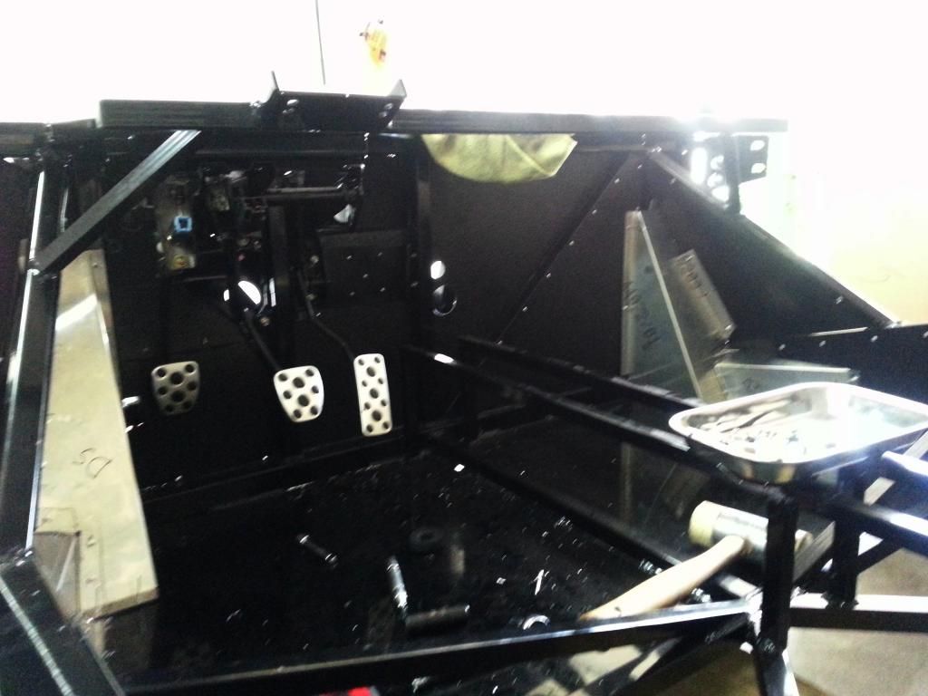
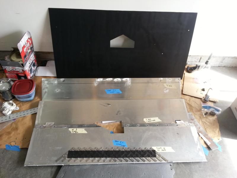
    I haven't had an opportunity to hook up the gas pedal yet. I want to get the cable mounted to the firewall before bolting up the gas pedal.

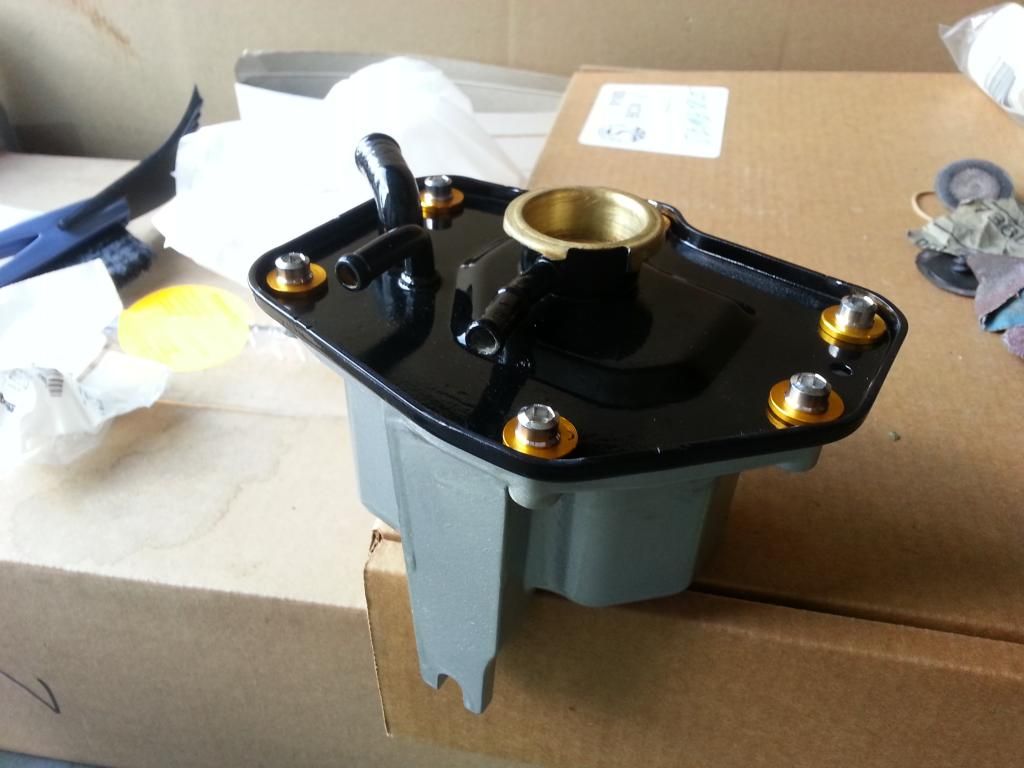
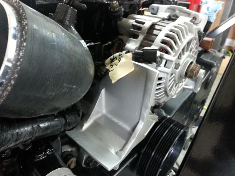
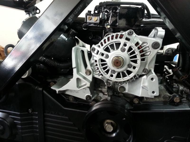
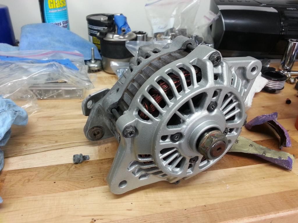
    Alternator turned out ok. I painted the front cover and just cleaned the rear half. If I let myself get caught up in making every single part look perfect then I'll never get to drive it.


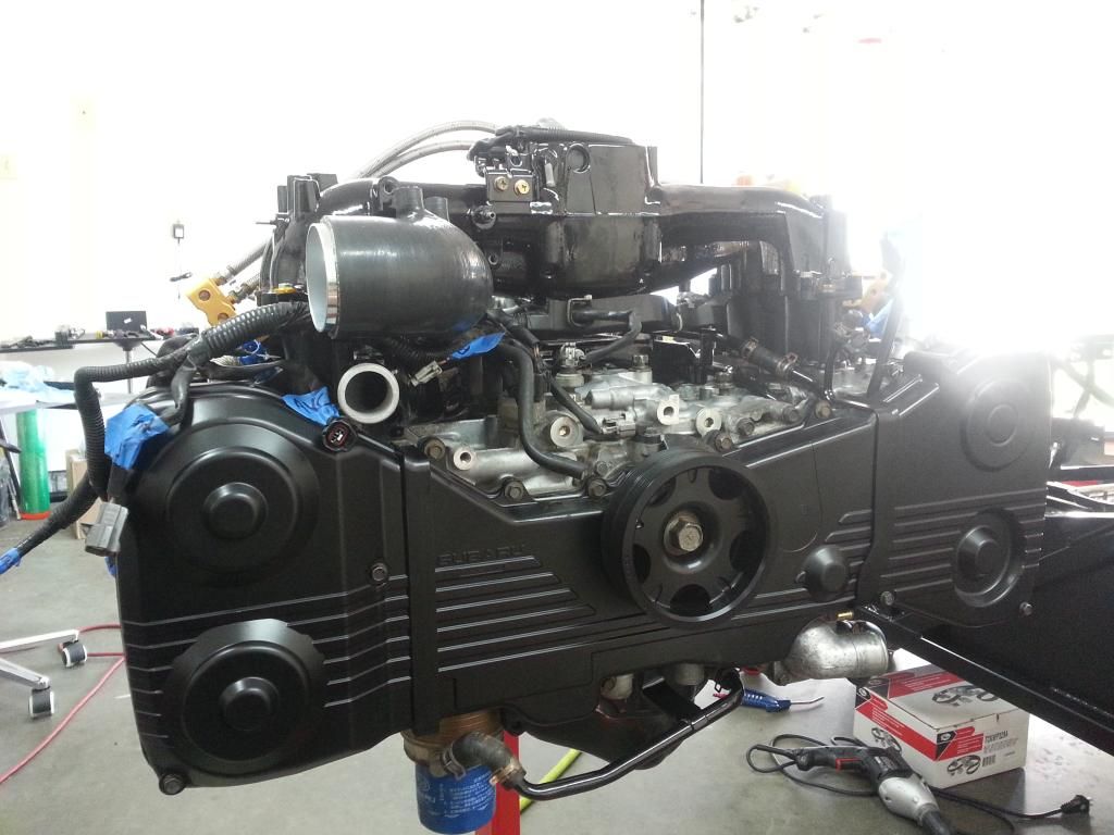
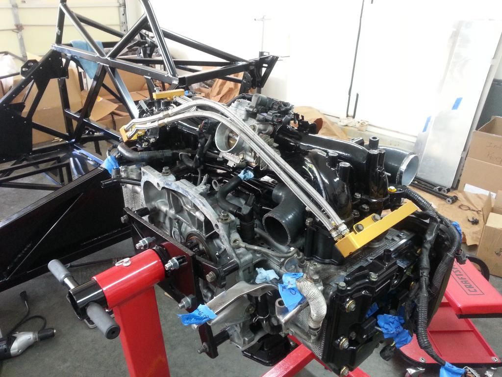
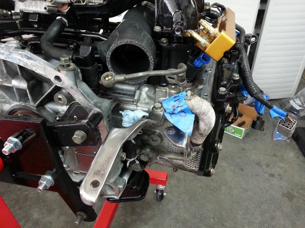
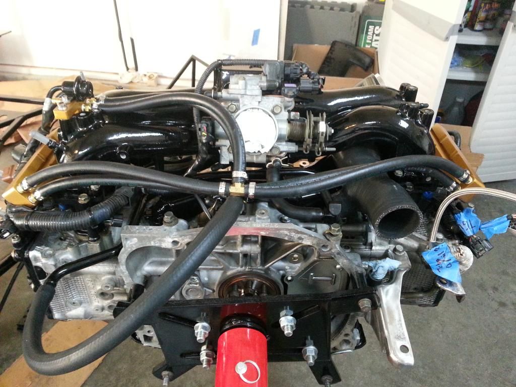
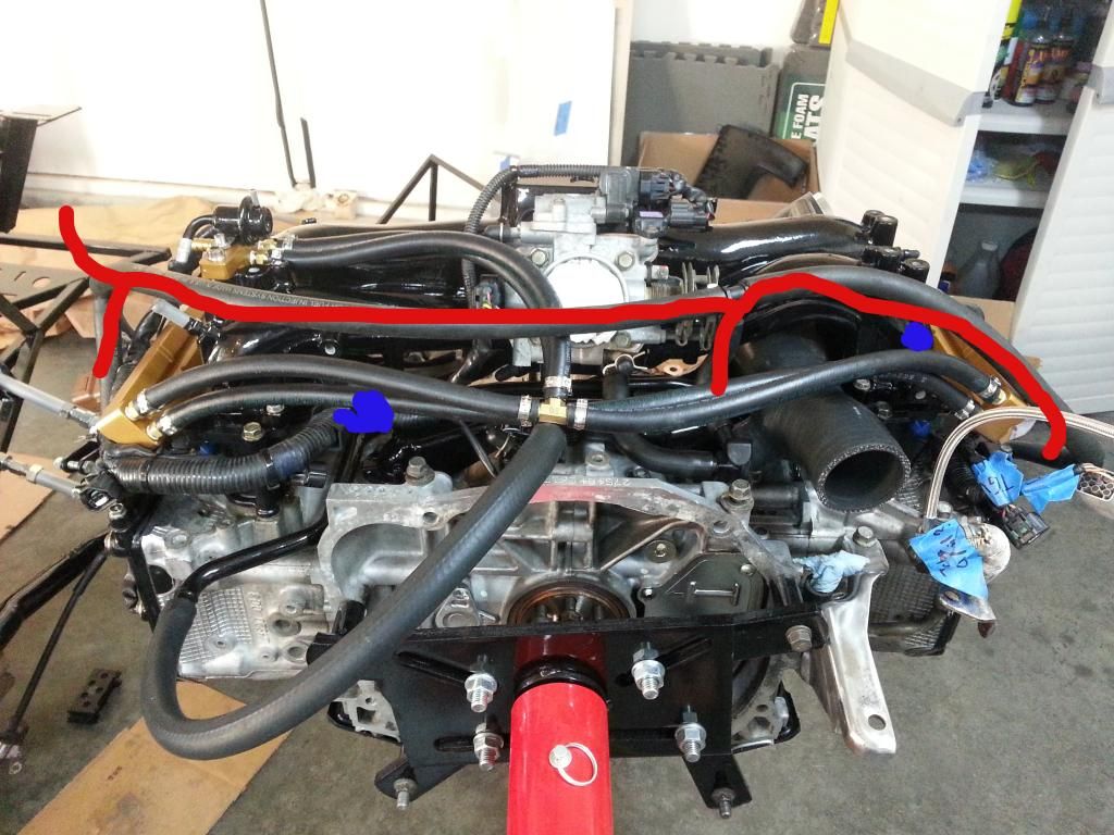
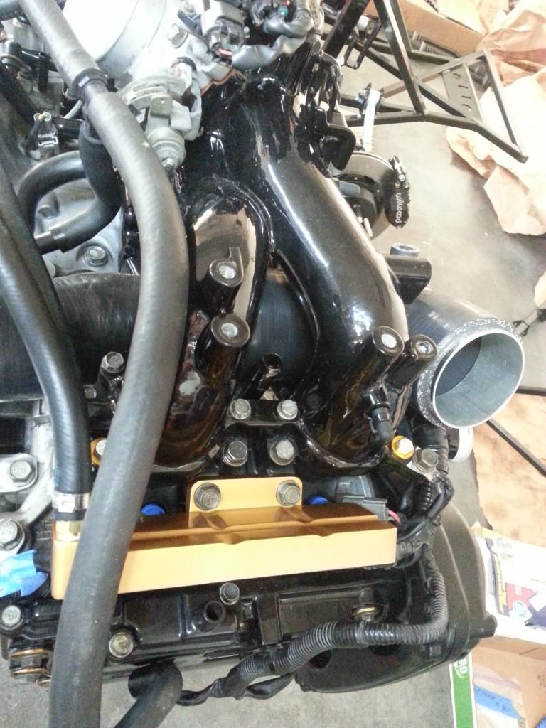
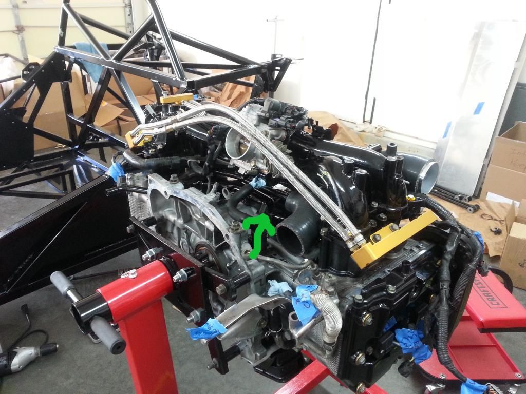
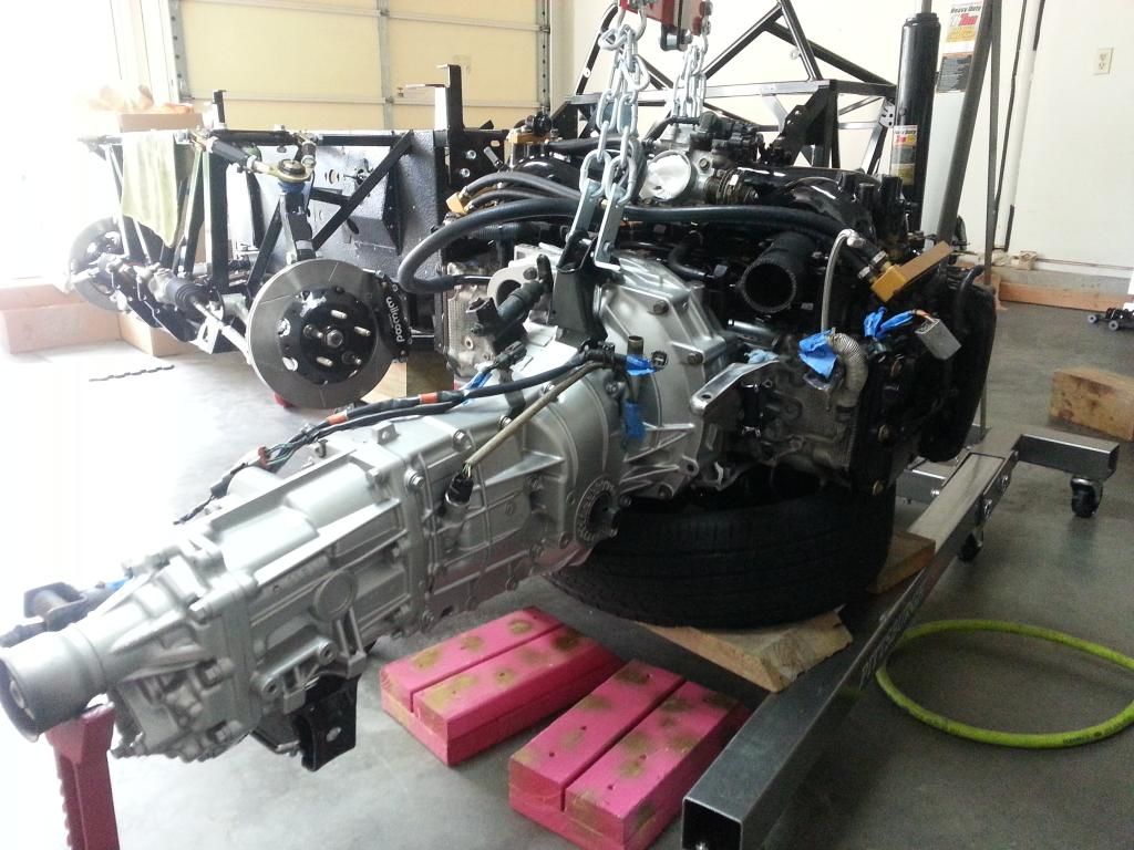
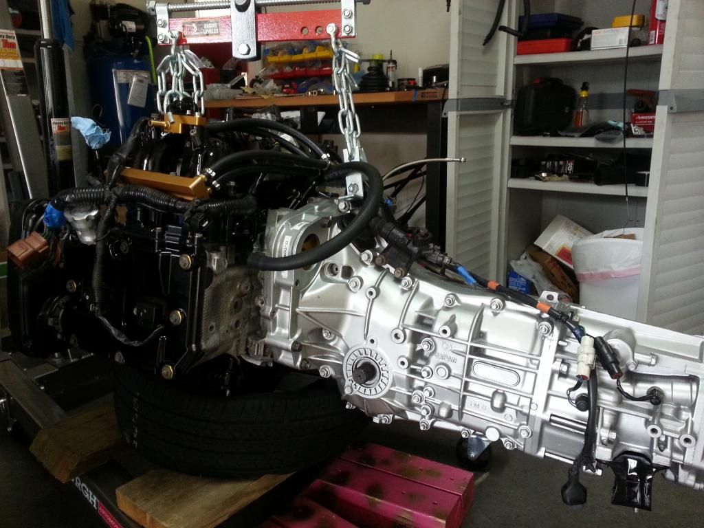
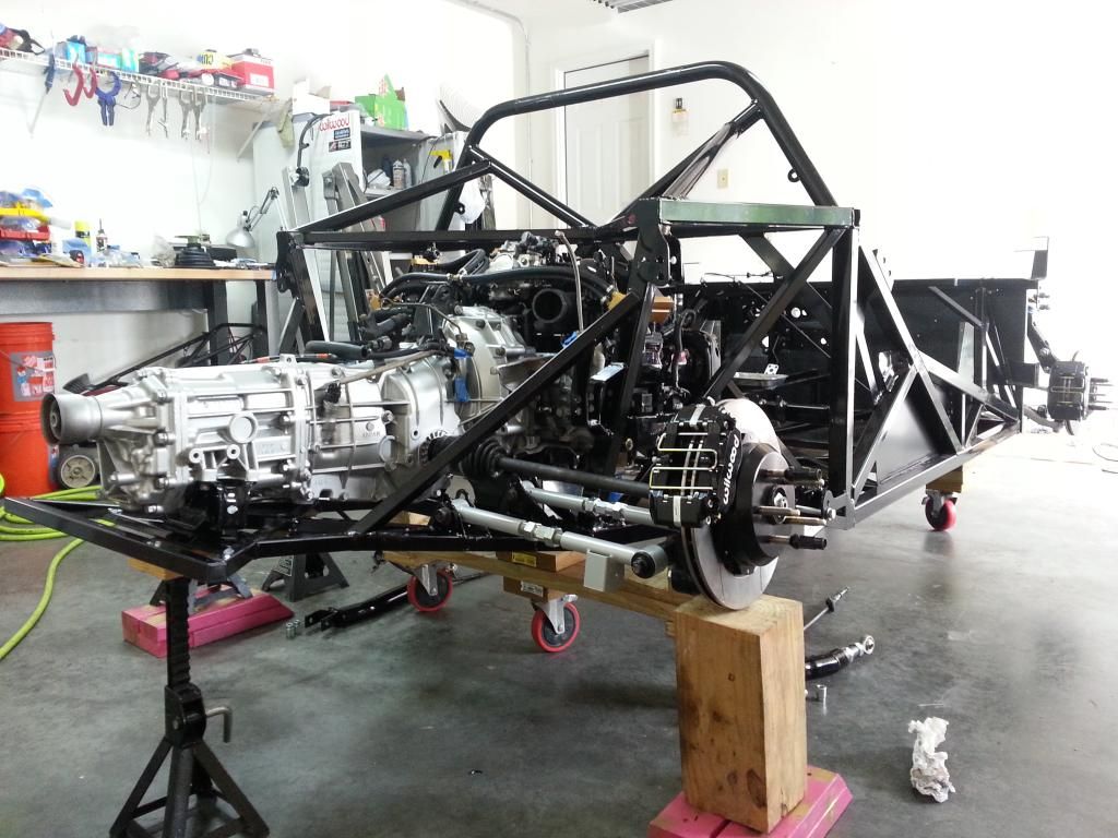
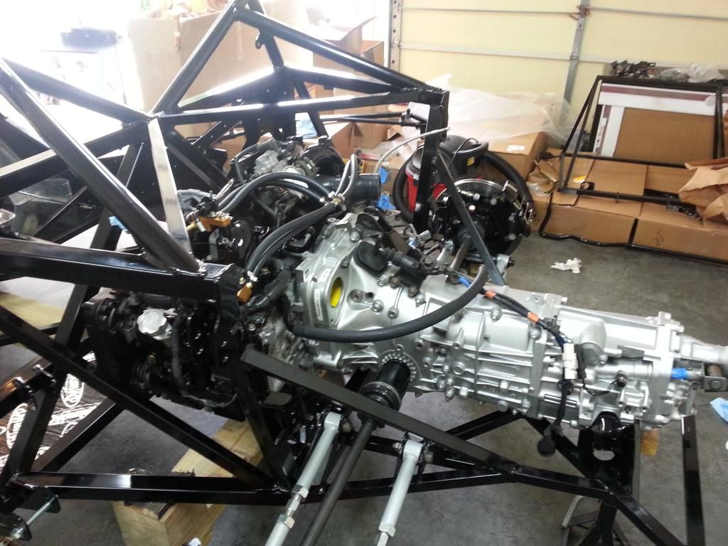
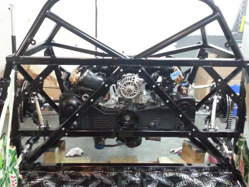
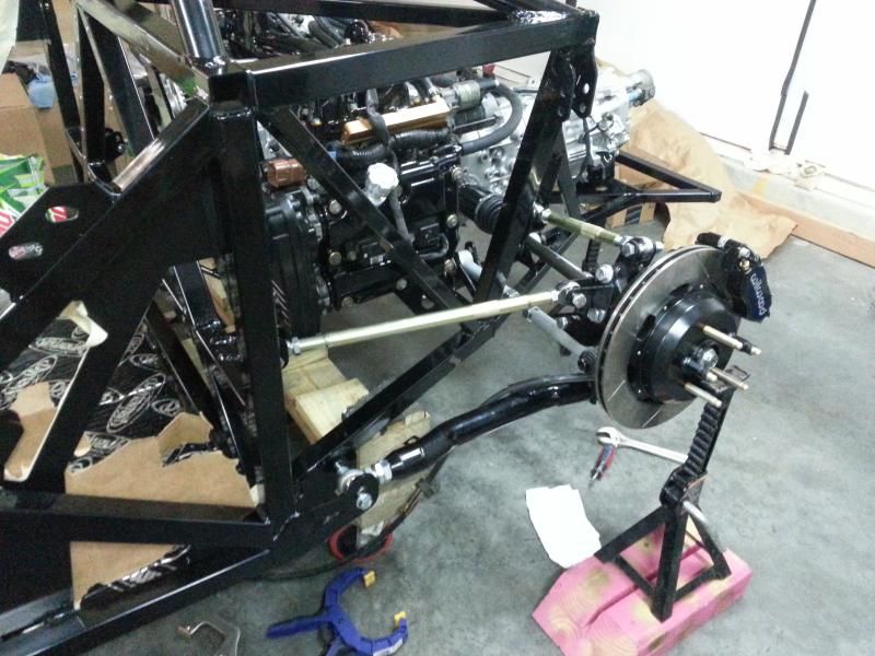
    The engine assembly is slowly coming back together. The coolant tubes are mostly re-installed. I've come across a few things I need to continue putting the engine back together.

    The intake manifold mounting bolts have been massaged to play nicely with the TGV deletes.

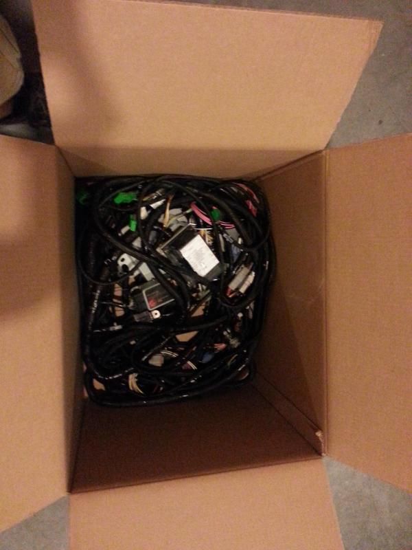
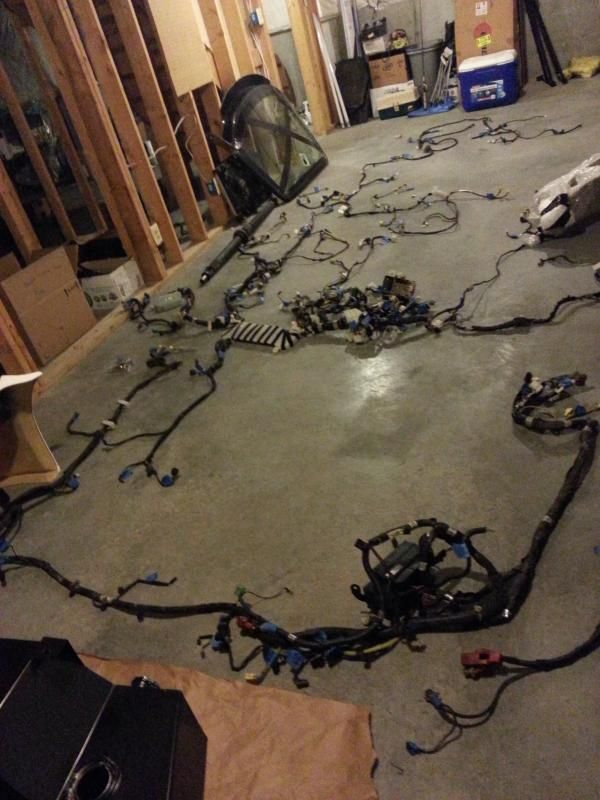
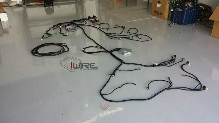
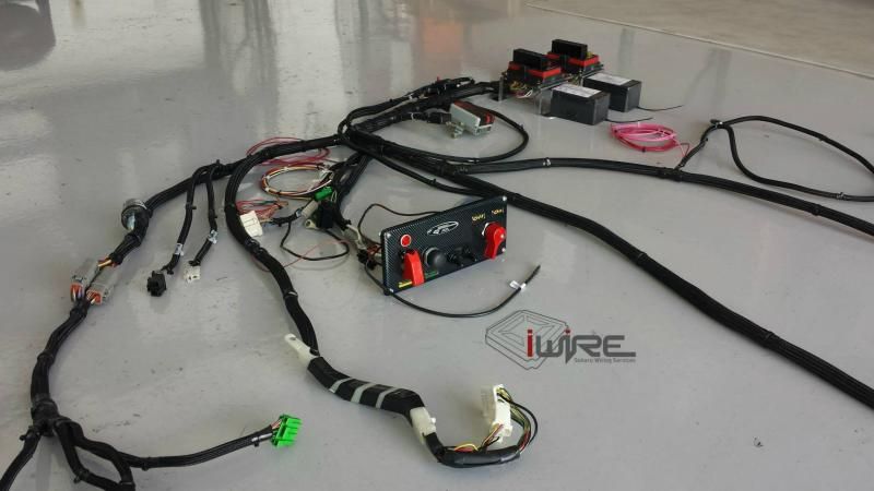
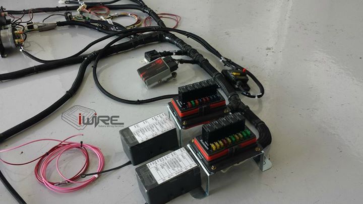
    This week I did decide to bite the bullet and have Brian at iWire build me a custom harness. His work is very impressive and I'm looking forward to seeing the final product. It'll save me a lot of time in getting to go kart stage as well as clean up the install. 55 pounds of harness have already been shipped out. Looking forward to see what it weighs when it comes back.

  2. #122
    Moonlight Performance
    Hindsight's Avatar
    Join Date
    May 2014
    Location
    Atlanta
    Posts
    3,402
    Post Thanks / Like
    Woah, had no idea the harness weighed so much!

  3. #123
    Senior Member metros's Avatar
    Join Date
    Jun 2013
    Location
    NoVA
    Posts
    1,064
    Post Thanks / Like
    Build Update:

    The build is finally starting to show some signs of progress. The suspension is mostly in place, front brakes are done, rears are in the process, engine is starting to come together, and the wiring harness is being built by a pro.

    Engine:


    Coolant reservoir - painted and put together with splashes from the engine color scheme (black/gold).


    55# box of wires: 2002 wrx wiring harness


    Unfortunately the fuel rails were previously anodized, which didn't hold the gold paint on it very well. The paint cracked and started to flake when I tightened the bolts down. Might as well get them professionally anodized gold now before the engine is in the car.

    I'm happy to report the replacement APR gtc300 has arrived safely. I'm also happy that Factory Five has replaced the one out of place carbon side strake that wasn't second generation. I paid for shipping both ways (which I offered) to make it a more square deal for both of us.

    The rear brakes I'm working with Wilwood on. The rears aren't designed to be adjustable and the brake pads end up being mounted with 1/8" of brake pad outside of the rotor diameter. I'm afraid down the road it'll eat up brake pads because they'll be crumbling off that extra lip continuously.

  4. #124
    Senior Member metros's Avatar
    Join Date
    Jun 2013
    Location
    NoVA
    Posts
    1,064
    Post Thanks / Like
    Been a rough few weeks as far as progress goes. Last weekend I needed to revamp a few things which required me removing the intake manifold and TGV deletes - again. I have since successfully made the adjustments and put everything back together.

    I didn't find a lot of easy anodizing access within the immediate area. I decided to give it another go with the paint and really put some hours into making sure the outcome was better this time. I found that using the 3m prep pads on my die grinder I could get down past the anodizing to bare aluminum without being too aggressive. Then I used the metal etching spray and overall came out with a good quality product.

    Stripped:
    I spent hours stripping these down to get rid of all the anodizing material on the surface. I wish I had access to a media blaster. I had to use small files to reach into the corners to make sure the paint surface was uniform.

    I actually thought about keeping these bare aluminum look by just clear coating them. But the gold looks really good and is going to tie some of the exterior details into the engine bay.


    Finished:
    After being cured in the oven for an hour at 200*.


    Rear Wilwood Brakes:
    They're done for the time being. The final outcome of working with Wilwood on the fitment was that Wilwood wasn't going to do anything. Wilwood claims they knew the fitment wasn't perfect but chose to produce the kit using these parts due to their high volume of use within the company. This way they could keep costs low by pulling parts off their shelf instead of investing into development. Completely understandable - However, I think they could've made the kit fit perfectly if they had put just a little time into developing it, which wouldn't have taken a large financial investment.

    Here is a link to the actual email and thread if you're interested in their word for word response.
    http://thefactoryfiveforum.com/showt...lignment/page2

    For the time being I'll have to bevel the outer edge of the brake pads to prevent them from crumbling and killing pad life.


    Gas Pedal Mount - revision #4
    One of the lucky few 818 owners that has gotten his car on track has reported back that the firewall started to separate when he got back on the gas quickly. I've revised my mount to tie into the frame on both sides to prevent deflection/separation from the frame. I'll post pictures when it's finished, again.

  5. #125
    Senior Member AZPete's Avatar
    Join Date
    Feb 2011
    Location
    Scottsdale, AZ
    Posts
    2,374
    Post Thanks / Like
    Huh? Gas pedal mount / firewall separation / separation from the frame? Please explain more about this.
    818S/C : Chassis #25 with 06 WRX 2.5 turbo, ABS, cruise, PS, A/C, Apple CarPlay, rear camera, power windows & locks, leather & other complexities. Sold 10/19 with 5,800 miles.
    Mk3 Roadster #6228 4.6L, T45, IRS, PS, PB, ABS, Cruise, Koni's, 17" Halibrands, red w/ silver - 9K miles then sold @ Barrett-Jackson Jan 2011 (got back cash spent).

  6. #126
    Senior Member metros's Avatar
    Join Date
    Jun 2013
    Location
    NoVA
    Posts
    1,064
    Post Thanks / Like
    Many of us have tossed the FFR gas pedal mount aside and decided to mount the gas pedal directly to the firewall. CPlavan or Brando (I forget which) reported that the firewall started to pull away from the frame after being on track and transitioning to the gas too hard/quickly.

    The mount I'm crudely putting together will tie the frame into the gas pedal mount, which will hopefully prevent any future issues.

  7. #127
    Senior Member metros's Avatar
    Join Date
    Jun 2013
    Location
    NoVA
    Posts
    1,064
    Post Thanks / Like
    Made a little bit of forward progress today.

    I had planned on re-installing the freshly painted fuel rails with new lines over this weekend. However, Perrin customer service told me the wrong size fuel line 3/8 for my v1 fuel rails. So I'm awaiting 8 new 1/8 npt to 3/8 hose barb fittings to use the roll of fuel line that I purchased. It was easier this way than trying to return the fuel line for different size.

    I did create some ground wires for the intake manifold to block. These were necessary because the TGV deletes are composite and prevent the lines grounding on the intake manifold from grounding through the engine block. I also neatened up a few things on the engine and set a few things in place.

    The actual progress worth talking about was getting the gas pedal mount (version 4) finalized and installed as well as the cockpit aluminum panels drilled. The gas pedal mount attaches directly to the frame as well as gets riveted to the firewall. This is to prevent the previously mentioned - foot through firewall problem.


    Can someone identify this line on the right hand side for me? The one with the heat shielding with blue tape on it. I need a replacement but haven't been able to verify the correct part number.


  8. #128
    Mechie3's Avatar
    Join Date
    May 2012
    Location
    Indianapolis
    Posts
    5,174
    Post Thanks / Like
    Its a coolant line for the turbo.
    Zero Decibel Motorsports
    Check out my new website!
    www.zerodecibelmotorsports.com
    www.facebook.com/zero.decibel.motorsports

  9. #129
    Senior Member Frank818's Avatar
    Join Date
    Jun 2013
    Location
    QC, Canada
    Posts
    5,732
    Post Thanks / Like
    Version 4, next version is the one where the pedal mount has concrete poured all over it, so the foot can't go through, unless you are a super hero of some sort with super powers, which you are!
    Frank
    818 chassis #181 powered by a '93 VW VR6 Turbo GT3582R
    Go-karted Aug 5, 2016 - Then May 19+21, 2017
    Tracked May 27/July 26, 2017
    Build time before being driveable on Sep 27, 2019: over 6000h
    Build Completed Winter 2021

  10. #130
    Senior Member Brando's Avatar
    Join Date
    Oct 2013
    Location
    Irvine, Ca
    Posts
    566
    Post Thanks / Like
    Blog Entries
    1
    Quote Originally Posted by metros View Post
    The gas pedal mount attaches directly to the frame as well as gets riveted to the firewall. This is to prevent the previously mentioned - foot through firewall problem.
    Nice. I mounted a 6" piece of 1" x 3" L bracket to the adjacent square tubing to the left of the gas pedal. That fixed the foot through firewall but then the next weakest link exposed itself.
    Without too much pressure the gas pedal will bend. It's happened to me a few times now but fortunately it bends back with a half hearted tug.
    That being said you might want to change to Version 5 on your pedal strategy and add a stopper under your gas pedal.

  11. #131
    Senior Member metros's Avatar
    Join Date
    Jun 2013
    Location
    NoVA
    Posts
    1,064
    Post Thanks / Like
    Good idea on adding a stopper. Where is yours bending? At the top where it pulls the cable?

  12. #132
    Senior Member Brando's Avatar
    Join Date
    Oct 2013
    Location
    Irvine, Ca
    Posts
    566
    Post Thanks / Like
    Blog Entries
    1
    No, it bends between the fulcrum and the pedal.

  13. #133
    Senior Member BrandonDrums's Avatar
    Join Date
    Feb 2011
    Location
    Triangle area, NC
    Posts
    611
    Post Thanks / Like
    I would highly recommend replacing the turbo oil feed line with a flexible braided ss one. The OEM hard-line is practically made for one-time use, after a couple removal/installs of the turbo and the line fatigues. Once it's weakened, even a small bump can cause it to crack pretty easily causing oil to spray everywhere and prompting a massive drop in oil pressure (don't ask me how I know).

    http://www.rallysportdirect.com/Blou...-Oil-Feed-Line

    The only issue is that the casting on the heads can have material that blocks aftermarket banjo fittings the direction that works best since the OEM fitting goes on straight up. Depending on which castings you have, you might need to dremel away some of the excess aluminum from around the oil feed output so you can properly angle the aftermarket fitting.

    Also, you don't really need those turbo mounting brackets IMO. They are somewhat good for keeping some of the turbo's weight off of the up-pipe and header but they practically aren't compatible with any aftermarket turbo, I've done without mine for years with no issue. Any larger turbo will need to sit back a tad because of the larger compressor housing and those brackets would need to be altered and bent to prevent them from actually putting additional stress on the up pipe and header. You're better off supporting the down-pipe with a custom bracket that bolts onto the transmission if you're afraid about the header holding the turbo's weight than dealing with those (also IMO).

    Last edited by BrandonDrums; 08-18-2014 at 12:15 PM.

  14. #134
    Senior Member metros's Avatar
    Join Date
    Jun 2013
    Location
    NoVA
    Posts
    1,064
    Post Thanks / Like
    Thanks for the input. Just ordered an oil line as that line has been used a few times. Might as well change it now and not have to consider the current one as a potential weak point.

    The advice about the turbo support I'll keep in mind. I'll have to see how everything lines up once the manifolds are on. I'm planning on using a Blouch 18g xt.

  15. #135
    Senior Member metros's Avatar
    Join Date
    Jun 2013
    Location
    NoVA
    Posts
    1,064
    Post Thanks / Like
    FINALLY got all the correct fittings and fuel lines. I had the fittings last weekend and then realized I had purchased fuel line meant for carb instead of fuel injection. The carb line is only rated to 45-50psi, where the fuel injection line was rated to 225 psi. That was a must change option. Still using the barricade 3/8" fuel line and 3/8 hose barbs on the fuel rails.


    ^^This is what it looks like now. I still need to figure out some of the vacuum hoses and coolant lines.

    Below is what I need help with:
    1. (Highlighted in red) This line I have from tear down looks to connect each vacuum port on valve covers with PCV in the middle. It also has a straight connector at the end where I'm not sure where it should go. Back to the perrin turbo intake hose?

    2. Coolant connections - (Highlighted in blue) 1 is passenger side pointing up between the intake manifold runners. 2 is off of the heater supply hose, also pointing straight up.

    3. Fuel pressure regulator - where should I supply vacuum from for this?

    4. What do I use the rest of these vacuum nipples for on the Perrin turbo inlet?


    Anything else that looks out of place or as if I forgot something? As you can see I'm not planning on using the evap system, which leaves most of that mess capped off.


    FYI, I have the alternator mounts trimmed down as necessary and ready to install to help move the engine into place. Then they'll be coming back off to get painted before final install.

    If everything looks mostly in place then I'm going to install the clutch/flywheel and put the engine and trans in this week.

    Also got around to installing some sound deadening for under the gas tank. Should prevent any squeaking between the gas tank/floor.

  16. #136
    Senior Member metros's Avatar
    Join Date
    Jun 2013
    Location
    NoVA
    Posts
    1,064
    Post Thanks / Like
    Input on the vacuum lines from some of you subaru experts?

  17. #137
    Mechie3's Avatar
    Join Date
    May 2012
    Location
    Indianapolis
    Posts
    5,174
    Post Thanks / Like
    2.0L engine?

    If yes, you have a single line coming off of the valve covers. These go to the hardline on the front of the intercooler which is a very long T essentially. The end of the T goes into the turbo inlet.

    Pull vacuum/pressure for the FPR anywhere off the manifold. Use the now capped brake boost port.

    The two small coolant connections are likely for the throttle body. Just loop these together or weld them shut. No need to heat up the throttle body.
    Zero Decibel Motorsports
    Check out my new website!
    www.zerodecibelmotorsports.com
    www.facebook.com/zero.decibel.motorsports

  18. #138
    fasterer and furiouser longislandwrx's Avatar
    Join Date
    Aug 2012
    Location
    Long Island
    Posts
    2,540
    Post Thanks / Like
    Blog Entries
    6
    In a wrx the turbo inlet vacuum lines are from the boost control solenoid, valve cover vents, the evap solenoid return, and the crank case vent (also the bov return line)


    what are you using for boost control?

    You'll need to plug the evap one

    the valve cover vent or crank case one will go to the vacuum side of your catch can.

    depending on how you set up you venting, there are a lot of ways to set this up. if you are not using a catch can, use a t for valve covers to the inlet and run the crank vent from the pcv to the inlet.
    Last edited by longislandwrx; 09-04-2014 at 07:20 AM.
    A well stocked beverage fridge is the key to any successful project.

  19. #139
    Senior Member metros's Avatar
    Join Date
    Jun 2013
    Location
    NoVA
    Posts
    1,064
    Post Thanks / Like
    Thanks for the help fellas. This is more complicated to me because the donor came with a FMIC and many of these lines deleted or modified.

    Mechie -
    As I understand it:
    -Each valve cover vent comes together and into the turbo inlet with 1 connection point.
    -The FPR receives vacuum from the IM.
    -Loop or cap the coolant lines.

    That leaves me with one question. What do I do with this - green arrow. One of the rubber hoses connects to the PCV on the intake manifold. The other rubber hose goes?


    I think the previous owner had it routed so that the valve cover vents and this rubber hose all went into the turbo inlet with one junction. Is that an issue or going to harm anything?

    LongIsland:
    I'm planning on running a catch can. But I'm anticipating that will be easier to set up once I have the basics correctly in place.

    I'll be using a 3-port electric boost control solenoid.

  20. #140
    Mechie3's Avatar
    Join Date
    May 2012
    Location
    Indianapolis
    Posts
    5,174
    Post Thanks / Like
    The green line tees between the crank case vent, the PCV valve on the manifold and on the turbo inlet. Don't know offhand if you can loop all together as flow is reversed at times in different areas.
    Zero Decibel Motorsports
    Check out my new website!
    www.zerodecibelmotorsports.com
    www.facebook.com/zero.decibel.motorsports

  21. #141
    Senior Member metros's Avatar
    Join Date
    Jun 2013
    Location
    NoVA
    Posts
    1,064
    Post Thanks / Like
    Thanks for the help^^^

    Made some decent headway this weekend. I installed the ACT light flywheel, ACT HDSS clutch, new throwout bearing and new pilot bearing. Also mated the transmission with the engine, which was more of a wrestling match than I had anticipated. Next weekend I'll be able to drop the engine/trans into the chassis and feel some accomplishment.


    Feels good, man.

  22. #142
    Senior Member metros's Avatar
    Join Date
    Jun 2013
    Location
    NoVA
    Posts
    1,064
    Post Thanks / Like
    Got the engine/trans into the chassis this weekend. That was extremely satisfying. The engine is by no means complete, but felt great to get it put into its final location. Now I can paint the alternator mounts and finish up a few of the vacuum hoses that haven't been finished yet. This weekend I was also able to get the throttle cable in place. I previously found that my shipped throttle cable was defective as the threads broke off while tightening the hardware onto it.


  23. #143
    Senior Member Frank818's Avatar
    Join Date
    Jun 2013
    Location
    QC, Canada
    Posts
    5,732
    Post Thanks / Like
    Tnx for the pix metros, exactly what I needed to see at this time of my build. Couldn't be any better, absolutely perfect timing.
    Frank
    818 chassis #181 powered by a '93 VW VR6 Turbo GT3582R
    Go-karted Aug 5, 2016 - Then May 19+21, 2017
    Tracked May 27/July 26, 2017
    Build time before being driveable on Sep 27, 2019: over 6000h
    Build Completed Winter 2021

  24. #144
    Senior Member metros's Avatar
    Join Date
    Jun 2013
    Location
    NoVA
    Posts
    1,064
    Post Thanks / Like
    I saw the fitment issues you were having. Let me know if you want any measurement or specific pictures.

  25. #145
    Senior Member mikeb75's Avatar
    Join Date
    Sep 2013
    Posts
    685
    Post Thanks / Like
    very nice! Looks like you've hit a major milestone.
    818SC chassis #206 EJ207 2.0L VF37 twin scroll || Cusco type RS 1.5 LSD || Wilwood pedal box (firewall attach) || Wilwood superlite front calipers
    BUILD Phase 1: 6/6/2014 car delivered || 5/24/2015 first start || 6/7/2015 go karted || 4/20/2016 hard-top-topped || 10/25/2016 registered || 11/18/2016 inspected & complete
    BUILD Phase 2: 3/8/2017 EJ207v8 || 5/29/2017 re-first re-start || 7/17/2017 re-assembled with race car bits

  26. #146
    Senior Member metros's Avatar
    Join Date
    Jun 2013
    Location
    NoVA
    Posts
    1,064
    Post Thanks / Like
    Feels really good to see things actually going onto the car now instead of just on the engine stand.

    This weekend I was able to make some decent progress and button up a lot of little things that weren't quite finished yet.

    -Installed new OEM roll pins in the axles. Got everything to play nice together finally there too.

    -Painted/Installed the modified alternator mounts.

    Driver side mount remained original. Passenger side mount was trimmed considerably to clean things up.

    Before:


    After: Painted and mounted


    -Installed starter.

    -Gas Tank - assembled the fuel pump hanger with Deatche Werks 200 and installed in gas tank. Also installed the float sensor and vent. Gas tank is almost ready for final install. Next weekend I need to build the heat shield between engine/gas tank. The actual firewall is between driver and gas tank.


  27. #147
    Senior Member Frank818's Avatar
    Join Date
    Jun 2013
    Location
    QC, Canada
    Posts
    5,732
    Post Thanks / Like
    Nice stuff man, nice stuff, keep on coming!
    Frank
    818 chassis #181 powered by a '93 VW VR6 Turbo GT3582R
    Go-karted Aug 5, 2016 - Then May 19+21, 2017
    Tracked May 27/July 26, 2017
    Build time before being driveable on Sep 27, 2019: over 6000h
    Build Completed Winter 2021

  28. #148
    Senior Member
    Join Date
    May 2012
    Location
    Suisun City, CA
    Posts
    851
    Post Thanks / Like
    What are you using to adjust the tension on the alternator belt, since you remove the tensioner bolt?
    818S - #67 (SOLD IT!)
    Delivered: 18 November 2013
    Go Karted: 29 December 2013
    Titled/Registered: 28 March 2014
    Finished: NEVER!
    341 hp @ 4844 RPM / 389 tq @ 3717 RPM

  29. #149
    Senior Member metros's Avatar
    Join Date
    Jun 2013
    Location
    NoVA
    Posts
    1,064
    Post Thanks / Like
    I have a few ideas, but haven't tested them yet.

  30. #150
    Senior Member Bob_n_Cincy's Avatar
    Join Date
    Sep 2012
    Location
    Cincinnati OH
    Posts
    3,904
    Post Thanks / Like
    Quote Originally Posted by JeromeS13 View Post
    What are you using to adjust the tension on the alternator belt, since you remove the tensioner bolt?
    On old Chevy's, You just pry it up and tighten the bolt.

  31. #151
    Senior Member metros's Avatar
    Join Date
    Jun 2013
    Location
    NoVA
    Posts
    1,064
    Post Thanks / Like
    That was my first and easiest thought.

  32. #152
    Senior Member metros's Avatar
    Join Date
    Jun 2013
    Location
    NoVA
    Posts
    1,064
    Post Thanks / Like
    Had a pretty productive couple of weekends. Have I mentioned how nice it is to see parts going on the car now?

    Last weekend I created this heat shield/firewall that goes between the engine and gas tank. There are many cross bars in this location but nothing preventing the gas tank from getting hot due to engine heat. I designed it purposely to not reach the top bar and interfere with the actual firewall that FFR provides as well as the harnesses I'm planning on using.

    Said area between gas tank and engine:


    Firewall/heatshield: Made from 18 gauge steel. The hole in the middle is to allow wiring/fuel lines to connect with the engine.


    Factory Five Racing Firewall:
    This firewall goes between passenger compartment and gas tank. It's made from 1/8" aluminum.

    Mocked up for marking and figuring out where to slot for harnesses.


    Drilled and ready for rivnuts/powder coating.


    Assembled and installed the last links of the rear suspension. Just have to install the Koni shocks now. Before I can do that I need to do the adjustment procedure to make sure they're set equally and appropriately.


  33. #153
    Senior Member metros's Avatar
    Join Date
    Jun 2013
    Location
    NoVA
    Posts
    1,064
    Post Thanks / Like
    My harness came back in from Brian at iWire! Words cannot express the quality that goes into these harnesses. I sent out a large box packed to the brim with the stock wiring harness to the tune of 55#. I received back a completely new harness (with a few connectors re-used) built specifically for my needs. It gets rid of all the un-necessary wires, uses the correct length of brake line wiring without additional splices, organizes the fuse box in a clean manner, and comes with an incredibly sexy control panel for the cockpit. As if that wasn't enough, it also saves me a ton of labor time, which is hard to come by nowadays.

    Received box of wires:


    Control panel:


    From this:


    To this:

  34. #154
    Senior Member metros's Avatar
    Join Date
    Jun 2013
    Location
    NoVA
    Posts
    1,064
    Post Thanks / Like


    I love helping my Dad.

    Last edited by metros; 10-05-2014 at 07:03 PM.

  35. #155
    818 builder metalmaker12's Avatar
    Join Date
    Mar 2012
    Location
    Exeter R.I
    Posts
    2,834
    Post Thanks / Like
    Blog Entries
    1
    Very nice harness
    818S frame #13 Jdm version 8 ej207

  36. #156
    Senior Member Frank818's Avatar
    Join Date
    Jun 2013
    Location
    QC, Canada
    Posts
    5,732
    Post Thanks / Like
    Quote Originally Posted by metros View Post
    I love helping my Dad.

    Watch out, you think he's helping but check his hands! Perfectly clean! I say he's cheating on you.
    And the dog doesn't care about all that.
    Frank
    818 chassis #181 powered by a '93 VW VR6 Turbo GT3582R
    Go-karted Aug 5, 2016 - Then May 19+21, 2017
    Tracked May 27/July 26, 2017
    Build time before being driveable on Sep 27, 2019: over 6000h
    Build Completed Winter 2021

  37. #157
    Senior Member STiPWRD's Avatar
    Join Date
    Jan 2014
    Location
    Leesburg, VA
    Posts
    1,624
    Post Thanks / Like
    Great progress man, had a chance to use that eastwood brake flaring tool yet? I'm getting close to running the brake lines and was hoping to borrow it for a weekend.

  38. #158
    Senior Member metros's Avatar
    Join Date
    Jun 2013
    Location
    NoVA
    Posts
    1,064
    Post Thanks / Like
    Haven't had an opportunity to use it yet. I'm trying to get everything necessary in place first so I know what I need to work around. You're still welcome to borrow it to run your lines.

  39. #159
    Senior Member STiPWRD's Avatar
    Join Date
    Jan 2014
    Location
    Leesburg, VA
    Posts
    1,624
    Post Thanks / Like
    Great, I'll email you. Just wanted to make sure I didn't hold you up.

  40. #160
    iWire's Avatar
    Join Date
    Jan 2014
    Location
    Lake Forest, CA
    Posts
    287
    Post Thanks / Like
    Quote Originally Posted by metros View Post
    My harness came back in from Brian at iWire! Words cannot express the quality that goes into these harnesses. I sent out a large box packed to the brim with the stock wiring harness to the tune of 55#. I received back a completely new harness (with a few connectors re-used) built specifically for my needs. It gets rid of all the un-necessary wires, uses the correct length of brake line wiring without additional splices, organizes the fuse box in a clean manner, and comes with an incredibly sexy control panel for the cockpit. As if that wasn't enough, it also saves me a ton of labor time, which is hard to come by nowadays.
    Glad you're happy Jason! Let me know how the install goes.

    Quote Originally Posted by metalmaker12 View Post
    Very nice harness
    When we say to our customers "if there is anything you need, please ask," we mean it.
    iWire Subaru Wiring Services
    Over 100 Custom 818 Wiring Harnesses Built
    http://www.iwireservices.com/factory...18-wiring-kits
    [email protected]

Page 4 of 13 FirstFirst ... 23456 ... LastLast

Tags for this Thread

Posting Permissions

  • You may not post new threads
  • You may not post replies
  • You may not post attachments
  • You may not edit your posts
  •  

Brown County Customs

Visit our community sponsor