Visit our community sponsor

Thanks:
0

Likes:
0
-
Senior Member

818R Suspension and the Steering Rack
Inspired by a question in another thread:

Originally Posted by
Scargo

"Running the low ride height requires the use of a bumpsteer kit because the steering rack stays in the same chassis location." Does this mean that the steering rack can't be moved up to stay in plane
Rather then install a 25mm bumpsteer kit to make up for the drop in height, could we not just move the steering rack up 25mm to correct the geometry?
-
Director of R&D, FFR

You could do that but the steering geometry will be better if you leave the rack where it is and move the outer tie rod. Getting the long tie rods closer to the plane of the longer lower control arm (longer than the upper) is what you want.
Jim Schenck
Factory Five Racing
-
Senior Member
Originally Posted by
Jim Schenck
..the steering geometry will be better if...
I want "better". FFR R&D location it is. One bump steer kit, please!
-
Originally Posted by
Jim Schenck
You could do that but the steering geometry will be better if you leave the rack where it is and move the outer tie rod. Getting the long tie rods closer to the plane of the longer lower control arm (longer than the upper) is what you want.
How is that???
You are moving the rods away from the plane of the LCA if you do the BS kit.
Moving the rack is better.
-
Administrator


Originally Posted by
D K
How is that???
You are moving the rods away from the plane of the LCA if you do the BS kit.
Moving the rack is better.
No you are not, you are keeping the tie rods in the plane of the LCA and raising the spindles with the bump steer kit.
-
Director of R&D, FFR
Adding a bumpsteer kit gives you an adjustable angle plane, you can set it to wherever you want it. Moving the rack would move it away from the height plane of the lower control arm, but if you are saying the two should always be on the same angle plane I disagree. The lower arm and tie rod should only be parallel if they were the exact same height, angle, and the same length when viewed from the front. Usually the best solution does not have the tie rod and lower arm at the same angle because as the tie rod gets closer to the upper arm it is more affected by that movement as well.
In this case moving the tie rod down gets it closer to the height of the longer arm, and since it is a fixed length (determined by your toe setting and the width of the rack) getting it closer to the longer of the two control arms is helpful. If you really wanted to move the rack you could, but it isn't better.
Jim Schenck
Factory Five Racing
-
Senior Member

Jim, can you explain why the rack is positioned .55 inch off center towards the left of the chassis? This ends up with the inner tie rod pivot points different if you center the rack. So you can move the rack to the right .55, use the rack position as is but cheat the rack by turning the wheel .55 to the right, off center or extend the rack 1.10 to the right as Craig and I did to use the rack on center, minimizing bump steer and providing equal turning both ways on our S models
Rack Fix.JPG
Dan
818S #17 Picked up 8/1/13 First start 11/1/13 Go Kart 3/28/14
-
Senior Member
I asked David to move this thread to the 818R Discussion sub forum. Thanks man.
-
Member

I would love to see this discussion continued.
The move is not 25mm as in the first post, but 2 7/16" (62mm). It looks like a lot of twist on the cast ear of the upright. Thinking about a bumpy corner on race rubber makes me nervous. A failure here could be catastrophic at speed.
-
Senior Member
I started this topic in the General section months ago, before Jim Schenck revealed the spacing of the prototype's bumpsteer correction spacing.
Also note that while a spacing of 2 7/16" (~62mm) is recommended it's for the Baer Kit, that's the spacing from bottom of steering arm to top of rod end ball. The spacing from bottom of steering arm to center of pivot point is 2 13/16" (~71.5mm). The Baer Kit rod end ball measures 0.75" at the flats.
-
Senior Member

Originally Posted by
nuisance
I would love to see this discussion continued.
The move is not 25mm as in the first post, but 2 7/16" (62mm). It looks like a lot of twist on the cast ear of the upright. Thinking about a bumpy corner on race rubber makes me nervous. A failure here could be catastrophic at speed.
I hear what you are saying. You have to remember the car is much, much lighter than a stock WRX. Plus, all the "Force" is not on the steering knuckle. If all the "Force" was on the steering knuckle, we would not be able to turn the car very easily.
The majority will be on the LCA ball joint and upright (notice the thick steel and welds).
That being said, the 2 7/16" spacer does act like a lever. Getting hit "just right" I imagine the cast knuckle steering arm would be the first thing to go, or we would just get the wheel stripped from our hands. No different than other race cars out there with cast parts.
I'm not too worried since the factory 818R has been on the track alot (bumpy tracks), and actually went into a Tire wall (Journalist).
Thanks- Chad
818R-SOLD!!!- Go Karted 7/20/14/ Officially raced NASA ST2- 2/28/15
2016 Elan NP01 Prototype Racecar Chassis #20
1969 Porsche 911ST Vintage Race Car
1972 Porsche 911T (#'s matching undergoing nut & bolt resto in my garage)
-
Administrator
Originally Posted by
C.Plavan
I'm not too worried since the factory 818R has been on the track alot (bumpy tracks), and actually went into a Tire wall (Journalist).
It has seen the wall twice :-)
-
Senior Member
Originally Posted by
Wayne Presley
It has seen the wall twice :-)
Do tell, do tell 
Thanks- Chad
818R-SOLD!!!- Go Karted 7/20/14/ Officially raced NASA ST2- 2/28/15
2016 Elan NP01 Prototype Racecar Chassis #20
1969 Porsche 911ST Vintage Race Car
1972 Porsche 911T (#'s matching undergoing nut & bolt resto in my garage)
-
Senior Member
-
Administrator
The magazine guy did it really good and John skimmed it off the tires at Watkins Glen.
-
Tazio Nuvolari wannabe

Complex geometry. How to know what's best and best for bump-steer? Personally, I don't care for the tie-rod end being levered off the steering arm by many inches.
"Best" for me with my current line of thinking is utilizing the upper arm and mount and incorporate racing components as much as possible for a race only (uncompromised) design. Seems many spindles have steering arms at various heights and with varying Ackerman.
For my goals, I plan on doing a different spindle, rack and LCA. I'm hoping I can get the help of a professional on design.
-
Member
Bump steer testing
As Scargo pointed out, it is very complicated geometry. You can buy a $500 program, WinGeo, and enter all the parameters and find values for bump steer, roll centers, etc. Or, you can measure it on your car, which is what I did.
I set the toe at zero at a ride height of 4". Then I moved the upright up and down +/- 2" guessing that it would a good approximation of total travel. I clamped a lazar level to the hub, and shined the dot on the barn door 20 feet away. This way I could measure small changes.
bumpsteer baer.jpg
Some people measure toe in degrees, but I think more commonly it is measured with a 2 foot piece of angle iron laid along a tire on each side of the car. Then, for example, 1/4" of toe out means the front ends of the angles are 1/4" farther apart than the rear ends. This is equal to about .3 degrees of toe out on each wheel.
So, for my setup, the dot on the door moves 20 times more than the front of the angle iron on the tire. Since the rear of the angle moves too, and the tire opposite moves as well, the math works out that the dot on the door moves 5 times more than the actual toe reading.
Now for results (my measurements on my frame at R ride settings), with camber -1 degrees, and castor 4 degrees, set for zero toe at 4" ride height.
For the Baer bumpsteer kit as it comes, using all the spacers, the total spacer length is 1.15"
When the suspension is at 2" extension, there is 2" of toe out. At 2" compression, there is 1.25" toe in.
For a spacer at 2.437", as suggested by Jim Schenck, at 2" extension, there is .6" toe out, and at 2" compression, .4" toe in.
I messed around a while with different spacers, and finally found that
For a spacer of 2.85", at 2" extension, .05" toe out, and at 2" compression, .05" toe out.
I wouldn't be surprised if different frames have small differences in the above.
-
Senior Member

Thank you for taking the time to do this.
By chance did you test at the stock location (no spacers)?
I ran my car briefly at R height and no bumpsteer kit and it was vicious. I'm at 2.4" now but plan to bump it to 2.85" and test as you did.
-
Research Calibrator

-
Director of R&D, FFR
Nuisance,
Your measurment of toe is being thrown off by tire scrub. As the suspension moves up and down the wheels do not stay exactly the same distance apart due to the arc the control arms travel. So even if the steering angle was fixed you would be seeing an arc in your laser pointer dots. My guess is that is the difference between your spacer dimension and what we came up with, however alignment settings can have a significant affect as well because they alter both control arm length (camber) and tie rod height (caster). You can still measure bump steer with a laser pointer you just have to compare a point equal distance out the back side to seperate the turning motion from the scrub motion.
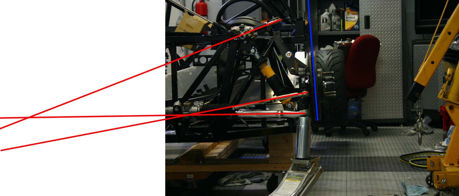
Sponaugle,
In your picture your lines have to pass through the outer pivot points of the lower arms, the Subaru arms are deceptive in that the center of the lower ball joint is not in the arm but is up in the spindle. So your line for the lower arm is way to low on the outside. Moving that line up would give you a much closer intersection like you are talking about.
Jim Schenck
Factory Five Racing
-
Research Calibrator
Originally Posted by
Jim Schenck
Sponaugle,
In your picture your lines have to pass through the outer pivot points of the lower arms, the Subaru arms are deceptive in that the center of the lower ball joint is not in the arm but is up in the spindle. So your line for the lower arm is way to low on the outside. Moving that line up would give you a much closer intersection like you are talking about.
Ah makes sense. I was curious what was the correct place to draw the line. I'll correct them. Thanks!
-
Member
Originally Posted by
Jim Schenck
Nuisance,
Your measurment of toe is being thrown off by tire scrub. As the suspension moves up and down the wheels do not stay exactly the same distance apart due to the arc the control arms travel. So even if the steering angle was fixed you would be seeing an arc in your laser pointer dots. My guess is that is the difference between your spacer dimension and what we came up with, however alignment settings can have a significant affect as well because they alter both control arm length (camber) and tie rod height (caster). You can still measure bump steer with a laser pointer you just have to compare a point equal distance out the back side to seperate the turning motion from the scrub motion.
I just saw this. Jim, you are right of course, I will have to re-do the measurements.
Also Jim, thank you for reading these forums and taking the time to respond!
-
Member
So, I did re-do the measurements. This time I was as careful as I could be. The alignment was -3 camber, 3.6 castor, and 0 toe at ride height of 3.5". I clamped a 2 foot level to the disc, and measured each end to a bar clamped to the frame. This way I would cancel the tire scrub, and measure toe more directly. I then doubled the difference I found so it would be the same as we usually measure from side to side using toe plates. I am still using the Baer bump steer kit rod ends.
With my original spacer of 2.85", 2" compression gave 3/16" toe out, and 2" extension gave 1/32" toe in
With the FFR spacer of 2.437", 2" compression gave 1/16" toe in, and 2" extension gave 1/4" toe out
With a spacer 2.75", 2" compression gave 1/16" toe out, and 2" extension gave 0 toe
Back to building now
-
Tazio Nuvolari wannabe
I'm no suspension geometry expert but I don't understand the small amount of caster. I thought, in many production race cars, (like my STi) that caster was 6+ degrees. I believe 7 may be desirable.
-
Director of R&D, FFR
The difference in Caster is due to the manual steering, with power assist you could run more. A lot of it has to do with steering feel although there are some benefits (camber gain when the wheels are turned) and some compromises (weight jacking when the wheels are turned) to running to much. On a car with so little weight on the front end as an 818 I think you would need to run 8-10 degrees of caster to get any feel into the factory power steering system.
Jim Schenck
Factory Five Racing
-
Member
I will toss in bit of a layman's view here...
In a manual steering car, you feel castor the most when you come out of a turn and lean into the gas and the steering wheel wants to straighten out, and in a tight low speed turn you can let the steering wheel slide through your hands and then catch it as the car straightens out. I am old enough that my first few cars had manual steering so I felt this all the time. With power steering it is more subtle, but still there.
For a racer, and talking about steering feel, it is castor that you pull against when you hold a turn. If you don't have much, it is harder to feel the reduction of that turning "pull" as you get to the limit and the traction is going away. So we would like to have enough castor to provide a good feel, but not so much that makes it hard to steer. So naturally power steering changes the equation.
-
Senior Member

I don't want to hijack the thread but I need to move to the rear suspension for a minute. I mocked up the rear links. With the lateral links at 16 inches the top link is in the short side even with 3 degrees camber. How long are your lateral links after alignment.818 rear link 001.JPG
-
Director of R&D, FFR
Our uppers are right at 9.5 inches, I used the factory arms as jigs to set the length of our lower lateral arms (about 15-3/4) then adjusted the toe with the rear one from there. You want the upper link to be a good bit shorter than the lowers so the suspension gains negative camber in travel.
Jim Schenck
Factory Five Racing
-
Senior Member
That's kind of what I thought, my laterals are at 16 inches so I am going to trim them a little. and that will take care of the upper link. Thanks for the input. DC
 Posting Permissions
- You may not post new threads
- You may not post replies
- You may not post attachments
- You may not edit your posts
-
Forum Rules

Visit our community sponsor


 Reply With Quote