FormaCars

Visit our community sponsor

Thanks Thanks:  0
Likes Likes:  0
Results 1 to 8 of 8

Thread: Chris' Wiring Thread - Old School Carb'd using '65 Mustang and Ron Francis Harnesses

  1. #1
    Out Drivin' Gumball's Avatar
    Join Date
    Feb 2011
    Location
    Blackberry Township, IL
    Posts
    2,653
    Post Thanks / Like

    Chris' Wiring Thread - Old School Carb'd using '65 Mustang and Ron Francis Harnesses

    I had so much fun chronicling my bodywork that I thought I'd start a similar thread for the process of wiring my Mk3.1. Like bodywork, I didn't know a thing about this subject before digging in earnestly about a week ago. I've planned my wiring for quite some time and everything that I've purchased was with an eye towards the end goal of using as much reproduction OEM Ford parts (sourced from the '65 - '66 Mustang parts bin) in conjunction with a Ron Francis harness that came with the kit.

    Since my engine (carb'd 347 that started life in a '94 SVT Mustang) is old-school, and since I have experience with the first generation Mustang, I decided to use as much "plug-and-play" electric parts as possible. In addition to the Ron Francis harness, I'm using the following (reproduction Mustang wiring harnesses were sourced through a restoration place):

    - 60 amp Ford 1G alternator
    - Ford external voltage regulator
    - Ford starter solenoid
    - Pertronix Flamethrower coil with the top painted yellow like the original Ford part and with a Ford decal
    - Original Ford dual point (small cap) distributor with Pertronix ignition module
    - Group 57 battery in Breeze engine compartment tray (added fake fill caps and "Lucas" decals for period correct appearance
    - '65 Mustang "headlight feed" wiring harness (because this is the harness that has the alternator / voltage regulator wiring)
    - '65 Mustang alternator feed wiring harness
    - '65 Mustang "engine gauge feed" wiring harness
    - '65-'66 Mustang ignition switch with plug-in harness pigtail
    - Smiths gauges (mostly mechanical)
    - Various Mustang, MG, Healey, and Triumph switches, pumps, lamps, and accessories that I'll highlight as I go along hooking them all up (and hopefully getting them to work without burning my car to the ground).

    My goal is to combine these harnesses and, once all the cutting and splicing is done, to wrap everything in cloth friction tape for that old-school look.

    Here's what I started with:


    For a guy who knows squat about electrics other than plugging new harnesses in place as I've done during past restorations, this was a very daunting pile of stuff. But, doing the bodywork myself gave me the confidence to tackle this and, like every part of this project, it's not too bad if you approach it one little project at a time. So, instead of looking at the wiring as one big step, I instead decided to deal with it in small individual projects.

    Early in the build, when I made the decision to go with this sort of layout for a period-correct look, I decided to place everything in the engine compartment in a layout similar to the '65-'66 Mustang. Although not correct in comparison to the original cars, this would allow me to utilize the reproduction Mustang wiring harnesses with very little, if any, major surgery. To that end, the alternator is low on the engine to the passenger side, the coil is at the top to the driver's side, the voltage regulator is on the driver's "F" panel, and the starter solenoid is on the passenger's "F" panel. A test fit of the "headlight feed" wiring harness showed that my placement is just about right, with no need to shorten the wiring between the alternator and the voltage regulator, while leaving me enough to tuck the harness underneath the Breeze radiator top - to - body aluminum panel for a clean look.

    Beyond that, I hadn't done much regarding electrics. Rather, I've spent all my time on mechanicals and bodywork. Once the engine was done and the Pertronix was in the distributor, the coil in place, and spark plug wires hooked up, I just hotwired it to get it running, both for first start and for a bunch of go-kart runs. To do that, I simply used a trigger switch jumping from the battery terminal on the starter solenoid to the "S" terminal (small connector on the left front of the solenoid) and a toggle switch wired between the positive terminal on the battery to the positive terminal on the coil. That allowed me to get about 4 - 5 hours of run time on the engine and even drive it around quite a bit! So, that mobility made me lazy and helped me to avoid any further wiring work.

    As many of you will recognize, I was doing as many little projects as I could to avoid starting wiring, but I just plain ran out of other things to do and finally had to dig into this part of the project. I guess if I were using just the Ron Francis harness, I wouldn't have been so concerned, but I had no idea how, where, or why I should connect the Ron Francis harness with the reproduction stuff (or what parts of those harnesses were not needed). For the past few weeks, I've been spending all my shop time reading through wiring books - the Ron Francis manual that comes with the kit, Chilton's and Haynes' manuals, the factory assembly line electrical manual from Ford for the Falcon and first generation Mustang, a Painless Wiring instruction book, and lots of schematics and explanations found on this forum and elsewhere on the 'net. It seemed like too much at first, but eventually it all started making sense and I had no choice but to dig in.

    Before I began, I picked up a good multi-meter. This has proven invaluable in the process of tracing wires in the harnesses. You don't have to spend a ton of money to get a decent one, but you definitely need to have one if you want to do this right. I started by removing the black plastic split-loom cover on the Ron Francis harness. This allowed me to see where each of the wires were routed and made the whole thing much more flexible. Another thing I decided at the outset was that I wasn't going to worry about making it pretty at first... I just wanted to make everything work. This means lots of wires draped everywhere and TEMPORARY crimped connections. All of this will be cleaned up, properly soldered, wrapped, and secured before I install the body.

    Here's the Ron Francis main harness temporarily set in place with the split-loom gone:


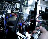
    I started with what I thought was simple - deciding what parts of the '65 Mustang reproduction harnesses were needed. The "headlight feed" harness connects to the main Mustang harness at the firewall and has two distinct parts - one that feeds the headlights, parking/turn signals, and horns and another that runs between the voltage regulator and a three-pronged connector for the alternator feed harness. By stripping off the covering, I found that only two wires ran the full length from the firewall connector to the voltage regulator / alternator branch, so I cut those two and separated that circuit from the one for the lights and horns... one harness down. I'll be using what Ron Francis calls the "Front Harness" to power the headlights, front turn signals, horn, and cooling fan, so all the reproduction Ford stuff for those was sent to the surplus pile. The alternator feed harness then simply plugs into what I now call the "voltage regulator feed" harness. I pulled the alternator off the engine so that I could get a better shot at installing the harness on the back and everything fell into place.

    The black/red wires connect to the ground terminal on the alternator and to the main engine block ground. The white wire connects to the field terminal on the alternator and the yellow/black wire connects to the battery terminal on the alternator. The other end of this harness has a three-pronged plug that simply plugs into the voltage regulator feed harness. Success for the first step - although not yet operational...


    I then connected the flat three-blade plug at the other end of the voltage regulator feed harness to the voltage regulator. The white from the field terminal on the alternator goes to the "F" terminal on the voltage regulator, the black/red goes to ground at the voltage regulator mounting screw, and the yellow/black bypasses the voltage regulator and runs back towards the instrument panel (not hooked up for now - more details to come on this). There are also a couple other wires coming out of the voltage regulator - a solid yellow with a fusible link that goes to the battery terminal on the starter solenoid and a green with red stripe wire that will eventually go to the accessory post on the starter switch (also more to come on this).


    Part 2 of first steps below:
    Later,
    Chris

    "There are no more monsters to fear, and so, we have to build our own."
    Mk3.1 #7074

  2. #2
    Out Drivin' Gumball's Avatar
    Join Date
    Feb 2011
    Location
    Blackberry Township, IL
    Posts
    2,653
    Post Thanks / Like
    I then decided to tackle something substantive that would give me some instant feedback and gratification (if done correctly) - time to wire the ignition switch! This used both the reproduction '65 Mustang "engine gauge feed" harness and the Ron Francis ignition switch circuit. I started by stripping out unnecessary wires from the reproduction Ford harness (heater motor, oil pressure - I have a mechanical Smiths gauge, and coolant temp - ditto). The remaining wires, with the correct push-on connectors on the ends, are a red with blue stripe for the "S" terminal on the starter solenoid (small one on the left front), a brown for the "I" terminal on the starter solenoid (small one on the right front), a black with fusible link (this is what will eventually connect through the ammeter with the aforementioned yellow/black that is coming from the alternator battery terminal to feed charge voltage to the battery), and a red with green stripe for the positive terminal on the coil.

    By simply replacing my earlier hotwiring job with the ignition switch, I figured I'd be able to get the engine to crank, start, and run. This was accomplished by:

    1. Running a 12v feed from the battery terminal on the starter solenoid to the "B" terminal on the ignition switch.
    2. Running a start signal wire (the red with blue stripe) from the "S" terminal on the ignition switch to the "S" terminal on the solenoid.
    3. Connecting the "C" terminal (basically the "run" circuit) on the ignition switch to the orange ignition feed to the Ron Francis fuse panel.
    4. Connecting both the brown and the red with green stripe to the orange "coil" wire coming out of the Ron Francis fuse panel (the one that is bundled with the blue wire and is labeled as "Coil / EFI"

    In sum, when hooked up this way and turned to "ON", the Mustang switch allows 12v power to run from the battery, through the switch, to the fuse panel, and out to the positive terminal on the coil. When the switch is turned to "Start", the solenoid is tripped which allows the starter to crank and a circuit inside the solenoid allows a full 12v feed via the brown wire to the coil. When installed in final fashion the coil feed will have a ballast resistor installed in-line that will reduce voltage to the coil to 7.5 volts in order to avoid overheating the coil (this is original to the '65 Mustang ignition circuit); enough to run the engine, but not necessarily sufficient for strong starts.

    I guess the proof is in the pudding, as they say, so here we go:


    So, now that it cranks, starts, runs, and shuts off with the twist of a key, it's time to tackle the charging system to make sure that it is self-sufficient. Once that's done, I'll dig into all the other circuits one at a time until I have it wired. Lots of fun stuff to come as I have a heater, lots of accessory lights, wipers, a windshield washer system, conversion to single bulb Lucas tail lamps, H4 tri-bar headlamps, etc....
    Later,
    Chris

    "There are no more monsters to fear, and so, we have to build our own."
    Mk3.1 #7074

  3. #3
    Out Drivin' Gumball's Avatar
    Join Date
    Feb 2011
    Location
    Blackberry Township, IL
    Posts
    2,653
    Post Thanks / Like
    Here's another picture I found that shows the layout of the important electrical components in the engine bay. The starter solenoid is in the upper left hidden behind the top radiator hose - just the "S" and "I" terminals are visible. The dark triangle just above the bottom right is a corner of the voltage regulator. The battery is mounted in the Breeze relocation tray as per their instructions - it's actually just a Farm-and-Fleet battery with decals and fake fill caps to make it look old... sort of hiding it in plain sight.

    Later,
    Chris

    "There are no more monsters to fear, and so, we have to build our own."
    Mk3.1 #7074

  4. #4
    Out Drivin' Gumball's Avatar
    Join Date
    Feb 2011
    Location
    Blackberry Township, IL
    Posts
    2,653
    Post Thanks / Like
    So, I had a week off from work on the car due to a trip to Asia for work (Beijing - yuk, due to really bad pollution, Singapore, and Tokyo all in six days) and now it's back to working on wiring.

    After my initial success at being able to start and run the engine from the ignition switch (as opposed to hot-wiring it), I was puzzled about the charging system and power hookup to the main harness using the reproduction '65 Mustang harness. I realized what the problem was after doing a bit of investigation into the differences between the harnesses for '65 Mustangs with gauges versus ones with a charge light. Back when I bought the reproduction harnesses, I went with the "gauge" version as I was putting gauges into my FFR - seemed to make sense to my peanut brain. Well, what I ended up with was a set-up that routed the power wires through the main harness (which I wasn't using) before sending the charge to the battery. Instead, since I'm using mostly mechanical Smiths gauges, I opted for an "as-built" change and replaced the above shown harnesses with the correct ones for a '65 Mustang with a charge light.

    This change gave me a direct wire (the black with yellow stripe) from the back of the alternator to the battery side of the starter solenoid, as well as the correct wiring from the stator terminal on the back of the alternator to the voltage regulator. This also resulted in just two wires going from the charging harness to the dash area - a black with yellow stripe (that connects to the positive terminal on the starter solenoid via a fusible link along with the solid yellow wire that comes from the voltage regulator), which was connected to the "B" terminal on the ignition switch (replacing the hot wire from the solenoid outlined above) and a green wire with red stripe that goes to the charge light - which in turn is connected to the center post (accessory terminal) on the back of the ignition switch.

    I also changed to a solid-state voltage regulator, but drilled out the rivets holding the shallow cover on it and replaced the shallow cover with the original style cover that is "Autolite" stamped.

    With all of these connections made, I checked battery voltage which showed 12v. I then turned the ignition switch to "ON" and the charge light came on. When I turned the ignition switch to "START", the charge light turned off and then stayed off while the car ran. I again checked voltage at the battery and it was now showing 14v - the system was charging - success!!!

    Here are a few new pictures showing the changed wiring harness.

    The new alternator harness, showing the white with black stripe wire for the "Stator" terminal in the foreground:


    New connections at the starter solenoid - note the yellow and black with yellow stripes coming from the lower fusible link (those are going to the voltage regulator and the ignition switch, respectively) and the black with yellow stripe coming from the upper fusible link (that goes direct to the "Bat" terminal on the back of the alternator):


    The fancy new solid-state voltage regulator, though you wouldn't know it but for the black plastic guard covering the connections at the bottom - note that wiring is just laid out for initial connections... this is not the final routing:

    Later,
    Chris

    "There are no more monsters to fear, and so, we have to build our own."
    Mk3.1 #7074

  5. #5
    Out Drivin' Gumball's Avatar
    Join Date
    Feb 2011
    Location
    Blackberry Township, IL
    Posts
    2,653
    Post Thanks / Like
    More successes to report!!! Now that the car starts, runs, and charges all with the simple turn of a key (something I truly will never take for granted again in a production car), I turned my attention to the chassis system. The ignition switch acts as the bridge between the reproduction '65 Mustang harnesses for ignition and charging and the Ron Francis harness by taking battery power through the repop harness and feeding the "accessory" and "run" circuits with switched power. With all that working properly, I wanted to get the rest of the systems up and running. I started by running power to the Ron Francis fuse panel from the "batt" terminal on the starter solenoid. Then, after connecting the front, rear, and dash sub-harnesses, I put a meter on a few wires to check some of the circuits for power. Just for fun, I hooked up the horn (YOWZA - that mini airhorn is loud!), the fuel level (just under a quarter tank of 110 octane left-over race fuel), and the voltmeter (12.5v). These were all good signs that things are starting to fall into place and, more importantly, were small steps towards overcoming my fear of electrics.

    I also learned that I need to add a 510 ohm jumper as a bypass for the charge light - seems that if I don't do that and the light burns out, the charging system will not work. I guess a trip to Radio Shack is in order.

    Oh, and I did a little research on my coil and distributor in relation to the resistor wire mentioned earlier and found that with the Pertronix Ignitor II module and matching Flamethrower coil, no resistor is required. In fact, if installing on a production car, the instructions say to remove that wire.

    Now that the chassis harnesses have power, I'm going to lay out an instrument panel wiring harness to link all my gauges and switches so that things are neat behind the dash.
    Later,
    Chris

    "There are no more monsters to fear, and so, we have to build our own."
    Mk3.1 #7074

  6. #6
    Out Drivin' Gumball's Avatar
    Join Date
    Feb 2011
    Location
    Blackberry Township, IL
    Posts
    2,653
    Post Thanks / Like

    Courtesy lights with FFR-supplied headlight switch

    So this was an interesting one - how to make the single filament / single wire courtesy lamps from a '65 Mustang (1156 bulb), which are grounded by the mounting point and designed to be fed a switched + 12v, operate through the FFR-supplied headlight switch which is a grounding switch.

    The beauty of using this switch is that it operates like an OEM headlight switch - rotate the knob and the gauge lights get brighter until you hit the détente at the end and the courtesy lamps turn on. There is a bare tab on top of the switch near the knob that is the mounting point for the switched wire. Unfortunately, that is a ground switch, not hot.

    To make this all work, I decided to use the grounding switch to activate a relay (I had the one that came from FFR for the cooling fan laying around), then have the relay send + 12v to the lights. I also wanted the courtesy lights to work with the ignition off or on, so I needed a constant hot source.

    Ron Francis to the rescue as their harness includes a "radio memory" lead that provides the constant power source I needed. That wire went to the "86" terminal on the relay and was jumpered to the "87" terminal, too. The "85" terminal was connected to the ground switch terminal on the top of the headlight switch. The final connection was from the "30" terminal on the relay to the lights.

    With everything hooked up, the relay has constant power to it, but doesn't do anything until the headlight knob is rotated all the way. Then, the ground wire to the relay is connected, causing the relay to close (open?) and sending + 12v out from the "30" terminal to the lights - instant courtesy!
    Later,
    Chris

    "There are no more monsters to fear, and so, we have to build our own."
    Mk3.1 #7074

  7. #7
    Out Drivin' Gumball's Avatar
    Join Date
    Feb 2011
    Location
    Blackberry Township, IL
    Posts
    2,653
    Post Thanks / Like
    Well, I haven't been very good about updating this thread, but I have posted quite a few other sub-threads in this forum about parts of my wiring project, including things about the wipers, turn signals, seat heater, etc..., so there are some specific topics for someone to search on if they run into any of the problems / challenges that I did.

    However, I'm now finally at the point where I'm about ready to hook everything up for what may be the last time - that is, if everything works.

    As this thread shows, I started with the process of hooking the ignition switch up, as well as the charging system. Once those functioned, I continued to build upon that success by hooking up and validating separate circuits, such as gauge function, lighting, etc.... As part of that, I stripped any unneeded wires from the Ron Francis harness, added new ones where necessary, and re-tasked others (such as the electric choke 10 amp circuit as a dedicated feed for a 12V outlet). I'm in the process of final routing of the wiring, as well as the installation of hooks/hangars to secure everything. Once those are done, I'll be ready to rivet the rest of the aluminum panels in place and begin working on the interior. The dash is at the upholstery shop for covering now, and I should have that back in a couple of weeks, so I'll post more pics and an update when the dash is back together and installed.

    For now, here is my latest triumph - the dieted Ron Francis main harness ready to be wrapped in friction tape and installed:

    Later,
    Chris

    "There are no more monsters to fear, and so, we have to build our own."
    Mk3.1 #7074

  8. #8
    Carl carlewms's Avatar
    Join Date
    May 2012
    Location
    Nokesville, VA
    Posts
    1,125
    Post Thanks / Like
    Chris,

    Thanks for the updates on wiring...I am going through the same stages with ISIS right now so it is interesting to compare the two installations.

    Carl
    Mk 4 Roadster
    October 25, 2012 - Kit Arrives
    April 8, 2013 - Build Starts
    August 23, 2015 - Rolling Chassis/Engine & Transmission Installed
    March 26, 2016 - Go Cart

Posting Permissions

  • You may not post new threads
  • You may not post replies
  • You may not post attachments
  • You may not edit your posts
  •  

Breeze

Visit our community sponsor