Thanks:
  Likes:


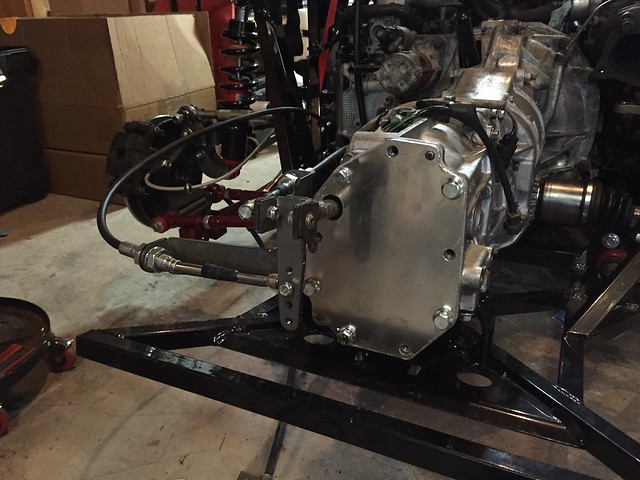
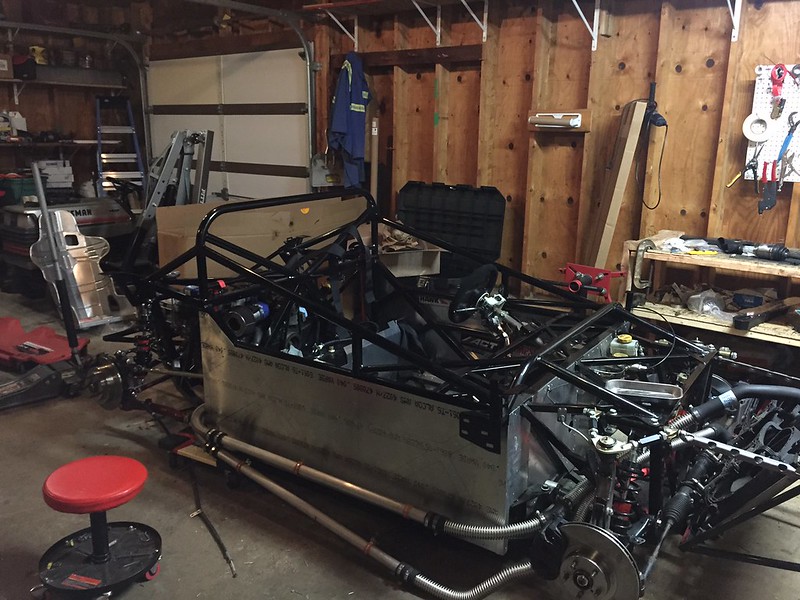
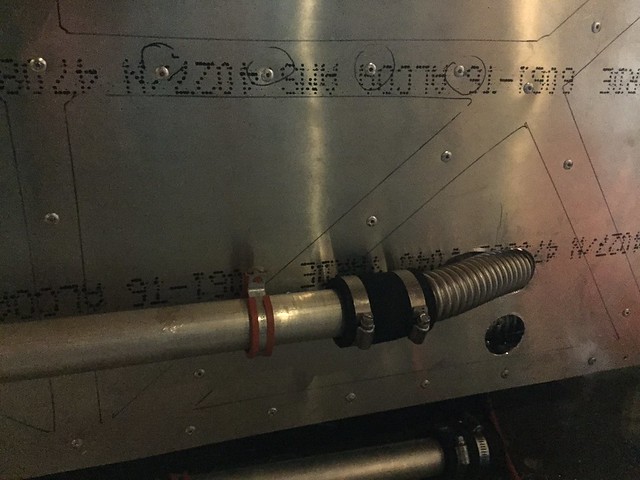
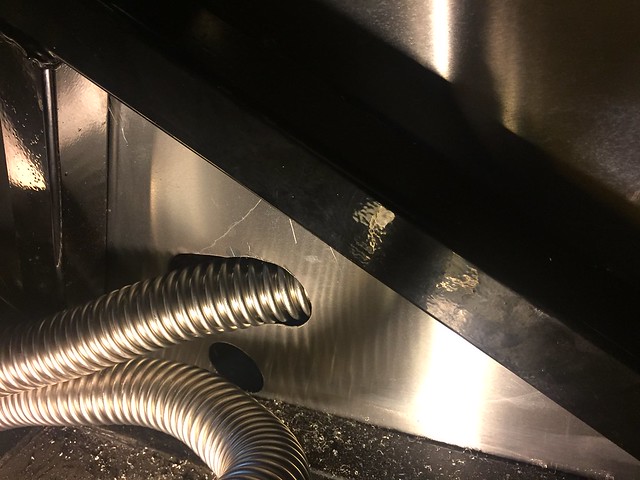
Remounting the hard line bracket on the front side of the tube. That's where I fitted mine after test fitting with my custom length braided lines.
- Home
- Latest Posts!
- Forums
- Blogs
- Vendors
- Forms
-
Links

- Welcomes and Introductions
- Roadster
- Type 65 Coupe
- 33 Hot Rod
- GTM Supercar
- 818
- Challenge Series
- 289 USRCC
- Coyote R&D
- Ask a Factory Five Tech
- Tech Updates
- General Discussions
- Off Topic Discussions
- Eastern Region
- Central Region
- Mountain Region
- Pacific Region
- Canadian Discussions
- Want to buy
- For Sale
- Pay it forward
-
Gallery
- Wiki-Build-Tech

 Reply With Quote