Boig Motorsports

Visit our community sponsor

Thanks Thanks:  0
Likes Likes:  0
Page 2 of 2 FirstFirst 12
Results 41 to 59 of 59

Thread: 2002 WRX harness, pictures of each connector?

  1. #41
    Harley818's Avatar
    Join Date
    Jan 2014
    Location
    Vancouver BC
    Posts
    788
    Post Thanks / Like
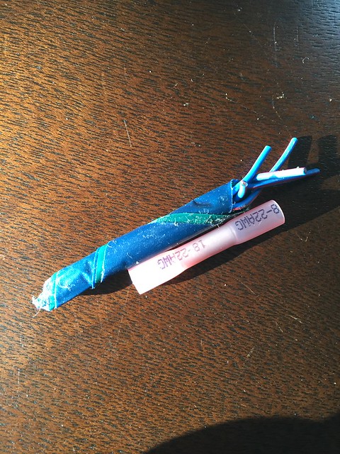
    Yes, I was just isolating it with heat shrink as you are doing.
    Just looking for confirmation that it is the right approach.
    There are a few situations where the normal state would be grounded so I am identifying those and I'll deal with those one at a time once I try to start it up.
    Its a lot easier now before I wrap the wiring and build in the shifter tunnel.

  2. #42
    Harley818's Avatar
    Join Date
    Jan 2014
    Location
    Vancouver BC
    Posts
    788
    Post Thanks / Like
    Wondering if anyone knows what this is? Is it the ambient temp sensor?
    photo 1.JPGphoto 2.JPG

    I am looking for the Ambient Temp sensor attached to F78. Connector is supposed to be two pin black. This one is * (neutral)
    If I find it I might leave it in, otherwise I'll delete it.

  3. #43
    Senior Member EODTech87's Avatar
    Join Date
    Feb 2013
    Location
    Copperas Cove, Texas
    Posts
    207
    Post Thanks / Like
    That's the power window circuit breaker.
    -Jason

  4. #44
    Senior Member Pearldrummer7's Avatar
    Join Date
    Feb 2014
    Location
    Asheville, NC
    Posts
    1,230
    Post Thanks / Like
    I'm trying to remove some of the complexity on the car's wiring. Here's a big on I found that I'm convinced I can do without:


    The original starter circuit involves a relay to disallow starting the car if it's not happy about security (that definitely is getting bypassed), a switch for the clutch to be down (that's a pain in the *** as getting in/out of this car isn't as easy as a normal car), and a relay that locks out starting if the clutch switch isn't down.


    Here's the new circuit I propose for this:


    What's everyone think?

  5. #45
    Senior Member Bob_n_Cincy's Avatar
    Join Date
    Sep 2012
    Location
    Cincinnati OH
    Posts
    3,904
    Post Thanks / Like
    Quote Originally Posted by Pearldrummer7 View Post
    I'm trying to remove some of the complexity on the car's wiring. Here's a big on I found that I'm convinced I can do without:


    The original starter circuit involves a relay to disallow starting the car if it's not happy about security (that definitely is getting bypassed), a switch for the clutch to be down (that's a pain in the *** as getting in/out of this car isn't as easy as a normal car), and a relay that locks out starting if the clutch switch isn't down.

    What's everyone think?
    I left the clutch switch and starter interlock in the circuit. I would hate to reach in to start the car and forget it was an gear. Then have it drive off without me.

    I left the starter interlock relay in because the clutch switch cannot handle the current pulled by the starter.
    Bob
    Last edited by Bob_n_Cincy; 01-18-2015 at 04:40 PM.
    818S #22 Candy Blue Frame, Front Gas Tank, 2.5L Turbo, Rear radiator, Shortened Transmission, Wookiee Compatible, Console mounted MR2 Shifter, Custom ECU panel, AWIC soon
    My Son Michael's Turbo ICE Build X22 http://thefactoryfiveforum.com/showt...rts-818S-Build
    My Electric Supercar Build X21 (on hold until winter) http://thefactoryfiveforum.com/showt...e-Build-Thread

  6. #46
    Harley818's Avatar
    Join Date
    Jan 2014
    Location
    Vancouver BC
    Posts
    788
    Post Thanks / Like
    I left the clutch relay in as well for the same reason..... don't want to have the car take off on me.
    I bypassed the security and the OS system and spliced the WB to the WR......bypassing both of them.
    Started it today for the first time.....after I grounded the clutch circuit .......worked like a charm.

  7. #47
    Senior Member Frank818's Avatar
    Join Date
    Jun 2013
    Location
    QC, Canada
    Posts
    5,732
    Post Thanks / Like
    Does anyone know where I can find information on the purpose/use of each connector attached to the 2002-2004 steering column?

    I have the WIRING PDF for a 2002, but there are no pictures of the steering column and on the column's switches, no way to identify which connector name (B68, B78, etc.) refers to what. So I don't know which ones I can delete and which ones to wire up with my custom harness and other custom devices of my own I plan on fitting.
    Frank
    818 chassis #181 powered by a '93 VW VR6 Turbo GT3582R
    Go-karted Aug 5, 2016 - Then May 19+21, 2017
    Tracked May 27/July 26, 2017
    Build time before being driveable on Sep 27, 2019: over 6000h
    Build Completed Winter 2021

  8. #48
    Senior Member billjr212's Avatar
    Join Date
    Feb 2011
    Location
    Frankfort, IL
    Posts
    734
    Post Thanks / Like
    Frank - the easiest way I have found to identify connector numbers is to pick a wire that goes into the connector that is an unusual color combo and note it's position in the plug. Then do a "Ctrl + F" in the PDF file and search for that color combo.

    For example, there is a Light Green with Black stripe wire in the top right corner of one of the plugs that goes into the steering column. Searching "LgB" in the PDF file (kind of a poor example, because Subaru uses this color combo a lot) pops a result on page 50 of the PDF in the cruise control system and tells me that plug number is B68. I can then switch my search term to B68 and find all the places in the diagram that reference that plug number and note what each of the 5 wires leads to.

    Hopefully that helps a bit.

  9. #49
    Senior Member Frank818's Avatar
    Join Date
    Jun 2013
    Location
    QC, Canada
    Posts
    5,732
    Post Thanks / Like
    Bill, good idea, of course it takes time, but we work with what we got. The colors are repeated multiple times but if the find function worked, one of them is what I look for. I'll try it!


    Frank, I am looking at the clutch interlock as well. I couldn't figure out the 2 switches on the clutch, after looking at your diagram (not the hand written one, the more complex Subaru one 
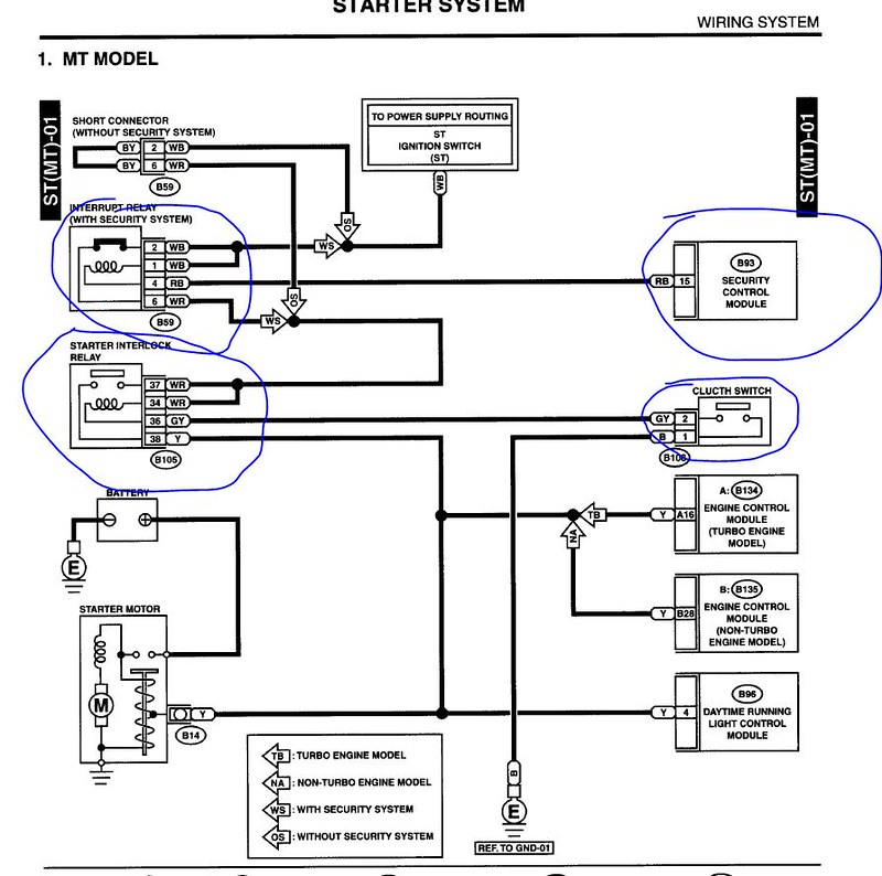
) I think one is the security crap and the other the interlock switch. Good to know we still need the relay, I planned on dumping it too.
    Frank
    818 chassis #181 powered by a '93 VW VR6 Turbo GT3582R
    Go-karted Aug 5, 2016 - Then May 19+21, 2017
    Tracked May 27/July 26, 2017
    Build time before being driveable on Sep 27, 2019: over 6000h
    Build Completed Winter 2021

  10. #50
    Harley818's Avatar
    Join Date
    Jan 2014
    Location
    Vancouver BC
    Posts
    788
    Post Thanks / Like
    Anyone know what this is for?
    I labelled it turbo, and the vacuum line is connected to the intake.
    photo 1.JPGphoto 2.JPG
    Harley
    Bought 2002 Donor Jan 2014
    First Start Jan 18, 2015
    First Drive Feb 14, 2015

  11. #51
    Senior Member Bob_n_Cincy's Avatar
    Join Date
    Sep 2012
    Location
    Cincinnati OH
    Posts
    3,904
    Post Thanks / Like
    Quote Originally Posted by Harley818 View Post
    Anyone know what this is for?
    I labelled it turbo, and the vacuum line is connected to the intake.
    photo 1.JPGphoto 2.JPG
    That is your waste gate solenoid.
    also know as an ebcs (electronic boost control solenoid)
    Bob
    818S #22 Candy Blue Frame, Front Gas Tank, 2.5L Turbo, Rear radiator, Shortened Transmission, Wookiee Compatible, Console mounted MR2 Shifter, Custom ECU panel, AWIC soon
    My Son Michael's Turbo ICE Build X22 http://thefactoryfiveforum.com/showt...rts-818S-Build
    My Electric Supercar Build X21 (on hold until winter) http://thefactoryfiveforum.com/showt...e-Build-Thread

  12. #52
    Senior Member STiPWRD's Avatar
    Join Date
    Jan 2014
    Location
    Leesburg, VA
    Posts
    1,624
    Post Thanks / Like
    Quote Originally Posted by Pearldrummer7 View Post
    Marked up my findings in bold. Similar to yours!
    I'm dieting my 2002 harness now and wanted to make sure I understood the consensus on the Integrated module. In order to delete it completely:

    On B280: Ground pin 4 (Black)
    On B281: Keep pin 16 (GrR) Lighting switch to B71
    On B281: Keep pin 18 (L) Lighting switch to B71
    On B281: Keep pin 19 (GR) Power to FB-20, Fuse
    Delete all other wires

    What do I do with the wires I keep? I'm deleting all the interior lighting but want to make sure I can illuminate the combination meter (dimmer not necessary). Would I need an on/off switch to ground on the two wires that run to B71? Can they be spliced to use the same on/off switch?

    Jaime also, mentioned wiring an on/off switch to GND on the Orange/White (on B281 pin 13) wire but this wire runs to the keyless entry module, which I already deleted. Do I need to worry about this OrW wire?

    Thanks for the help!

    Also, is anyone deleting the DRL system?

  13. #53
    Harley818's Avatar
    Join Date
    Jan 2014
    Location
    Vancouver BC
    Posts
    788
    Post Thanks / Like
    I've cut my IM, security, and Keyless entry as well and plan to connect to power somewhere to light the instrument panel. I'm keeping my DRL though.
    Harley
    Bought 2002 Donor Jan 2014
    First Start Jan 18, 2015
    First Drive Feb 14, 2015

  14. #54
    Senior Member Pearldrummer7's Avatar
    Join Date
    Feb 2014
    Location
    Asheville, NC
    Posts
    1,230
    Post Thanks / Like
    Replacing the crap Subaru provides in the harness with heatshrink crimp connectors:


    What's everyone else doing?

  15. #55
    Senior Member wleehendrick's Avatar
    Join Date
    Jul 2012
    Location
    Encinitas, CA
    Posts
    1,653
    Post Thanks / Like
    Blog Entries
    2
    Quote Originally Posted by Pearldrummer7 View Post
    Replacing the crap Subaru provides in the harness with heatshrink crimp connectors:
    Yeah, I was surprised to see how splices were made in the factory harness... but it seems to work and it's cheap.

    Quote Originally Posted by Pearldrummer7 View Post
    What's everyone else doing?
    I was planning to use the same, but I decided to out-source... I dropped my harness off with Brian (iWire) this weekend.

  16. #56
    Senior Member Bob_n_Cincy's Avatar
    Join Date
    Sep 2012
    Location
    Cincinnati OH
    Posts
    3,904
    Post Thanks / Like
    Quote Originally Posted by Pearldrummer7 View Post
    Replacing the crap Subaru provides in the harness with heatshrink crimp connectors:
    What's everyone else doing?
    I used post type terminal blocks with ring lugs on the wires. That way I could add wires as needed.
    Bob

    wire tags.jpg
    818S #22 Candy Blue Frame, Front Gas Tank, 2.5L Turbo, Rear radiator, Shortened Transmission, Wookiee Compatible, Console mounted MR2 Shifter, Custom ECU panel, AWIC soon
    My Son Michael's Turbo ICE Build X22 http://thefactoryfiveforum.com/showt...rts-818S-Build
    My Electric Supercar Build X21 (on hold until winter) http://thefactoryfiveforum.com/showt...e-Build-Thread

  17. #57
    Harley818's Avatar
    Join Date
    Jan 2014
    Location
    Vancouver BC
    Posts
    788
    Post Thanks / Like
    If I'm lengthening or shortening lines, I'm splicing with Pico crimp connectors and their crimper, then protecting/insulating with heat shrink. This gives a good mechanical connection and insulation.
    The Subaru stuff I took apart all looked pretty clean and new given its 12 years old.
    Harley
    Bought 2002 Donor Jan 2014
    First Start Jan 18, 2015
    First Drive Feb 14, 2015

  18. #58
    Member
    Join Date
    Mar 2014
    Location
    Edwardsville, IL
    Posts
    99
    Post Thanks / Like
    I have a 2002 WRX. My car starts and the engine runs good, but I have a couple connectors that I need some help with. Pics below. Any help is greatly appreciated.

    IMG_0506.JPGIMG_0504.JPG

  19. #59
    Senior Member billjr212's Avatar
    Join Date
    Feb 2011
    Location
    Frankfort, IL
    Posts
    734
    Post Thanks / Like
    the black one is B82 - Diagnosis connector. I kept it - just in case.

    The white one looks like B250 - Flash memory connector - also need to keep if you intend to reflash your ECU ever.

Page 2 of 2 FirstFirst 12

Posting Permissions

  • You may not post new threads
  • You may not post replies
  • You may not post attachments
  • You may not edit your posts
  •  

Stewart Transport

Visit our community sponsor