Visit our community sponsor

Thanks:
0

Likes:
0
-
Administrator

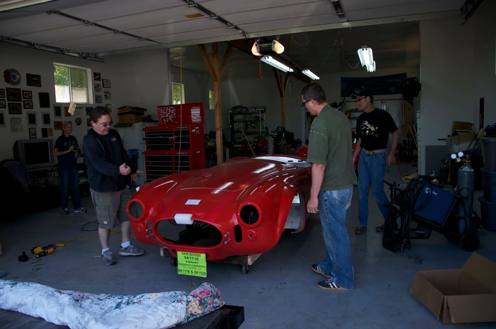
David's Mk4 Build Thread
This will be the thread documenting the build of my newly ordered Mk4 Roadster. It should be FULL of pictures with an extensive build log similar to my GTM Build hear: http://www.ffcars.com/forums/showthread.php?t=86384
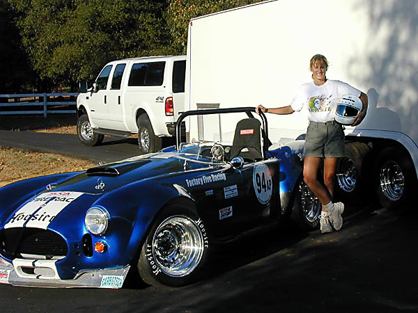
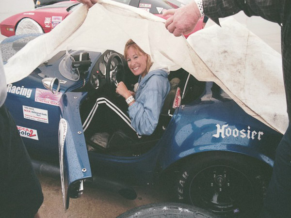
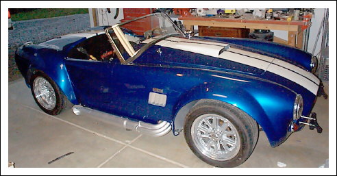
We made the decision to sell the Mistress(FFR 1046) which we have owned for 14 years and was built into a purpose built Autocross car. It was the first running/driving FFR in Ca! It went to a new home in Michigan and will be used for the purpose it was built. The Changes to the Mk4 put me over the edge from converting FFR1046 back to road duty so we decided to just starting fresh and let our old girl keep doing what she does best... go fast between the cones. 
We are very excited about this build... WOOT!
The details of the car will be:
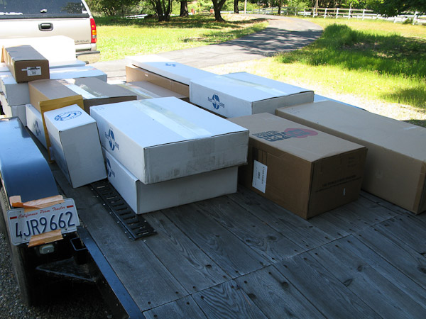
Complete Kit
IRS
Vintage Guages
Leather Seats
Bumpers and Overiders
427 Windsor
(need to figure out what tranny to run)
FFR 17 inch Halibrand style wheels
Paint by Ken Pike, Street Rod Painter!
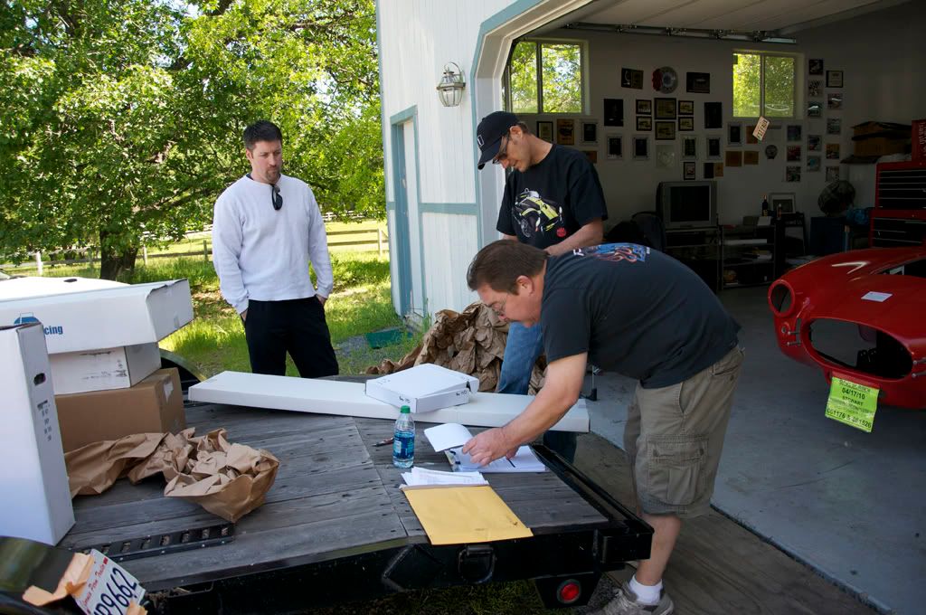
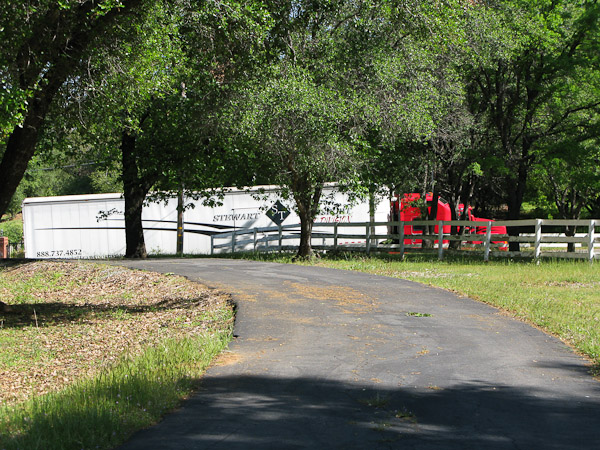
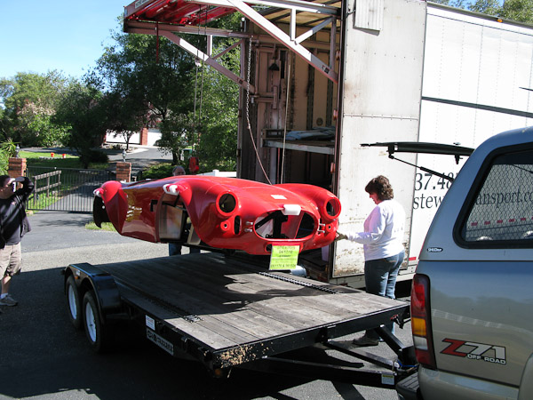
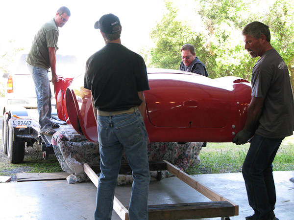
Transported by Stewart Transport
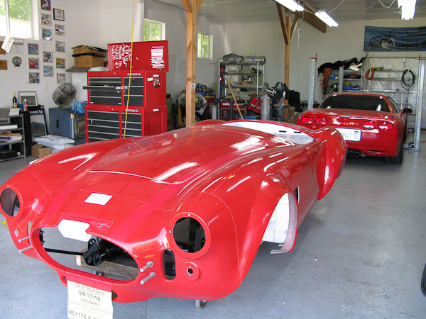
I'll get started on the thread once she arrives.. but just had to post...
David
-
Administrator
-
Administrator
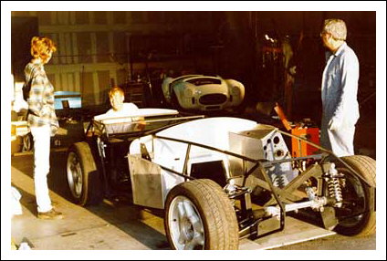
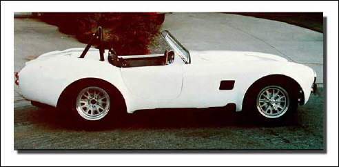
Firstly I just wanted to thank all the folks for the nice compliments regarding the Mistress and its evolution. As suggested earlier in the post, I thought it appropriate to take a few minutes and create a small tribute to the old car and reminisce about some of her history.
We purchased FFR1046 back in 1996 when Dave and Mark were doing a good part of the Assembly itself and even back then Mark Smith was actually welding some of the parts on the cars.
I had been looking for a Cobra replica for a few years, and ran across the FFR ad in kitcar mag. Once I saw the frame and found out it wasnt a fiberglass tub bolted to a flat frame, like pretty much all the replicas I had seen
and that it wasnt a cobra body put on a mustang frame, I was hooked.
This was back in 1996 and Mary and I had been married for a couple years and recently bought our first house. Previous to building the car, I done the normal car guy stuff
suspension upgrades, motor and clutch changes, mini restores etc. Funny thing is, the most powerful car I had to this point was probably 150 hp.
We had to scrape to even afford the $9999 kit. Sold some of the precious few shares of stock and re-financed a car. Probably not the smartest financial decision, but maybe one of the best for us! When we purchased the kit, it was the 2nd car shipped to CA.
We built the car on a shoe string using a donor pallet from Cypress in Oakland. the cutup stock mustang gauges and the provided FFR bezels. (Im sure very few on this board even remember thats the way you did gauges that long ago)
One thing I wasnt willing to compromise on was deep dish wheels out back, so I set about having a rear end narrowed. This was the first FFR with deep dish wheels.
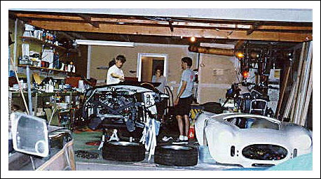
We had the kit and donor pallet delivered to a friends shop in Half Moon Bay and friends Steve, Steve, Kat and wife Mary spent a weekend and got the car to a rolling chassis with Motor and Trans installed!
-
Administrator
-
Administrator
-
Administrator
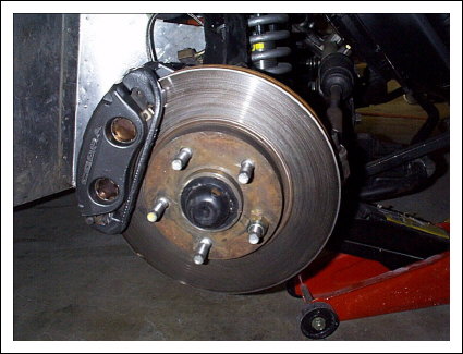
The mods begin.. in search of better brakes but clearance for 15 inch wheels. Fitting Cobra calipers on 11 inch rotors.
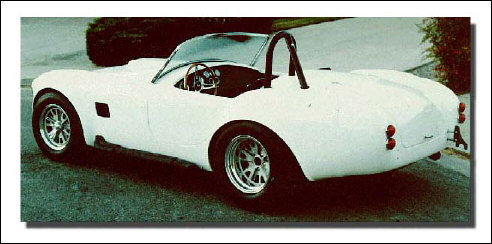
Finally painted after 2 years!
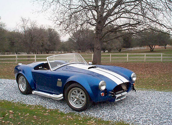
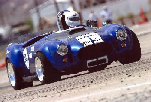
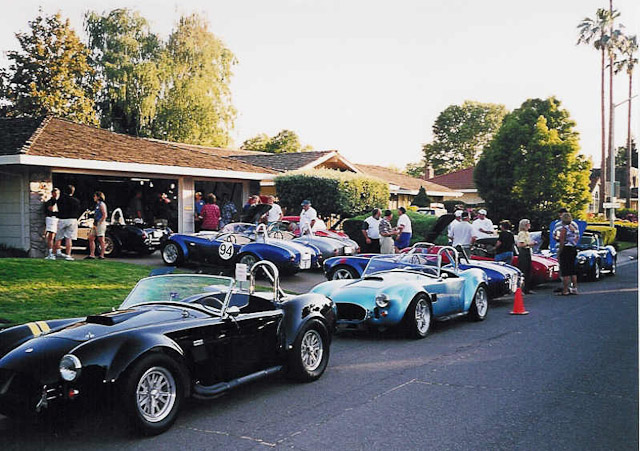
Mary and I loved to autocross and do track events, and we started running a few with the car. It was pretty funny.. pretty much everybody would come up and say.. these cars(cobra replicas) don’t do well on the track… for the most part, they were right! We wanted to prove them wrong!
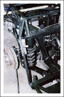
The car went through significant modifications over the next few years. IRS was added, 2nd retrofit after Wayne Presley, same as the swaybars using Speedway parts. I added a backbone to the car before the cobras had them, something that originated in the coupes.
-
Administrator
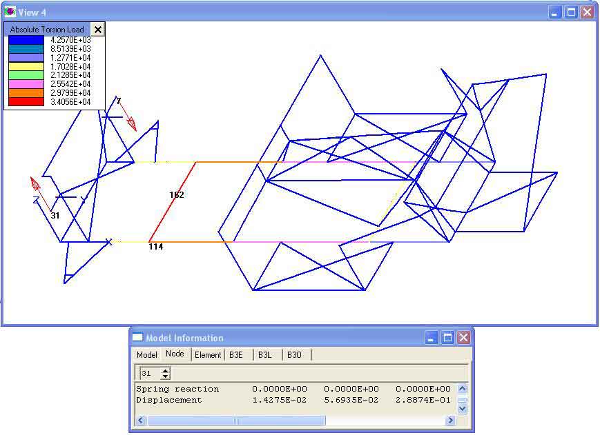
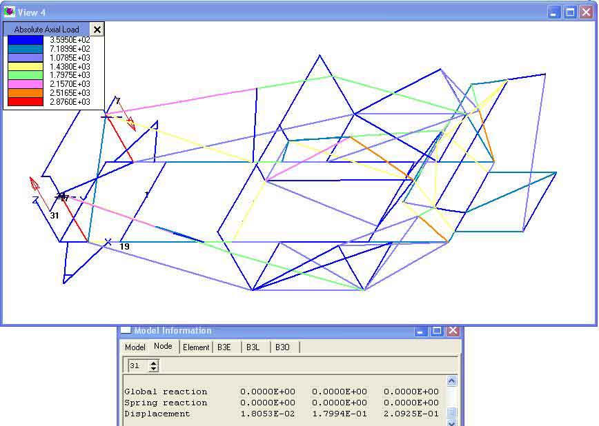
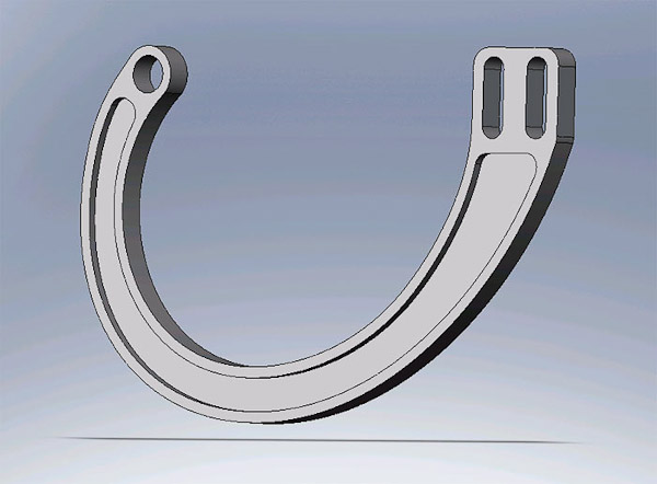
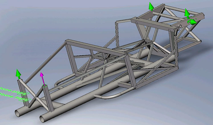
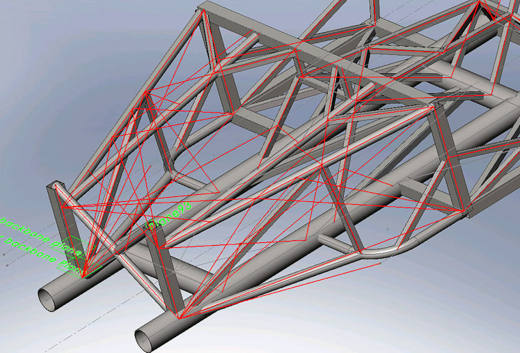
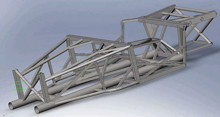
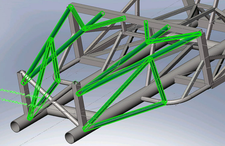
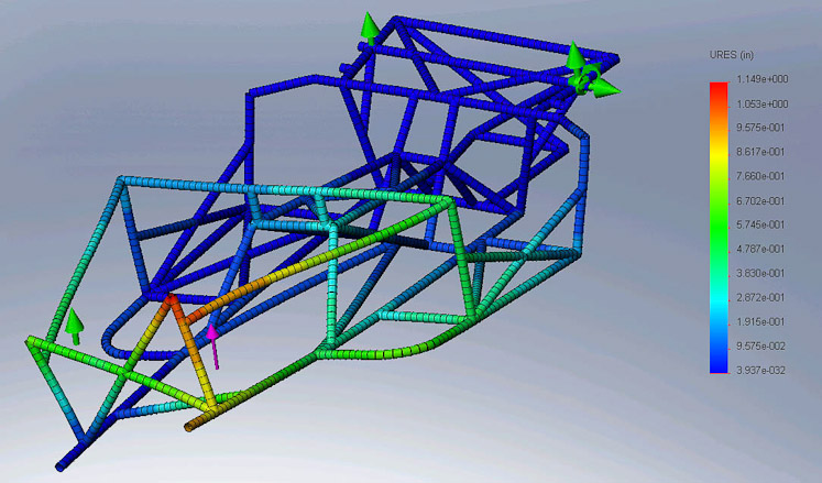
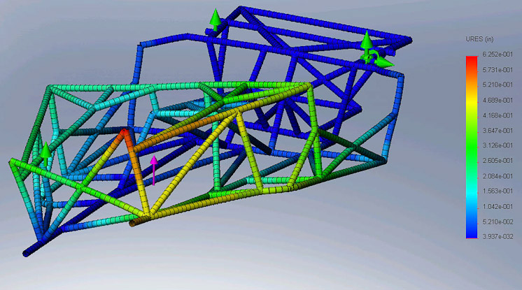
With the assistance of James Creasy, we used a shareware program called Grape to do FEA analysis on the FFR chassis and test mods to the frame in search of torsional rigidity.
A Vortech Blower was added as well as heads intake etc… to the tune of ~424rwhp.
http://www.youtube.com/watch?v=Fyu6o...eature=related
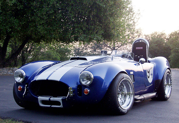
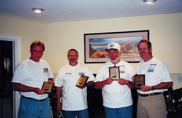
After about 4 years we developed the car to be pretty fast and became reasonable drivers as well as winning many Bay Area and Sac cup OSP championships.
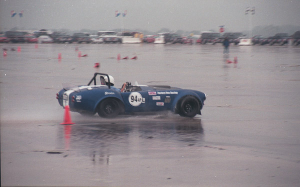
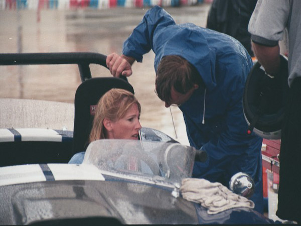
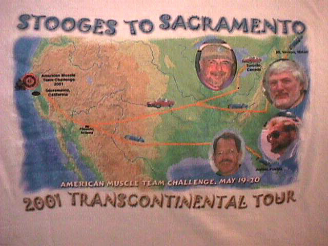
I got my first sabbatical at work and took the car to Run and Gun and we earned an overall Top Dog award. I remember getting on that oval for the first time and thinking to myself… why did I drive 2000 miles to do this.. It cold and slick and that’s a solid concrete wall .. Im nuts! A few videos from Run and Gun
http://www.youtube.com/watch?v=bc3nOyTWB8A
http://www.youtube.com/watch?v=TI6lk...eature=related
-
Administrator
-
Administrator
-
Hi Dave,
I've been following the build at the FFCars forum and its a great thread. It's great to see how you're figuring out how to make the Coyote work. Not to confuse matters: will you be updating both forums now?
John
-
Dave - Glad to see you've already made you way over to this forum with the MK4 build! I've been following it closely as you're providing significant inspiration for my planned Coyote-powered MK4
Last edited by jabm; 02-14-2011 at 11:00 AM.
-
Administrator
-
Administrator
-
Administrator
-
Administrator
-
Administrator
-
Administrator
-
Administrator
-
Administrator
-
Administrator
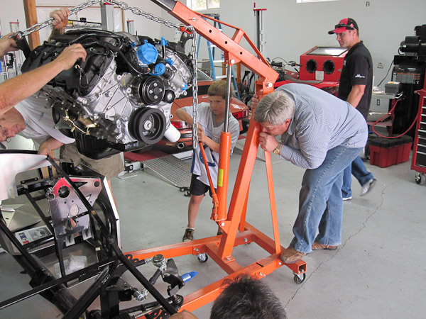
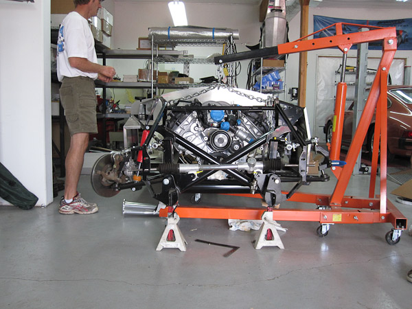
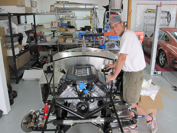
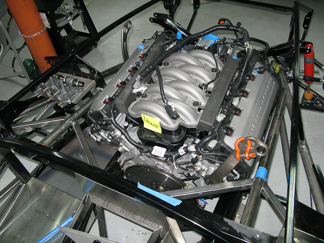
Motor mounts and headers are on the way and should be here tomorrow. Russ Thompson is coming up this weekend to pick up the shortblock he purchased from me and I think he is going to help me install the Coyote in the chassis so I can start mocking up the chassis mods. If anyone in the area is interested in coming up, let me know.
I put a deposit on a new 2005+ Tremec TR-3650 trans for a great price. This will allow for an OEM quality hydraulic clutch and shifter position is customizable.
I just spoke to these guys: http://coastdriveline.com/Contact.htm They said they can do a new driveshaft for a 2005+ trans to IRS with the slip yoke integrated into the driveshaft and balanced for $325. Ive heard this company is really good so if you are thinking of going with the 05+ trans this is another driveshaft option for you.(cross posted in the Modular forum)
If anyone needs a new driveshaft for an earlier car, I can sell mine. Brand new 31 spline 10.375 driveshaft from FFR. Shoot me a PM if interested.
David
-
Administrator
-
Administrator
-
Administrator

Originally Posted by
Adrian1281

Spoke to Bryan at FF5, was told that although they have the Coyote motor there and actually have been selling it to customers, he has not heard of them making any changes to the frame or aluminum panels. I was told to order the 4.6 kit from them and the motor should fit fine. Which is obviously confirmed by David's build...
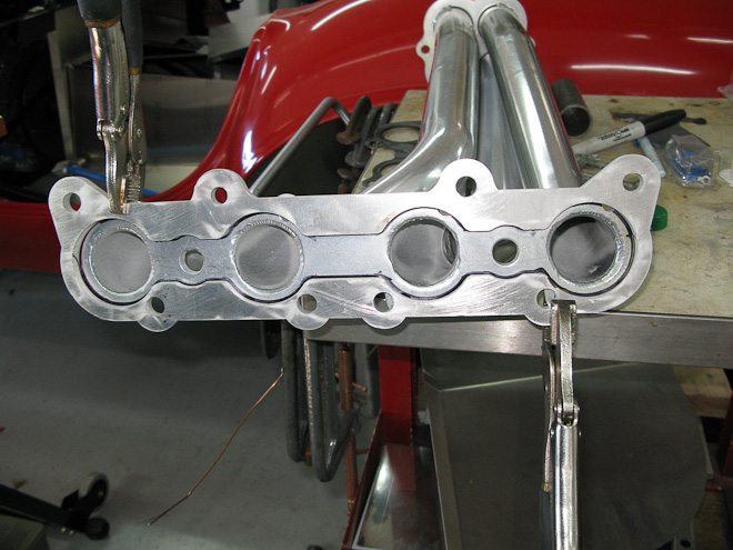
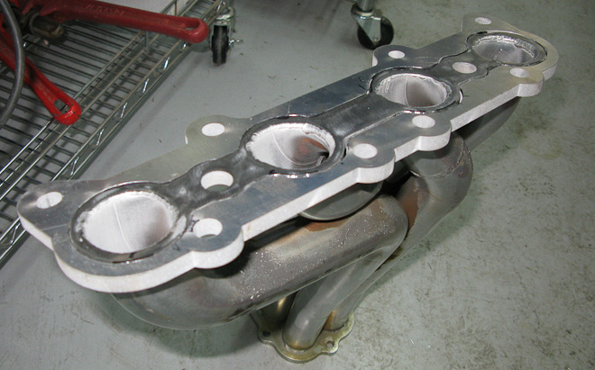
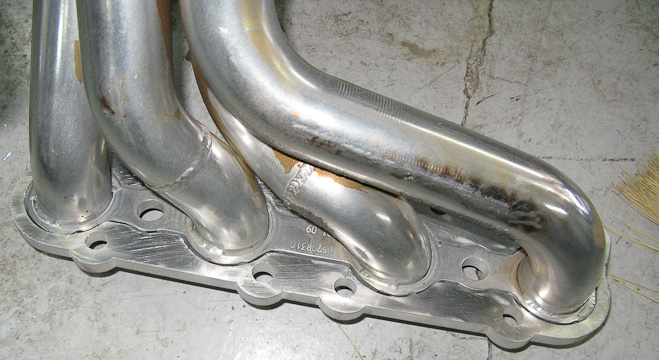
Only issue apparently are the headers will have to be modified or custom made I guess.
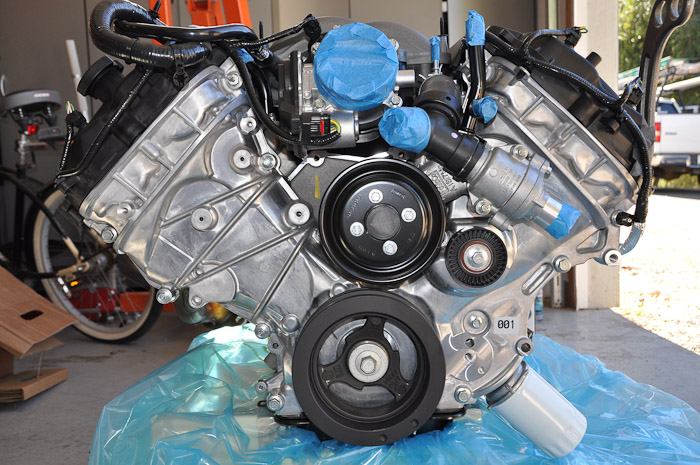
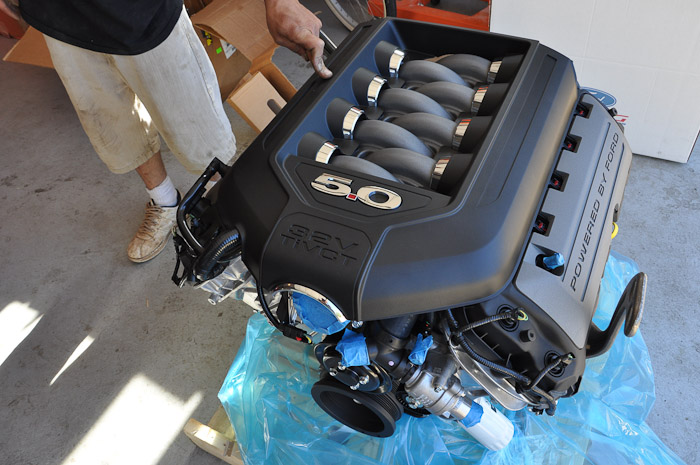
The areas that need to be worked through to put a 5.0 in the FFR Mk4
-Some sort of spacer for the stock 4.6 motor mounts.(this should be pretty easy to do) to raise the motor .5 inch.
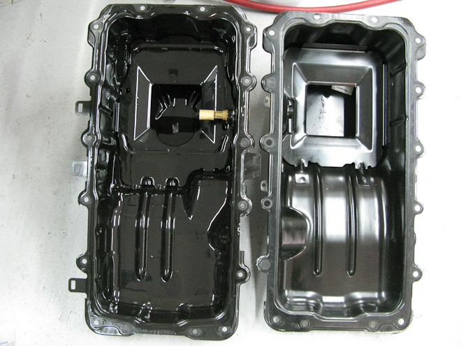
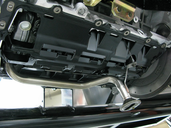
-A shallow Sump Oil Pan.(should be at least 1.5 inch shallower) I spoke to Canton and this is in the works with them. (Not sure if Champ pan Richard sells is working on this as well)
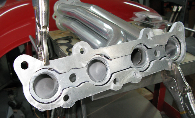
-Until FFR makes a compatible header, Modify the stock 4.6 headers. This should be pretty easy to do. Either cutting the flange off and welding on a new 5.0 flange, or making an adapter plate. The spacing and fit of the 4.6 headers seems pretty good, so this isnt a big deal if you have some fab skills or are willing to sub it out. Should be pretty easy and not any where near as complex as makiing new headers.
-Steering shaft may need to be tweaked very slightly. Its pretty close but raising the motor .5 inch might do it. Otherwise adding another joint would do it I think.
-Overall, its a great fit.... as far as I can see at this time, its not very complicated to adapt and it will only get easier as these parts are created for the specifc application.
David
-
Administrator
I thought the new 5.0L, like the 3V motor, was drive-by-wire and had to use it's own special pedal?
Correct. The 5.0 is throttle by wire and comes with a throttle pedal and harness as part of the engine control pack.
David
-
Administrator
Dave,
I might have missed it where you answered this, but what motor did you tell FF5 you were using when you ordered the kit?
In other words, are those the 4.6 specific motor mounts welded onto the frame?
You order a kit for the 4.6. The motor mounts on the frame are the same, but the motor mounts you get for the kit are different. There is also some different aluminum included for the drivers side footbox as Sergio pointed out earlier in the thread.
The headers you would want to get to modify for the 5.0 would be the standard 4.6 Headers. Same spacing but different flange. Still some work but definately doable.
David
-
Administrator
David -
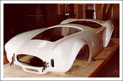
FF claims the MK4 body will require less body work to complete/paint.
Would you agree?
Thanks!
Im not a body man, but I think the body does look much better. I really like the hidden body fasteners, hinges, rounded cockpit etc.
Mostly I love the new shape very much!!
David
-
Administrator
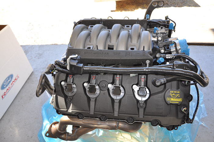
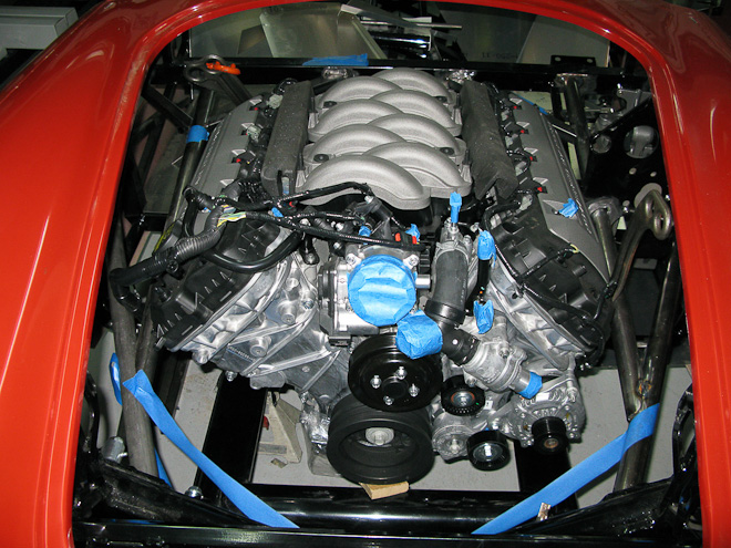
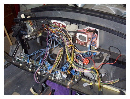
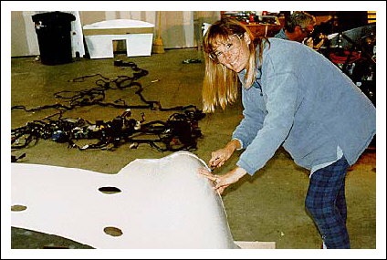
I got the custom engine harness, computer and TBW pedal.
I spent some time playing with the harness after work, laying it out to see possible routing solutions and found if I extend the passenger side cam position sensor wiring and a few others(a total of about 10 wires) I can easily get the computers plug back behind the firewall if I decide to put it there. I may consider putting it back up above the pass footbox as well. I'll know better once I see how the AC and heat fits in under the dash.
Im just glad I wont be forced to hack up the harness to much to get the clean look Im shooting for.
David
-
Administrator
-
Administrator
Will do Joe. My guess is it will be a month or two but will keep you and the rest of folks posted as I learn more.
How do you plan on mating the 5.0L engine management electronics with the rest of the car?
It looks like I'm jumping in the Coyote game as well, but i'm going to build the car first, and wait on a donor motor. Going to try and wait out a junkyard motor.
Depending, you may be well served to purchase the control pack engine intended for the motor for hotrod applications. There may be a whole host of issues to overcome that might save you a ton of time just getting the hotrod harness and ECU/TBW pedal.
Thats what I did and it appears there are just a handful of wires to hook up and splice into the chassis harness.
I'll try to cover that when I get there. Its going to be some time though as I will doing chassis mods first.
David
-
Administrator
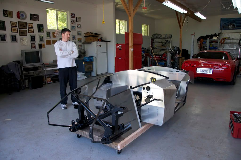
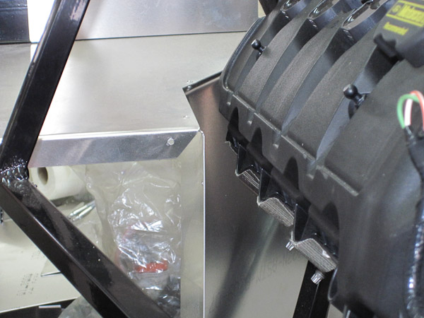
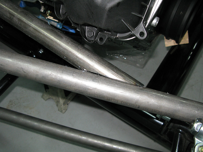
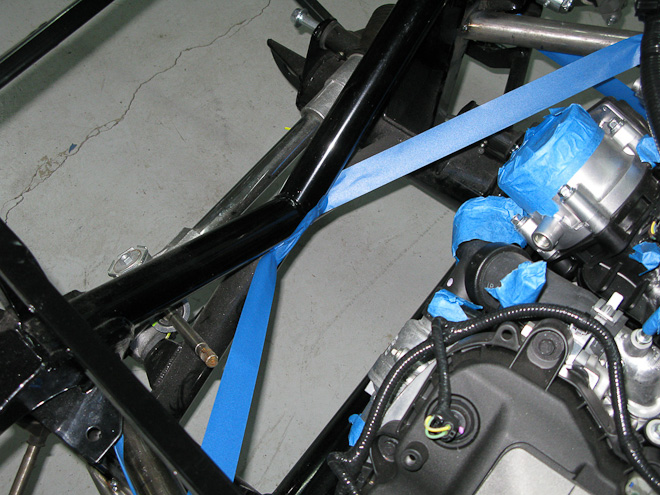
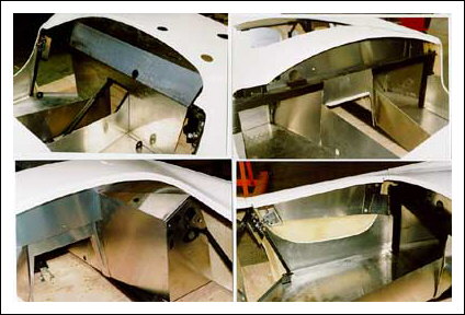
Spent a reasonable part of the weekend working on the chassis modifications and took the sawzall to the frame , officially starting the chassis mods I plan.(covered earlier in the thread)
I was able to fit three of the six 1.5 " primary chassis tubes and the fourth will be complete in about 30 minutes and all will be tac welded in place. It takes considerable time to hand fit these tubes as there are compound angles fitting round to flat, and round to round fitting with fish mouths.
Once I get them tacked to the chassis I'll take and post some photos and post them.
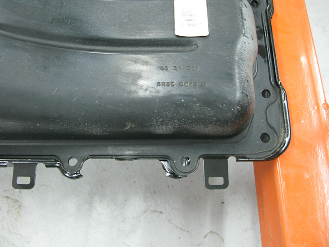
This week, I'll check with Canton and see if they received the oil pan I sent them and get an idea what they think the timeline will be.
David
-
Administrator
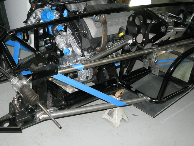
A quick update with pics to follow late this week.
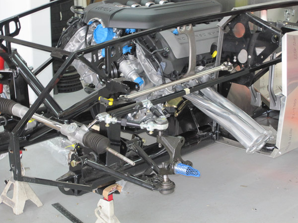
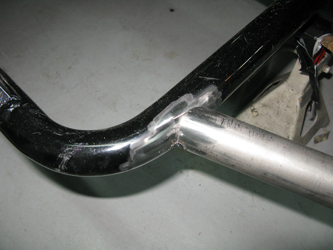
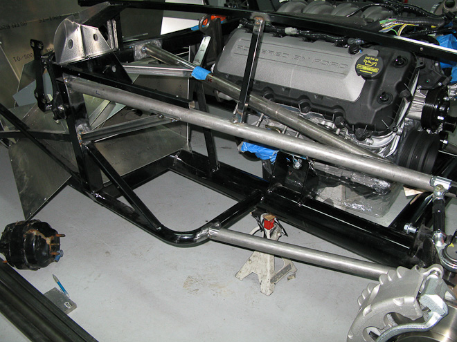
Over the last couple weekends, I finished fitting the main chassis tubes. Mike Downs, GTM builder came up to corner weight his GTM and check out the build. Once we finished up with his car he helped me hold the new tubes while I tacked them in place. Now that the 4 main perimeter tubes are in place I can fit the tubes that run next to the engine to see how much room I have to play with.
So far the only clearance issues I have are with the steering shaft between the rack and footbox and possibly a diagonal tube. It doesnt appear that I'll have trouble getting a power steering pump to work with AC on the passenger side if I decide to go that route. Should be plenty of clearance! The diagonal I may make removeable to help get the headers in and out without the having the body off
Other than that, I made it over to ASTGlenn's shop to pick up my transmission(it was shipped there). Man what a great shop they have. HUGE waterjet cutter which they have been making great looking 427 Comp dashes with. They have a Fadal Mill and every other tool you can imagine. Glenn and his son are just really cool people. I hung out for a couple hours and am stoked I was able to meet these guys... and they are only 10 minutes from my house! Thanks again Glenn for letting me come visit!
Hoping another good weekend or two and the chassis mods will be done and they on to making the brackets for AC and PS.
David
-
Administrator
-
Administrator
-
Administrator
-
Administrator
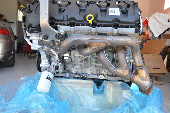
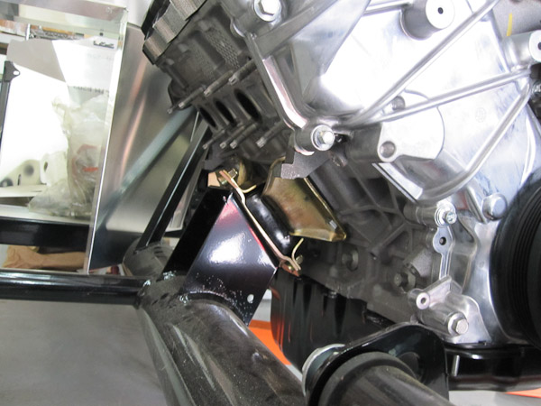
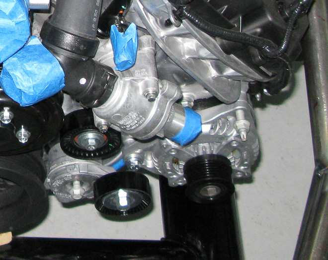
One more thing... I did get the Alternator kit for the motor and loosely installed it to check for clearance. Nice looking piece and fits tight up against the block and shouldn’t have any issues with header clearance.
David
-
Administrator
Very Nice Work!! I can't tell by the pictures but is the steering shaft going to interfere with the alternator? Also did you did decided to go manual steer over P/S or is the manual rack just for mock up??
Still plan on power steering. Thats just there for mock up. Need to find a good power rack still. If anyone has a good GT rack, they are not using, let me know.
The steering shaft will run right on top of the long tube that runs from the cowl forward. I will need to re-configure the linkage but Ive mapped it out and it should work well.
Much of the time doing these mods was spend on figuring that stuff out.
David
-
Administrator
David, I never gave the steering shaft/alternator situation a thought until I read it here. Is there any interference? Did you notice that the alternator fit is really sloppy? I think it will require a sleeve to take up the space in the block mount. Also, the belt that comes with the alternator "kit" is about 2 feet too long. As soon as I figure out the routing, I'll shop for the correct length belt.
No clearance issues with the steering shaft. I need to re-route due to the chassis mods.
Yeah I had the same intial problem with the alternator. Definately something missing. Sounds like a thing to bring up with Jesse? Did you happen to send him a note?
David
-
Administrator
Quick update.
Yep 05 Tremec 3650.
I got my SPCN(SB100) number first day the DMV was open this year. #128! Im just glad to get that behind me.
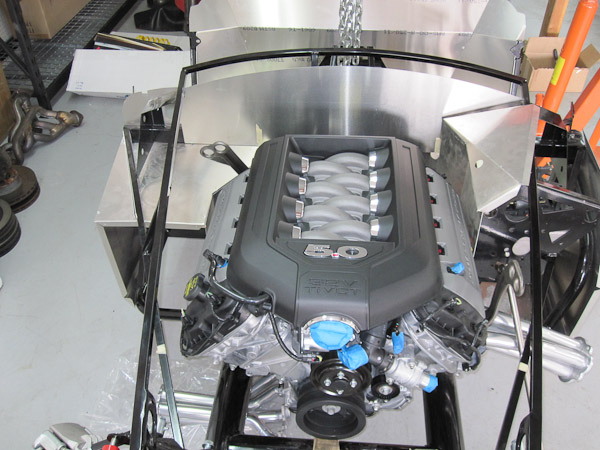
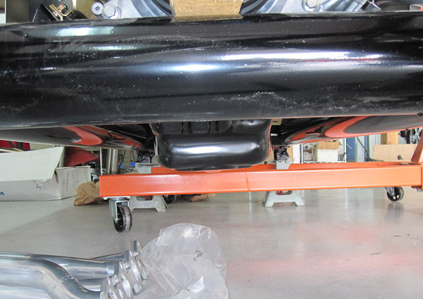
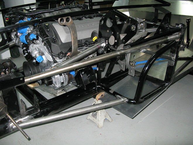
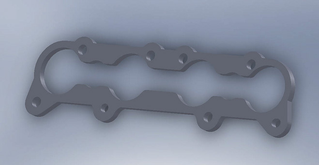
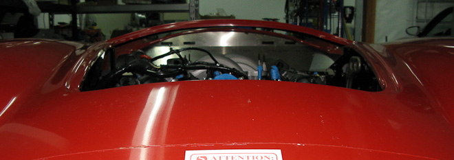
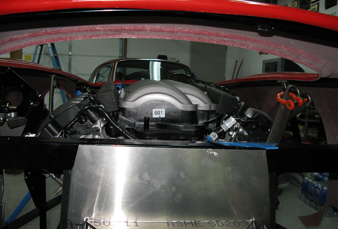
We mounted the body and found that the diagonal tubes Im planning to install wont interfere with the header install and removal with the body on. Also, it appears the headers will work fine as-is by welding on a new flange.
I do need a favor.... Can those with more recent Mk3 and Mk4's check and see how much clearance you have between your body and the side pipe? I will loose about .375" in header length bringing the headers closer to the body and would like to find out how much room I have to work with. Any help here would be greatly appreciated.
I need to work on getting some new flanges cut out of 3/8th steel. I may end up doing it on my mill but hoping a friend can help out 
The engine looks really good in there with the body on. I'll take some pics and post soon.
Sorry for the delay in updates. Work has been so busy lately that I just havent had much time/energy for the car stuff. It should lighten up some in the next few weeks so hope to make a bit quicker progress.
David
-
Administrator
-
Administrator
 Posting Permissions
- You may not post new threads
- You may not post replies
- You may not post attachments
- You may not edit your posts
-
Forum Rules

Visit our community sponsor


 Reply With Quote