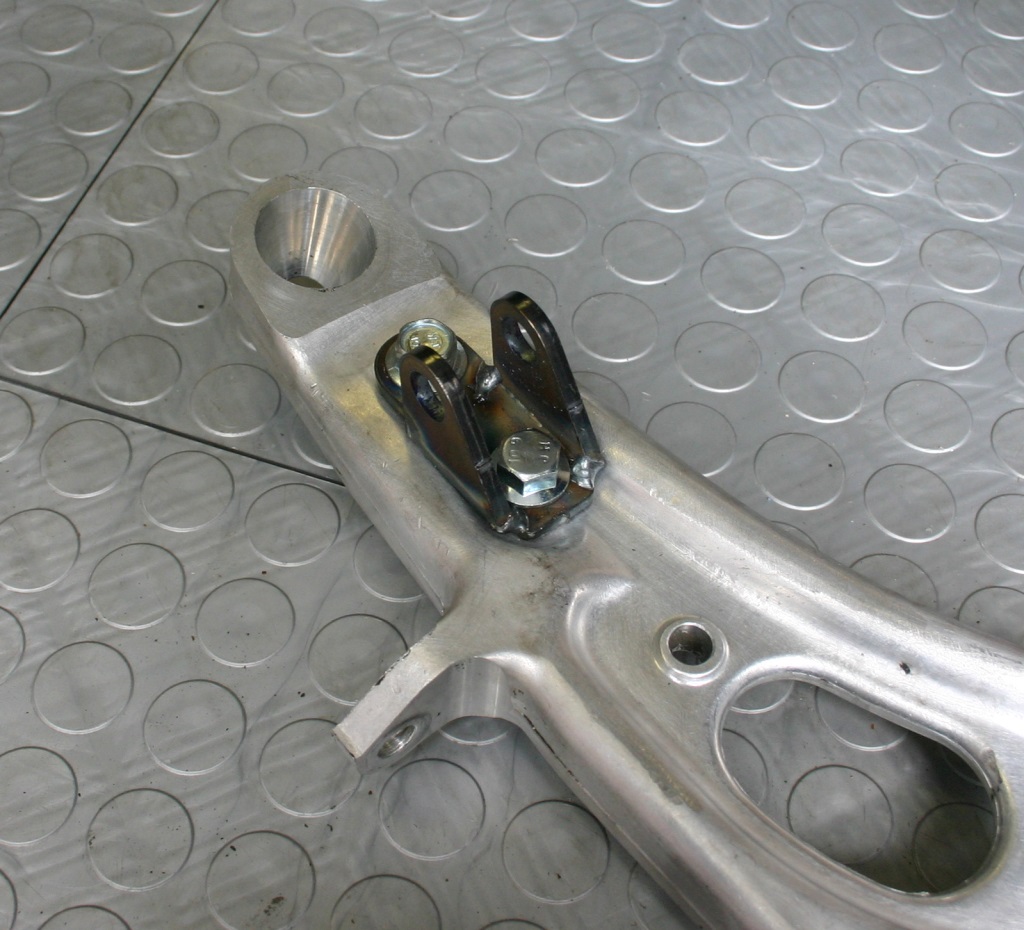
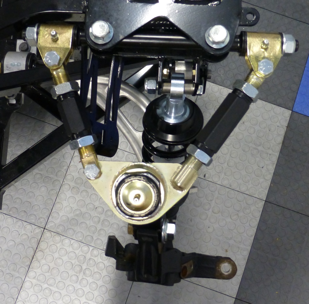
One thing that seems odd is the upper mount on the rear shocks. The manual specificly calls out to use a slightly smaller spacer in the front of the attachment point and the slightly larger spacer in the rear. However as you can see in the picture, with the smaller spaces the space is not filled up. I suspect that when I tighten the bolt it will just deform the bracket, but it seems odd.
I highlighted the gap with yellow lines.
Does anyone else have this problem?
I also started working on the axles. Since I am using the STI 114.5 spindles, I need to use the STI outer CVs. The causes a problem because the rear outer CVs from the STI are larger in spline count then the WRX ones. The axles provided by FFR will not work.
Here is a picture of the FFR axle, the STI front axle, and the STI rear axle:
[i
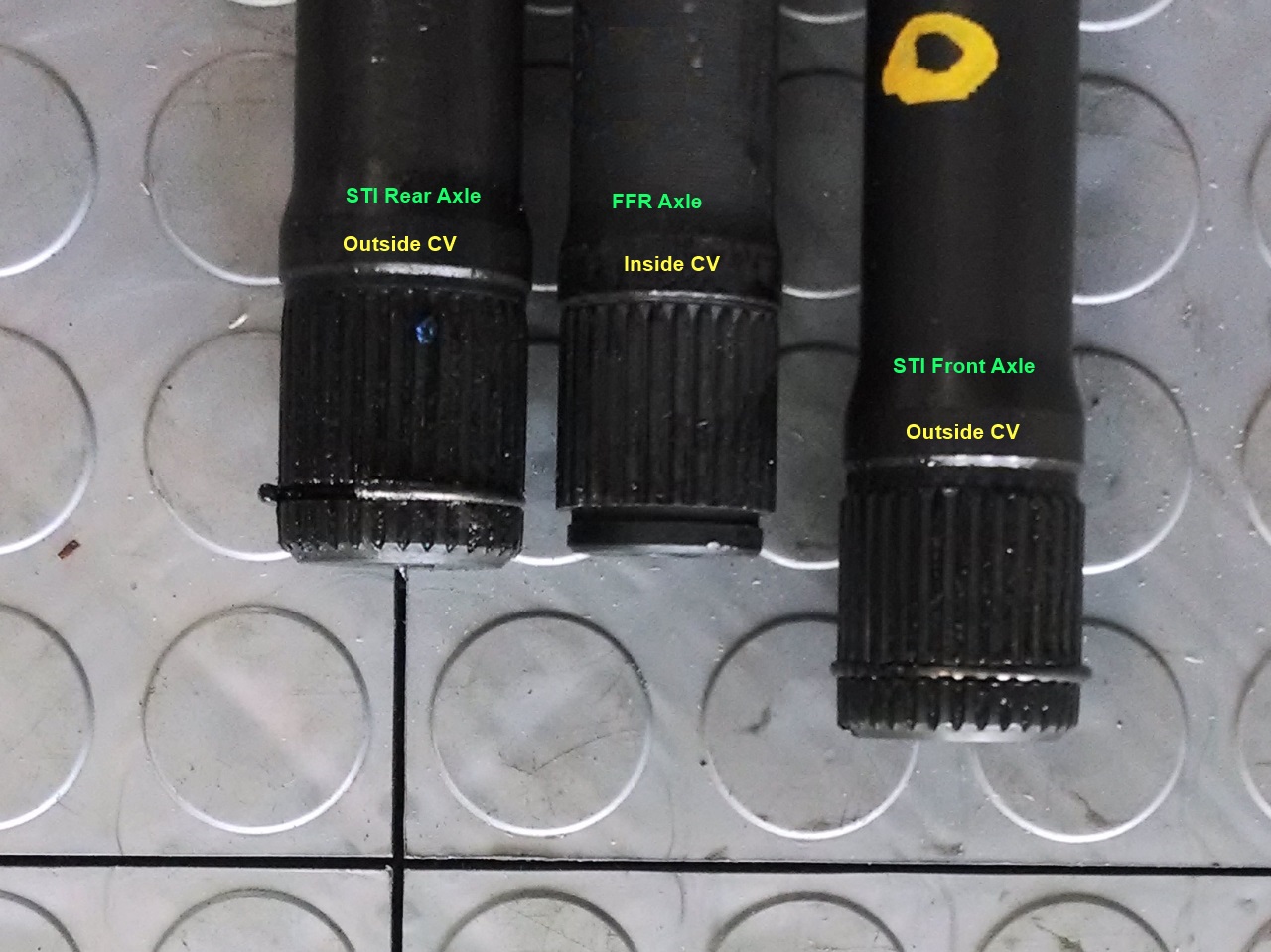
As you can see the STI rear axles are the perfect length (the same as the provided FFR one). Unfortunately the rear inner CV is larger spline count the the inner front CVs. Since I need to install front inner CVs to go into the transmission, those rear axles will not work. The STI front axles would work in terms of spline count, however the STI front axle is about an inch longer then the FFR axle.
Kurk818 mentioned that he is going to try using them, and it might work. There is about 2 inches of play in the inner CVs (which are the latitude sliding ones). If you start compressed 1 inch due to the axle being longer I am unsure if there is enough room left for full up to full down wheel extension. Once I get my transmission in, I'll assemble everything and see how it works.
I have one other complication that is different from Kurk818. I am using an Andrewtech 5-speed, and 5-speeds usually have stub outputs (held in by a lock ring). I would like to use the 06 STI front inner CVs that I have which are stubs as well. I talked to Sam an Andrewtech and he said he thought it was possible to convert the 5-speed to use axle stubs. On the 04 STI 6 speeds it is pretty easy as there are seals and rings for both designs. Hopefully this will work out.
If by change I can't get the 5-speed to work with the STI stubs, I will have to get a set of WRX inner front stubs (well stubless stubs) and have a custom axle made that can do the STI outers with WRX inners.
Either way I'll get it working, but it would be great to have everything all set to use either a 5 speed or a 6 speed without changing axles,
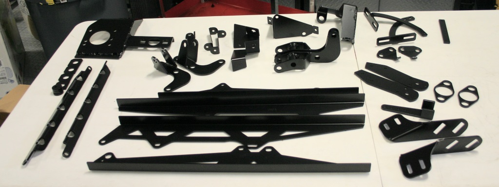
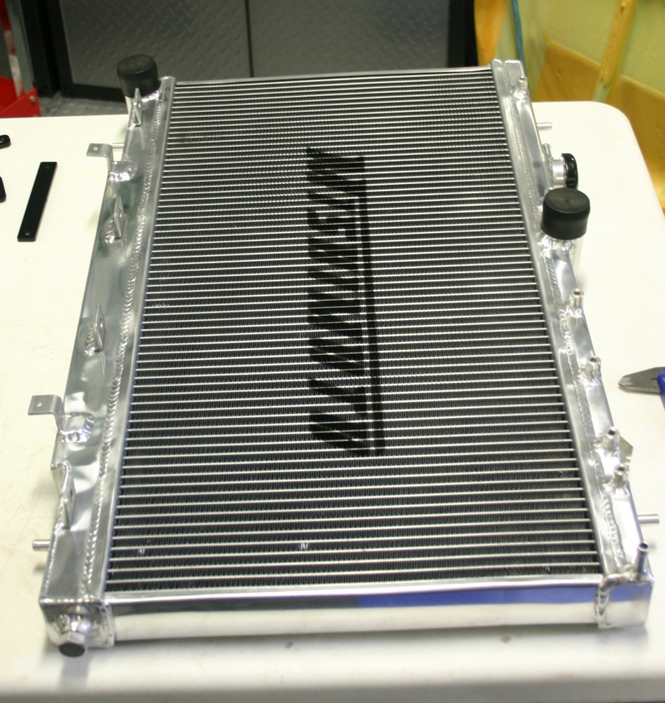
Oh I also ordered a bunch of goodies from VCP today (AWIC, arms, ktuned shifter), Rori ( Ktuned brackets, rad brackets), ReplicaParts (Brake bracket), Boyds (Fuel Tank), Breeze (Coolant Tubes), Amazon ( Radiator, Nickel Copper Brake Lines ), and BrakeConnect (some 10mm x 1.0 fittings for 3/16s line.) Still need to get the good flare tool (Eastwood).. but stuff is on the way!
Jeff


 Thanks:
  Likes:


 Reply With Quote


 .
.


") . The firewall can be done a number of ways. I cut the 90° and 75° bends out and welded them together. Or you can cut the 3" section between the 90 and 75 to 1/2" on each side, overlap the two 1/2" sections and bolt them together (or weld).
. The firewall can be done a number of ways. I cut the 90° and 75° bends out and welded them together. Or you can cut the 3" section between the 90 and 75 to 1/2" on each side, overlap the two 1/2" sections and bolt them together (or weld).
