The second owner had switched the car over to a ViPEC stand alone ECU, replaced the doors, hood, and trunk with carbon fiber parts, and left the engine and transmission just as Jeff Perrin had built it The car only has 20,000 miles on it, with about 5k on the EZ30R. It makes about 600whp and 560 lb-ft of torque with the 4088 at a medium boost level as Jeff Perrin tuned it.

Here is the engine removed from the car on an engine stand. It currently has a twin scroll manifold with a GT35R, although I plan on going back to the GT4088 that Jeff had originally used.

 818 Goal:
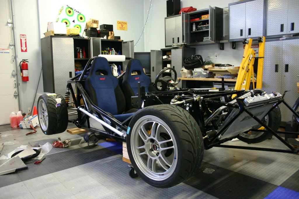
I’m building an 818S, so this will be registered street car. My 02 WRX is my dedicated track car, I have an 08 STI with ~500whp that is my daily driver (especially in the rain), a twin-turbo 2006 GTO that is my' I have no traction' car, and a new 2014 GT-R that is my 10 sec street car. So…. For the 818 I am going to try and build the fastest 0-60 and ¼ mile acceleration 818S. Given the power output of the EZ30R (~600whp), and the weight of the 818 (1950 lbs with the heavier H6), I think a high 9 second time is reasonable with the right tires, and perhaps mid 10s on a street friendly tire. So.. that is my goal.
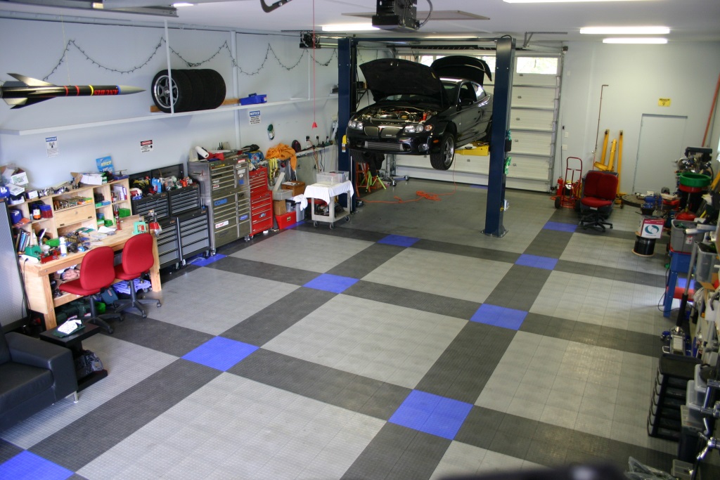
I’m doing the build in my shop at my house, which is helpful as I can do small amounts of work at a time and leave everything setup… and I have an 18 month old baby so time is already constrained! I have a lift in the shop, although that won’t really be needed for this build.
I’ll be tearing down the rest of the 06 STI in prep for the arrival of the kit. I would like to have ABS working, so I plan on moving those pieces over. I am using the STI drivetrain including the hubs and brakes as well as the 6-speed transmission. I have a spare 6-speed that I am going to have custom gears made for once I get everything moving along. To get a decent ¼ mile time I need taller gears. Oh.. and a RaceLogic Traction Control setup (as per
http://thefactoryfiveforum.com/showt...ol-for-the-818)


 Thanks:
  Likes:


 Reply With Quote


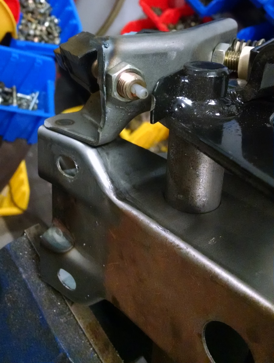
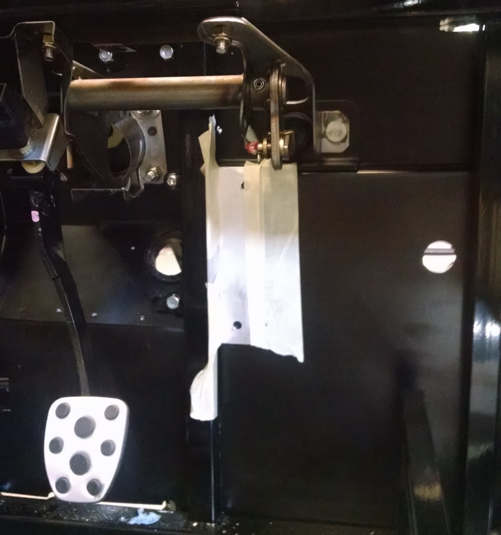
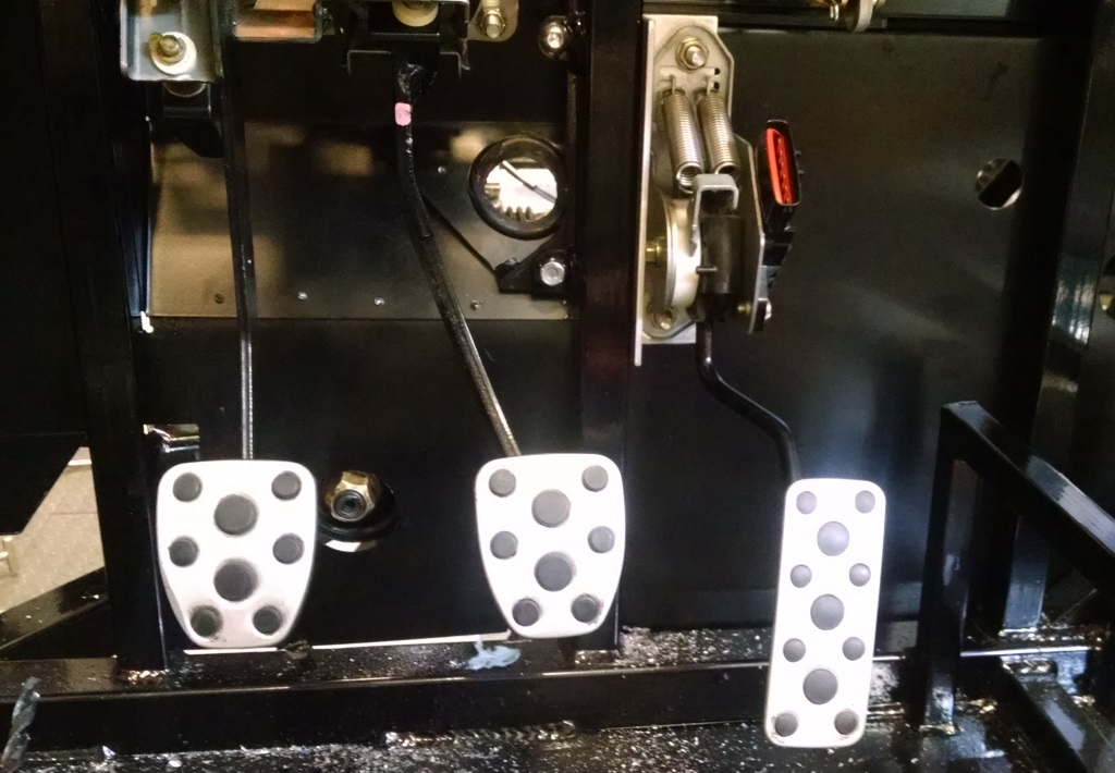


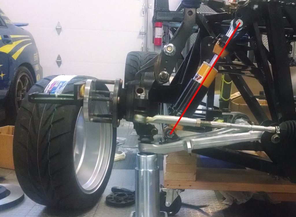
 There goes some more custom brackets for me.
