BluePrint Engines

Visit our community sponsor

Thanks Thanks:  0
Likes Likes:  0
Page 1 of 2 12 LastLast
Results 1 to 40 of 43

Thread: Upgrade - LCA SN95 Spindles 99 PBR Brakes & New Shocks

  1. #1
    Senior Member HookedonFord's Avatar
    Join Date
    Feb 2011
    Location
    Panhandle, FL
    Posts
    143
    Post Thanks / Like

    Upgrade - LCA SN95 Spindles 99 PBR Brakes & New Shocks

    I have been collecting parts to upgrade to 1995 SN95 spindles/hubs with 1999 PBR dual piston brakes and tubular lower control arms. I followed Eddie's upgrade post SAI Mod and Brake Upgrade - great post, well documented (Thanks Eddie!) Now I have a buddy, Jason, in Afghanistan that is a huge Car Nut, I told him I would send him pictures of car work to keep him connected to his favorite hobby and thought I would try to help some of the other forum members that might be upgrading Fox setups with this post.

    WARNING! Incorrect assembly and maintenance of these parts can cause serious injury or death.


    Last edited by HookedonFord; 07-29-2014 at 08:15 AM.

  2. #2
    Senior Member HookedonFord's Avatar
    Join Date
    Feb 2011
    Location
    Panhandle, FL
    Posts
    143
    Post Thanks / Like

    Post The setup and parts


    Existing Setup MKII:
    Brakes calipers - 1990 Mustang GT with Steeda sleeves
    Rotors - Lincoln 5 Lug Rotors
    Pads - Performance Friction 0431.10
    Lower Control Arms - 1990 Mustang GT
    Spindle Adapter Bracket – 2-hole FFR for Fox
    Spindles - 1990 Mustang GT
    Upper Control Arms – Factory Five “gold” (late MK2, early MKIII)
    Wheels – Team III, 7” x 15” fits Fox brakes
    Brake lines - Russell Stainless Brake line kit 693010
    Bleeders - Speed Bleeder 639540
    Master Cylinder - 1993 Cobra
    Shocks - FFR provided Pro Shocks

    UPDATED 7/29/14
    New setup:
    Brake Calipers - 1999 Mustang GT PBR with mounts C466 and C467
    (2) Rotors - 1999 Mustang Rotors 11" Advanced auto part# YH141911
    Pads - Hawk HPP HB274N.610
    Lower Control Arms - TriStates tubular lower control arms, modified
    Spindle Adapter Bracket – newer 4-hole FFR for Fox/SN95 from forum
    Spindles - 1995 Mustang Spindles, already clearanced for PBR calipers
    Upper Control Arms – Factory Five “gold” (late MK2, early MKIII)
    Wheels – Team III, 8” x 15” 5 1/4" backset checked for PBR clearance (thanks Compunetexpress for the front wheels)
    Brake lines - Stifflers Stainless Steel Brake Hose Kit, 1987-1993 Mustang FRONT with SN95 front calipers, BHK-MUST-1000FRTSSP $70 shipped
    Bleeders - Speed bleeders 639560 99-04 Mustang
    Master Cylinder - 1993 Cobra
    Shocks - Koni 30-1720
    Boots - Energy Suspension Upper and Lower control ball joints 5.13102G
    - Energy Suspension Tie rod boots 9.13101G
    Spindle spacer - Breeze Spacer Washer for SN-95 Spindle
    (2) Ford Front Hub Nuts, Ford part # F3LY-3B477-A, Breeze part #30201 $17.50ea + shipping
    Rack Pinion Boots (bellows) Car Quest part number 430-1049 (had a Moog K8465 number on it as well) $34.32 Local Car Quest for pair out the door
    (2) Ford Dust Caps, Ford part #F3DZ-1N135-A, Breeze part #30200 $11.85ea + shipping
    Breeze lower universal steering shaft kit for power rack (MKI and MKII only), part 70564 $129 + shipping
    Last edited by HookedonFord; 07-29-2014 at 08:27 AM.

  3. #3
    Senior Member HookedonFord's Avatar
    Join Date
    Feb 2011
    Location
    Panhandle, FL
    Posts
    143
    Post Thanks / Like
    Love these tool bags, easy to drag to each side. Picture with most important tool on top.

  4. #4
    Senior Member HookedonFord's Avatar
    Join Date
    Feb 2011
    Location
    Panhandle, FL
    Posts
    143
    Post Thanks / Like
    Removed the lower control arm, spindle/rotor, IFS bracket, shock, and upper control arm on both sides.
    Patched the under coating scrap from the tire on drivers side, I think it will blend in once it gets dirty.
    Last edited by HookedonFord; 06-01-2014 at 09:08 PM.

  5. #5
    Senior Member HookedonFord's Avatar
    Join Date
    Feb 2011
    Location
    Panhandle, FL
    Posts
    143
    Post Thanks / Like

    Capped lines

    I did not want to re-bleed the brake master cylinder, so I found a short metric bolt with nut of similar installed size for both lines and grabbed the crush washers off the existing caliper. I installed the bolt and nut with a crush washer on each side as I was removing the line.

  6. #6
    Senior Member HookedonFord's Avatar
    Join Date
    Feb 2011
    Location
    Panhandle, FL
    Posts
    143
    Post Thanks / Like

    Issues

    I found two issues so far, one minor and one major.

    The minor issue was a torn tie rod boot. I had already purchased a set of Energy suspension boots for Fox tie rods, part #9.13101G, since I planned to replace them.

    The major issue is a collapsed Pro Shock. I can can easily compress and extend it by hand. There are no signs of leakage. I had planned to upgrade the shocks later this year and have been asking Mark at Breeze some questions about the QA1's. I want to call Pro Shocks as well.


  7. #7
    Senior Member CraigS's Avatar
    Join Date
    Feb 2011
    Location
    Blacksburg, Va
    Posts
    4,729
    Post Thanks / Like
    I have a proshock you can have from my MkII. It has the small diameter springs so you would have to swap over your spring seats. To confirm, mine is 15 inches eye to eye and the threaded section of the body is about 1 3/4 inches OD. Email me at cstuard at comcast dot net. use proshock as the subject.
    FFR MkII, 408W, Tremec TKO 500, 2015 IRS, DA QA1s, Forte front bar, APE hardtop.

  8. #8
    Senior Member HookedonFord's Avatar
    Join Date
    Feb 2011
    Location
    Panhandle, FL
    Posts
    143
    Post Thanks / Like
    Craig,

    Thank you very much, but let me get a call in to Pro Shocks first and maybe a few other shock vendors.

    Jim

  9. #9
    Tool Baron frankeeski's Avatar
    Join Date
    Feb 2011
    Location
    "The I.E." SoCal
    Posts
    1,355
    Post Thanks / Like
    I believe the Proshocks are rebuild-able Jim.
    Frank
    __________________________
    Factory Five Racing MKIII Super Snake Replica. Cannonball Cobra Drop Trunk Box, Horn Button and other machined Do Dads.
    i.e.427 Chromed Full Width Roll Bar with integrated LED Third Brake Light.
    I will never forget My Buddy Paul.

  10. #10
    Senior Member HookedonFord's Avatar
    Join Date
    Feb 2011
    Location
    Panhandle, FL
    Posts
    143
    Post Thanks / Like
    Frank, they are rebuild-able and I am going to post some notes hopefully later tonight

  11. #11
    Senior Member HookedonFord's Avatar
    Join Date
    Feb 2011
    Location
    Panhandle, FL
    Posts
    143
    Post Thanks / Like

    Post

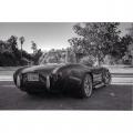
    Before I get back to updates I wanted to throw up a picture of Jason's car - 29 Blown Coupe (I will try to get a better picture)

    Last edited by HookedonFord; 06-03-2014 at 02:49 PM.

  12. #12
    Senior Member HookedonFord's Avatar
    Join Date
    Feb 2011
    Location
    Panhandle, FL
    Posts
    143
    Post Thanks / Like
    I jumped around a little and something I should have mentioned was that I tried taking parts off in reverse order of the build manual installation, but had to deviate some.

    I started with the tie rod ends, removed the cotter pins and and removed the nuts, then flipped them over (flat side up) and installed them about 1/4" before the tie rod end and nut were flush. Then I used the Big Hammer, a few good whacks and those separated easily. I left the tie rod nut on until I broke torque on the upper control arm ball joint and IFS bracket nut. I did not try to separate the upper ball joint from IFS bracket while installed.

    Removed the bottom nut and washer from donor shock mount that goes through the lower control arm.

    Loosened all the clevis nuts and bolts on the upper control arms, I left a arms bolted to the frame.

    Placed a jack under the lower control arms. Something I needed to reuse were the IFS bracket nuts and bolts, so I loosened and removed them. I then I hit the IFS bracket to separate it from from the spindle,rotor and lower control arm. At the point the upper control was free, except from the clevis bolts and nuts that were already loosened.

    With the jack in place I took out the lower control arm bolts and dropped the lower control arm, spindle, and rotor as an assembly.

    My main takeaway was to break torque on all the pieces you plan to remove because it easier to get leverage as an assembly than in individual pieces.

    Last edited by HookedonFord; 06-03-2014 at 07:05 PM.

  13. #13
    cobra Handler skullandbones's Avatar
    Join Date
    Jul 2011
    Location
    Superstition Mtn foothills 5 miles west of Gold Canyon AZ
    Posts
    2,686
    Post Thanks / Like
    Blog Entries
    19
    Were you going to post some pics of the before and after front of the car to show how the stance will change with the new spindles? That would be interesting to see. I noticed you had a rub on the F panel so that might be relieved a little with the extra width you get with the SN95 spindles. Nice upgrade! Also very good advice on the breaking the bolts as a unit. What a hassle when they are apart. Thanks, WEK.
    FFR MkIII 302 (ATK), EFI 75mm TB with custom box plenum chamber, 24# injectors, 4 tube BBK ceramic, cold air sys, alum flywheel, crane roller rockers, T5, Wilwood pedals, custom five link with Watt's link, 4 rotors, coil overs, power steering with Heidt valve, alum FFR rad, driver's crash bar mod, mini dead pedal mod, quick release steering wheel hub #6046

  14. #14
    Senior Member HookedonFord's Avatar
    Join Date
    Feb 2011
    Location
    Panhandle, FL
    Posts
    143
    Post Thanks / Like
    To separate the upper control arm (UCA) from the IFS I flipped the nut and installed nut about 1/4" from flush with ball joint stud. I mounted it in the vise and put a piece of wood under the UCA ball joint in case it slid. I then used one of the too many small plug sockets I have collected as a sacrificial guide and contacted it with the Big Hammer.

    Last edited by HookedonFord; 06-03-2014 at 06:55 PM.

  15. #15
    Senior Member HookedonFord's Avatar
    Join Date
    Feb 2011
    Location
    Panhandle, FL
    Posts
    143
    Post Thanks / Like
    SkullandBones,

    I did not consider getting pictures of the stance from the front before I started. Since I am using 1995 SN95 spindles I should not gain width there, but one of the main pieces I had to work out was changing wheels. I have had the spindles and core trade-in calipers since 2008, but when I did a mock up with my original 7" wide Team III wheels, the PBR calipers would not clear. Forum member (Compunetexpress) had a set of 15" x 8" Team III's that matched my rears and when I mocked them up, they cleared and backspacing is different, so there will be a width change with the wheels. I purchased new front and rear tires and mounted the fronts to the new 15" x 8" wheels before I started this and everything looked good. Weird thing about the F panel rub was it was only on one side. Now I wish I had some front pictures...

    Jim
    Last edited by HookedonFord; 06-03-2014 at 07:26 PM.

  16. #16
    Senior Member HookedonFord's Avatar
    Join Date
    Feb 2011
    Location
    Panhandle, FL
    Posts
    143
    Post Thanks / Like
    I called PRO shocks at 855-682-4404 and spoke to Mr. Brian Burns. He seemed very knowledgeable on shocks for the FFR Roadster. He mentioned the installed shocks were setup for 4 compress and 6 rebound. Since I had spoken/emailed with Mark at Breeze I wanted to know if they offered a SA and DA shock.

    Here are some of my notes:
    Rebuilding the current PRO shocks $65 each
    New PRO Shock ASB-546B (same shock) $179.99 each
    AFCO SA 3654-36Z Custom call in $279.99 each
    AFCO DA 3850-PTCZ $339.99 each
    Spring Racing Yellow in color 10" 450lb $65.99 each
    Spring Chrome 10" 450lb $44.99 each

    Also have a call in with Viking at 1-800-236-6001.

    The question I could not answer was the installed shock measurement because I have everything taken off, but we were able to work around it.

    Some pictures of the PRO shock / spring measurements commonly asked.

    Shock body 1 3/4"


    Spring length 10"


    Spring diammeter 3 1/2", more important was 2 1/2" ID


    Mounting Bolt diameter 1/2"

  17. #17
    Senior Member HookedonFord's Avatar
    Join Date
    Feb 2011
    Location
    Panhandle, FL
    Posts
    143
    Post Thanks / Like
    Craig,

    What is the proper way to get the extended shock length? Is it center hole to center hole?

    Jim

  18. #18
    cobra Handler skullandbones's Avatar
    Join Date
    Jul 2011
    Location
    Superstition Mtn foothills 5 miles west of Gold Canyon AZ
    Posts
    2,686
    Post Thanks / Like
    Blog Entries
    19
    You probably won't experience a lot of track difference but You should have a look at this site.

    http://www.maximummotorsports.com/te...4_spindle.aspx

    I used the later 96 - 04 spindles on mine because I moved the LCAs to the inside holes in the MKIII brackets so the added track was good. I calculated the width based on my Cobra R 9x17s which I was changing to and it came out just like I wanted it. The wheels and tires are tucked under the fender just perfectly.

    Regarding your F panel rub: have you considered centering the rack. I believe Breeze gives a tutorial on that. I haven't done it myself because my tires seem OK. I love suspension stuff so like to see threads like this. Keep up the good work!


    WEK.
    Last edited by skullandbones; 06-03-2014 at 10:10 PM.
    FFR MkIII 302 (ATK), EFI 75mm TB with custom box plenum chamber, 24# injectors, 4 tube BBK ceramic, cold air sys, alum flywheel, crane roller rockers, T5, Wilwood pedals, custom five link with Watt's link, 4 rotors, coil overs, power steering with Heidt valve, alum FFR rad, driver's crash bar mod, mini dead pedal mod, quick release steering wheel hub #6046

  19. #19
    Senior Member CraigS's Avatar
    Join Date
    Feb 2011
    Location
    Blacksburg, Va
    Posts
    4,729
    Post Thanks / Like
    That's how I measured, center to center.
    FFR MkII, 408W, Tremec TKO 500, 2015 IRS, DA QA1s, Forte front bar, APE hardtop.

  20. #20
    Senior Member FFRSpec72's Avatar
    Join Date
    Feb 2011
    Location
    Kirkland, WA
    Posts
    2,255
    Post Thanks / Like
    If you are going to upgrade the spindles, I would go with the FFR MkIV spindles, these can be adapted to earlier Mk models as we have done this on the Challenge Car series, these are far better than the SN95 and allow for more caster/camber and remove most of the bump steer (not all).
    Tony Nadalin
    2018 SOVREN Big Bore Champion
    2015 SCCA Oregon Region VP3 Champion
    2012 ICSCC ITE Class Champion
    FFR MkII Challenge Car, Spec Racer, Street Legal, SCCA, ICSCC and NASA Racing
    818R Build in progress

  21. #21
    Senior Member HookedonFord's Avatar
    Join Date
    Feb 2011
    Location
    Panhandle, FL
    Posts
    143
    Post Thanks / Like
    I received info back from Viking and they requested more, so here is the info and pics.

    Top loop distance is 1.42"
    Bottom loop distance is .83"
    Shock Extended length is approx. 15.75" center to center
    Shock Compressed length is approx. 10.5" center to center

    Top Loop measurement


    Bottom Loop measurment


    Shock Extended length


    Shock compressed length

  22. #22
    Senior Member HookedonFord's Avatar
    Join Date
    Feb 2011
    Location
    Panhandle, FL
    Posts
    143
    Post Thanks / Like
    FFRSpec72,

    I appreciate the MKIV spindle info, but I have 1995 SN95 spindles in hand ready to go. If some else is upgrading what would they have to do to use the MKIV spindles?

    Hooked
    Last edited by HookedonFord; 06-05-2014 at 09:48 AM.

  23. #23
    Senior Member HookedonFord's Avatar
    Join Date
    Feb 2011
    Location
    Panhandle, FL
    Posts
    143
    Post Thanks / Like
    I have been communicating with a Viking Performance Rep and the gentleman has been great to work with. My work load is slowing the communication down because I send info early in the morning and then scramble with the time difference in the afternoon to try follow up.

  24. #24
    Senior Member HookedonFord's Avatar
    Join Date
    Feb 2011
    Location
    Panhandle, FL
    Posts
    143
    Post Thanks / Like
    I have been getting some info from FFR on shocks, since the shock updates will be a couple a days or longer I moved back to the upper control arms.

    With the adjustment tubes and upper ball joint of the UCAs already removed I decided to inspect the SPC Pole Position cross shafts with pivoting ends (the ends pivoted well.) I removed the double snap rings and removed the ends, they looked good, only a few marks, cleaned them up with fine grit sand paper. One thing I did since reading Eddie's post was to grease the shafts with ends removed, watch out while doing it because it is like the BB gun in the Christmas Story "You will shoot your eye out." The old grease shot out nicely, I thought I took a picture, but it must have turned out blurry and I deleted it.

    The only casualty from cross shafts were the snap ring pliers, I broke a screw on one of the tips of the pliers. I needed a new pair and it seemed like Sears had a great deal on a pair less than $16 out the door and they looked just like the Channel Lock snap ring pliers. Craftsman Retaining Ring Pliers, Internal/External Item # 00947412000P Model # 47412

    It was a breeze finishing up the snap rings with the new pliers.


  25. #25
    Senior Member HookedonFord's Avatar
    Join Date
    Feb 2011
    Location
    Panhandle, FL
    Posts
    143
    Post Thanks / Like
    Decided to stick with PRO Shocks for a little while, but I did get some wrench time today and a bunch of prep work done.

    First thing, I started with was getting the frame tabs straightened from using the Mustang lower control arms by using a threaded rod spreader.


    After that I torqued the upper (MOOG K772) and lower (MOOG K719) ball joints to 125ft lbs. My understanding is that the MOOG K719 number is for the older style tubalar lower control arms. The MOOG K772 fits my late MKII uca's and may fit other uca's. I used the Blue Loctite following the MKIV build manual, because that was not in the my old manual. If I have any problems with ball joints loosening I plan to drill and safety wire. BTW, that chrysler ball joint socket is 1 7/8" with 3/4" drive, so I used a 3/4" to 1/2" adapter for the torquing purposes.


  26. #26
    Senior Member HookedonFord's Avatar
    Join Date
    Feb 2011
    Location
    Panhandle, FL
    Posts
    143
    Post Thanks / Like
    I have a question for some early adapters (old timers) of SN95 spindles on older style lca's.

    With the older style Chrysler lower ball joints there are shims/bushings that lift the spindle.


    Without the shim there is .22" of clearance between ball joint and spindle base.


    With the shim there is .40" of clearance between the ball joint and spindle base.


    My thoughts are you have to use the shim to provide room for the lower ball joint boot. When I did a dry fit, it did not look like I am going to need the spacer washer on top of the spindle below the nut like you would on the newer style lca's with a mustang ball joint. Looking for some input on this one.
    Last edited by HookedonFord; 06-16-2014 at 04:07 AM.

  27. #27
    Senior Member CraigS's Avatar
    Join Date
    Feb 2011
    Location
    Blacksburg, Va
    Posts
    4,729
    Post Thanks / Like
    No specific knowledge on this but...to me w/o the spacer it looks like the ball joint wouldn't be able to angle very much before it contacted the bottom of the spindle.
    FFR MkII, 408W, Tremec TKO 500, 2015 IRS, DA QA1s, Forte front bar, APE hardtop.

  28. #28
    Mark Dougherty's Avatar
    Join Date
    Feb 2011
    Location
    Hershey PA
    Posts
    722
    Post Thanks / Like
    defiantly use the shims
    the spacer on top is only to make sure the castle part of the castle nut engages the cotter pin
    The traveling Builder
    717-773-5624

  29. #29
    Senior Member HookedonFord's Avatar
    Join Date
    Feb 2011
    Location
    Panhandle, FL
    Posts
    143
    Post Thanks / Like
    Craig and Mark Thanks. Mark does that clearance between the ball joint and spindle base with shim in place look correct or do I need to add anything else? I was not worried about the top spacers, more so surprised that I probably would not need them.

  30. #30
    Senior Member HookedonFord's Avatar
    Join Date
    Feb 2011
    Location
    Panhandle, FL
    Posts
    143
    Post Thanks / Like

    Post LCA's, spindles, IFS Brackets installed

    Got a little time in this weekend.

    One thing I like about the MKIV build manual are the torque spec references, which for most part are the same, but I needed to add:


    IFS bracket to spindle bolts 140-200lbft.

    Lca's torqued parallel to ground at 105lbft. Installed the spindles with shims in place and Energy Suspension boots. I did not want to beat those IFS brackets on to spindles, so I used a mini spreader to install the IFS brackets making it very simple.

    Last edited by HookedonFord; 06-23-2014 at 09:49 AM.

  31. #31
    Senior Member HookedonFord's Avatar
    Join Date
    Feb 2011
    Location
    Panhandle, FL
    Posts
    143
    Post Thanks / Like

    Post Torque lower ball joint

    I planned to torque the IFS bracket bolts once I had the top and lower ball joints torqued. The bolts were hand tight, which helped to remove the lower bolt and pivot the the bracket out of the way to torque the the lower ball joint.


  32. #32
    Senior Member HookedonFord's Avatar
    Join Date
    Feb 2011
    Location
    Panhandle, FL
    Posts
    143
    Post Thanks / Like
    Spindles in place with upper and lower ball joints and IFS Brackets torqued.


  33. #33
    Senior Member CraigS's Avatar
    Join Date
    Feb 2011
    Location
    Blacksburg, Va
    Posts
    4,729
    Post Thanks / Like
    Don't get too concerned about the ball joint nut torque. Remember how hard it was to get the old ball joints out of the spindle? And you need to align the holes for the pin too so any torque spec used gets pretty much thrown away anyhow. You could torque to the minimum and then tighten further to align the holes.
    FFR MkII, 408W, Tremec TKO 500, 2015 IRS, DA QA1s, Forte front bar, APE hardtop.

  34. #34
    Senior Member HookedonFord's Avatar
    Join Date
    Feb 2011
    Location
    Panhandle, FL
    Posts
    143
    Post Thanks / Like
    Craig, kind of what I did. I went in the middle for torques giving me room to tighten the nuts to align the holes for cotter pins.

  35. #35
    Senior Member HookedonFord's Avatar
    Join Date
    Feb 2011
    Location
    Panhandle, FL
    Posts
    143
    Post Thanks / Like
    I received some correspondence from my buddy Jason, he mentioned he has limited time for internet access and the bandwidth is horrible for downloading pictures from the forum, which sucks.

    It was a family weekend, so no time on the car. I was able to do a little reading and forum research about steering rack offset bushings from reference provided by thefactoryfiveforum.com forum member skullandbones. Thanks for helping me spend money, I will try to help you when you post up an upgrade/project I decided to pickup a set of Breeze offset bushings while I have the tie rod ends off. As usual, called Mark at Breeze Automotive and had them in lightning speed and they look really good.


  36. #36
    Senior Member HookedonFord's Avatar
    Join Date
    Feb 2011
    Location
    Panhandle, FL
    Posts
    143
    Post Thanks / Like
    Starting working on the offset bushings and figured out how to center the rack, again nice pieces from Mark at Breeze Automotive.

    Ran into a few unexpected items. One rack and pinion boot (bellow) was torn. Looking at getting 2 each Moog K8439 - Moog Replacement Rack and Pinion Bellows.


    Then I thought I would change the rag joint, so I pulled the lower steering shaft. When I was inspecting it, I found cracks in the u-joint, difficult to see in the picture and hard to take a picture of.


    The steering shaft issue was very unexpected, but I am really glad to have found it. I am looking at a $175 Flaming River FR1509PLP low profile steering shaft, but I am not sure if it needs to painted. I noticed Breeze had a painted lower universal for $129. Looking for recommendations on these lower universal steering shafts and whether they need to be painted.
    Last edited by HookedonFord; 07-06-2014 at 12:53 PM.

  37. #37
    Senior Member HookedonFord's Avatar
    Join Date
    Feb 2011
    Location
    Panhandle, FL
    Posts
    143
    Post Thanks / Like

    Hubs and spindle shafts

    Since I needed to get some parts for the rack and pinion, I moved on and pulled the hubs to inspect them, since they had been in storage a while. The spindle shafts and hubs looked good. I was not digging the Dorman replacement gold spindle nut and I need to pick up some new dust caps. I will be calling the ford dealer tomorrow for:

    2 each, front hub dust cap, part # F3DZ-1N135-A
    2 each, hub nut, part #F3LY-3B477-A


    Last edited by HookedonFord; 07-06-2014 at 12:53 PM.

  38. #38
    cobra Handler skullandbones's Avatar
    Join Date
    Jul 2011
    Location
    Superstition Mtn foothills 5 miles west of Gold Canyon AZ
    Posts
    2,686
    Post Thanks / Like
    Blog Entries
    19
    You are smart to go with good quality hardware on those hubs. It seems very basic but still very important. I've had so many issues with trailer wheel bearings over the years, I don't want that problem on my car. Looking good! WEK.
    FFR MkIII 302 (ATK), EFI 75mm TB with custom box plenum chamber, 24# injectors, 4 tube BBK ceramic, cold air sys, alum flywheel, crane roller rockers, T5, Wilwood pedals, custom five link with Watt's link, 4 rotors, coil overs, power steering with Heidt valve, alum FFR rad, driver's crash bar mod, mini dead pedal mod, quick release steering wheel hub #6046

  39. #39
    Senior Member HookedonFord's Avatar
    Join Date
    Feb 2011
    Location
    Panhandle, FL
    Posts
    143
    Post Thanks / Like
    No wrench time this weekend, but more parts arrived.

    Rack Pinion Boots (bellows) Car Quest part number 430-1049
    Breeze lower universal steering shaft kit for power rack (MKI and MKII only), part 70564
    Ford Dust Caps, Breeze part #30200
    Ford Front Hub Nuts, Breeze part #30201
    Stifflers Stainless Steel Brake Hose Kit, 1987-1993 Mustang FRONT with SN95 front calipers, BHK-MUST-1000FRTSSP


  40. #40
    Senior Member HookedonFord's Avatar
    Join Date
    Feb 2011
    Location
    Panhandle, FL
    Posts
    143
    Post Thanks / Like
    I picked up a set of front and rear unused Koni shocks from the forum. They stopped by Viking Performance to be dynoed before I received them. Viking representative, Jake Neuman (952-469-4130) has been great to work with and they are looking at providing a DA shock in the near future.


Page 1 of 2 12 LastLast

Posting Permissions

  • You may not post new threads
  • You may not post replies
  • You may not post attachments
  • You may not edit your posts
  •  

Replica Parts

Visit our community sponsor