Boig Motorsports

Visit our community sponsor

Thanks Thanks:  0
Likes Likes:  0
Page 2 of 2 FirstFirst 12
Results 41 to 78 of 78

Thread: 3 Link, 4 Link, What Link???

  1. #41
    cobra Handler skullandbones's Avatar
    Join Date
    Jul 2011
    Location
    Superstition Mtn foothills 5 miles west of Gold Canyon AZ
    Posts
    2,686
    Post Thanks / Like
    Blog Entries
    19
    Check out the pics from post 38. That is where I am using the UCA flanges that I cut. They will mate to the bushings so it should be a perfect fit (with a little spreading). I also wanted to use them to reduce fab time and add a little dampening to the system. It will have less than the 4 bushing 4 link but still some. The chassis bracket will be mounted steel to steel. So I was planning on using the spherical rod ends. Don't want any binding in the system. I may do rod ends on at least one end of the lower control arms later. That would also give some alignment adjustment if needed. Thanks for the additional Afco source. I have been using Speedway but I will check around.

    Regarding the length of the upper third link: I do have concerns about that. However, the 4 link has been operational on my roadster and works fine. I don't experience any pinion angle issues. So I am thinking the similar length link should work. I will do my best to extend the length of that. I think I might fudge a little and get as much as 1.5 inches. That would put it at about 11.5 inches. Mike, what is the length of your upper link? Also, FFRs third link can't be that much longer than mine since there is only a limited space to work in. I know they cheat by putting it further aft but not that much. I guess the unknown after changing links will be to make sure pinion angle is OK. I will do pics and measurements lifted and at ride height as it is now to make sure I can get back to that setting when I make the change.

    I appreciate the critical thinking and input you guys give as it is, in my opinion, a real strength of this forum. It never hurts to have multiple pairs of eyes on the subject matter to get to a conclusion. I know it keeps me focused on the task at hand. Thanks again,

    WEK.
    FFR MkIII 302 (ATK), EFI 75mm TB with custom box plenum chamber, 24# injectors, 4 tube BBK ceramic, cold air sys, alum flywheel, crane roller rockers, T5, Wilwood pedals, custom five link with Watt's link, 4 rotors, coil overs, power steering with Heidt valve, alum FFR rad, driver's crash bar mod, mini dead pedal mod, quick release steering wheel hub #6046

  2. #42
    cobra Handler skullandbones's Avatar
    Join Date
    Jul 2011
    Location
    Superstition Mtn foothills 5 miles west of Gold Canyon AZ
    Posts
    2,686
    Post Thanks / Like
    Blog Entries
    19
    Got a chance to drive the roadster with the left UCA removed today. It is my first experience with the "Poor Man's 3 link" used on many of the Mustangs. I have not seen a lot of difference with the prior small changes with the watts link and the 4 link in combination but today was totally different. It works! The PM3L really works! I will continue driving the car like this for a while until I get my three link brackets and other link components. I was pretty skeptical about whether it would work but after experiencing it, it makes sense. Even though the upper link is on a severe angle, geometrically it works against the other control arms just fine. I tried it on regular driving and a little more severe curves and accelerations from a stand still to roll offs. I didn't hear any unusual noises or rubbing and no drive shaft related sounds. It was also OK as far as tires rub. What I noticed right off was a softer ride. I hope I can report some specific behaviors as I drive it for the next couple of weeks that will make more sense.

    To answer your question Mike, no I can not find any large parking lots that I feel safe enough to do donuts and such. If I do that around this area, the good ol' boys will have me eating asphalt and impounding my roadster. So I will have to find a place like a track. But I'm pretty happy that things have gone as they have so far. Next task is to complete the third link and try it out, too.

    Thanks,

    WEK.
    FFR MkIII 302 (ATK), EFI 75mm TB with custom box plenum chamber, 24# injectors, 4 tube BBK ceramic, cold air sys, alum flywheel, crane roller rockers, T5, Wilwood pedals, custom five link with Watt's link, 4 rotors, coil overs, power steering with Heidt valve, alum FFR rad, driver's crash bar mod, mini dead pedal mod, quick release steering wheel hub #6046

  3. #43
    cobra Handler skullandbones's Avatar
    Join Date
    Jul 2011
    Location
    Superstition Mtn foothills 5 miles west of Gold Canyon AZ
    Posts
    2,686
    Post Thanks / Like
    Blog Entries
    19
    A friend and I took a mountain road trip about 40 miles yesterday (early and the temp was down a bit). This was good because it allowed me some more time to try out the Poor Man's Three Link. It was very well behaved and rode very smoothly at speed and up and down and around the mountain curves and hills. I only have a few more days to get final impression of this setup. Never planned on keeping it this way but want to be able to say for sure one way or the other.

    Started fabbing the chassis bracket and although the other 4 link UCA was still in place, I was able to get a pretty good mockup of the bracket by using the left side as a template. I used the vise, cutoff saw and 50 lb anvil to shape the 3/16 inch angle bracket. When I receive the welding tabs for the 3 link and the other link parts I will remove the UCA (never to be installed again). It shouldn't take long to do the final fitting since I have done a lot already. Here are some pics of the bracket and the PM3L.

    Thanks,

    WEK.
    Attached Images Attached Images
    FFR MkIII 302 (ATK), EFI 75mm TB with custom box plenum chamber, 24# injectors, 4 tube BBK ceramic, cold air sys, alum flywheel, crane roller rockers, T5, Wilwood pedals, custom five link with Watt's link, 4 rotors, coil overs, power steering with Heidt valve, alum FFR rad, driver's crash bar mod, mini dead pedal mod, quick release steering wheel hub #6046

  4. #44
    cobra Handler skullandbones's Avatar
    Join Date
    Jul 2011
    Location
    Superstition Mtn foothills 5 miles west of Gold Canyon AZ
    Posts
    2,686
    Post Thanks / Like
    Blog Entries
    19
    One interesting thing I discovered about the third link today was a "rule of thumbs" or standard, I guess you could call it. It was a general article about the 3 link and it's strengths and weaknesses. It mentioned that the top link should be about 70% of the length of the lower links. So The FFR lower links are about 17.6 in and the upper link is about 9.25 in. My best estimate for the top link for my custom setup will be app 11.5 in. 70% of 17.6 would be about 12.3. I won't be able to do that but I think at about 65% is not bad at all. So hopefully this will improve the geometry a little. WEK.
    FFR MkIII 302 (ATK), EFI 75mm TB with custom box plenum chamber, 24# injectors, 4 tube BBK ceramic, cold air sys, alum flywheel, crane roller rockers, T5, Wilwood pedals, custom five link with Watt's link, 4 rotors, coil overs, power steering with Heidt valve, alum FFR rad, driver's crash bar mod, mini dead pedal mod, quick release steering wheel hub #6046

  5. #45
    cobra Handler skullandbones's Avatar
    Join Date
    Jul 2011
    Location
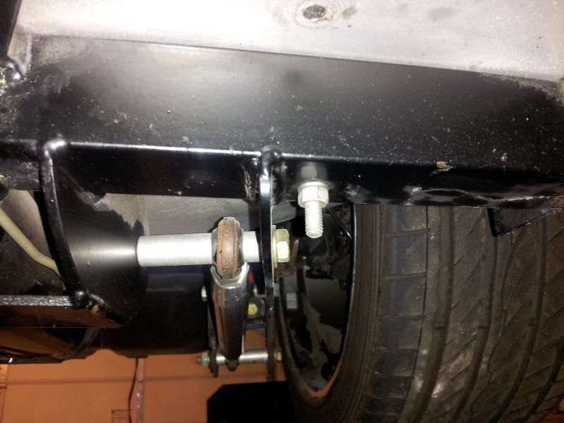
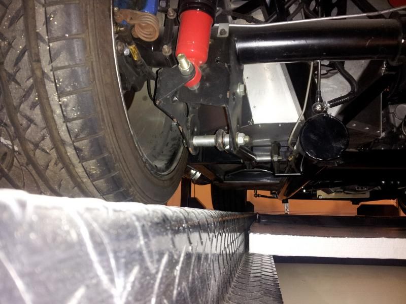
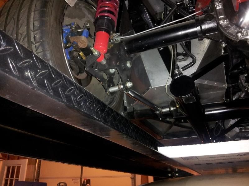
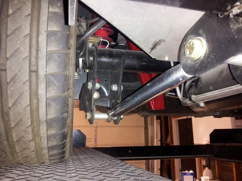
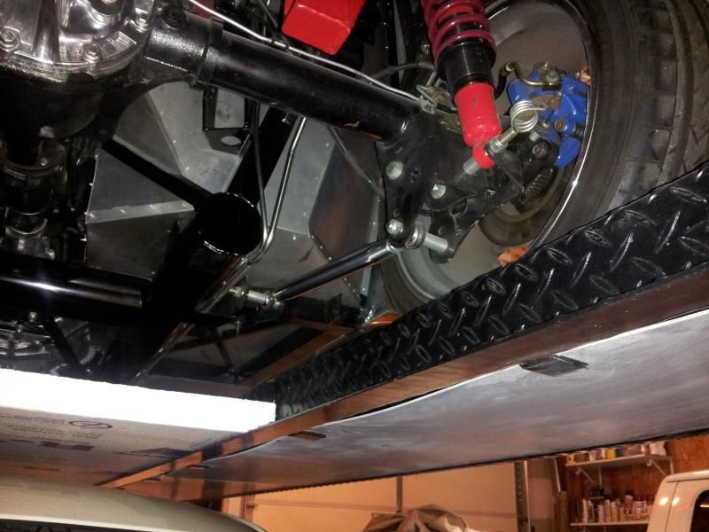
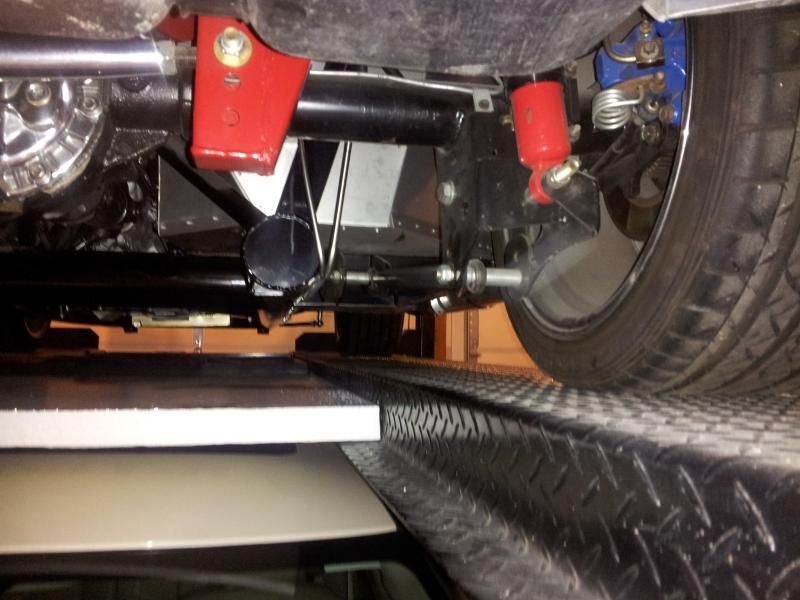
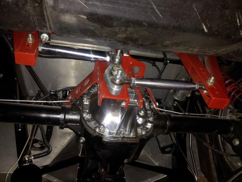
    Superstition Mtn foothills 5 miles west of Gold Canyon AZ
    Posts
    2,686
    Post Thanks / Like
    Blog Entries
    19

    Need to get pinion angle correct for new three link

    I disconnected the other UCA and started the modification of the UCA to attach to the three link bracket that sits on top of the diff. Here is where I have lost an important measurement. When I removed the UCA, the pinion must have drooped some. When I took the measurement for the length of the three link arm, it was quite a bit shorter than my initial measurement at initial mock up. So now it looks like I will have to rely on my initial measure to hook up the three link. My concern is to get the pinion angle right. I think I did an initial pinion angle measurement when I installed the 4 link (way back when). I'm sure it was within specs then. I was not concerned that it was something I had to bother to a great extent since I was using a basically un-adjustable suspension. I trusted FFR to get it right and it did work. With the FFR 3 link installation instructions, it says to use 2 degrees for a little more motion of the 3 link suspension. So my question is: especially if you have gone from a 4 link to a 3 link of some kind, what did you end up using for your new pinion angle?

    I don't want to blow up my drive shaft into a million pieces so I really could use some feedback. Also, how is the best way you have found to measure. I can't find a great way to tell if the diff is level. There is a small ledge running fore and aft along the pinion shaft. That is the flattest and only level looking place on there. I would like to get the trans tailshaft angle and pinion angle the same relative to the driveshaft. I've heard that is best.

    Thank you,

    WEK.
    FFR MkIII 302 (ATK), EFI 75mm TB with custom box plenum chamber, 24# injectors, 4 tube BBK ceramic, cold air sys, alum flywheel, crane roller rockers, T5, Wilwood pedals, custom five link with Watt's link, 4 rotors, coil overs, power steering with Heidt valve, alum FFR rad, driver's crash bar mod, mini dead pedal mod, quick release steering wheel hub #6046

  6. #46
    Not a waxer Jeff Kleiner's Avatar
    Join Date
    Feb 2011
    Location
    Bloomington, Indiana
    Posts
    8,090
    Post Thanks / Like
    When we speak of pinion angle we are referring to the pinion shaft relative to the transmission's output shaft. When determining pinion angle you can leave the driveshaft on the workbench, and in fact if you follow my method described below it will be easier if you do just that

    Don't get caught up or confused on any thoughts of horizontal. It doesn't have anything to do with the angle of the driveshaft or the engine and trans being level with the earth or chassis. Think of it this way; when looking at the car from the side if you were to project one line from the transmission output forward and another line from the pinion shaft forward with your pinion angle at zero they would be parallel. If you put any angle to the pinion the two lines are not parallel and would get farther apart as they go forward. If the pinion were to be angled UP (relative to the trans) it's line would be above the output line and get farther above it the farther forward it went. If it were angled DOWN it would be opposite---the pinion line would be below the transmission line and get farther below as it went forward. To set the pinion angle so that it is angled down below is what we're after . Clear as mud?

    My method for ease of measurement:
    Set ride height then put the car on jackstands so that the axle is loaded. Once again, we don't care if the frame is dead nuts level; we're only going to look at the difference between output shaft & pinion shaft. We know that the crankshaft and trans output shaft are parallel therefore the face of the damper/ crank pulley is perpendicular to the output. We also know that the pinion flange face is perpendicular to the pinion. See where I'm heading? I've always found that it is easier to get a good measurement with the magnetic angle finder by reading vertically on the crank pulley/ damper and pinion flange rather than trying to work with the horizontal shafts themselves. Once you can see the two angles you can then calculate the difference. Generally with these cars we want the pinion down somewhere in the vicinity of 2 degrees (once again, meaning the input is pointing down in relation to the transmission output shaft). Reason being is so that when the axle tries to rotate it's input upward under acceleration the pinion angle becomes less. This rotation is especially more pronounced on a 4 link car using the soft rubber bushings in OEM Mustang arms vs. a 4 link car with poly bushings or a 3 link with polys in the lowers and the solid upper link.

    Three link adjustment is easy; simply alter the length of the upper link. If your pinion angle is less than 2 degrees you would shorten the upper link to roll the nose of the diff downward or if it's greater than 2 degrees lengthen the upper link to bring the nose up.

    Hope that all makes sense and good luck!

    Jeff[

  7. #47
    cobra Handler skullandbones's Avatar
    Join Date
    Jul 2011
    Location
    Superstition Mtn foothills 5 miles west of Gold Canyon AZ
    Posts
    2,686
    Post Thanks / Like
    Blog Entries
    19
    Jeff,

    Just to make sure I'm understanding the terminology, when you say pinion flange do you mean the gusset like projection running fore and aft on both sides of the pinion shaft? That is what I was describing as the only level place on the diff I could find. I realize you don't need to be level though. So if I measure the pinion shaft angle by setting the angle guide on the ledge and the crank/pulley angle say on the crank shaft pulley and take the difference, it should be the same no matter if the car is level or not. Is that essentially correct? I hope so.

    Thank you as usual,

    WEK.
    FFR MkIII 302 (ATK), EFI 75mm TB with custom box plenum chamber, 24# injectors, 4 tube BBK ceramic, cold air sys, alum flywheel, crane roller rockers, T5, Wilwood pedals, custom five link with Watt's link, 4 rotors, coil overs, power steering with Heidt valve, alum FFR rad, driver's crash bar mod, mini dead pedal mod, quick release steering wheel hub #6046

  8. #48
    Tool Baron frankeeski's Avatar
    Join Date
    Feb 2011
    Location
    "The I.E." SoCal
    Posts
    1,356
    Post Thanks / Like
    Quote Originally Posted by skullandbones View Post
    Jeff,

    Just to make sure I'm understanding the terminology, when you say pinion flange do you mean the gusset like projection running fore and aft on both sides of the pinion shaft?

    Thank you as usual,

    WEK.
    No, the pinion flange is the flange that the drive-shaft bolts to on the front of the pinion gear snout.
    Frank
    __________________________
    Factory Five Racing MKIII Super Snake Replica. Cannonball Cobra Drop Trunk Box, Horn Button and other machined Do Dads.
    i.e.427 Chromed Full Width Roll Bar with integrated LED Third Brake Light.
    I will never forget My Buddy Paul.

  9. #49
    cobra Handler skullandbones's Avatar
    Join Date
    Jul 2011
    Location
    Superstition Mtn foothills 5 miles west of Gold Canyon AZ
    Posts
    2,686
    Post Thanks / Like
    Blog Entries
    19
    Oh yeah. That makes sense. Thanks, Frank! Also much more accurate surface to measure.

    Also, thanks, Jeff. I will try to get some measurements this evening when it cools off a little.

    WEK.
    FFR MkIII 302 (ATK), EFI 75mm TB with custom box plenum chamber, 24# injectors, 4 tube BBK ceramic, cold air sys, alum flywheel, crane roller rockers, T5, Wilwood pedals, custom five link with Watt's link, 4 rotors, coil overs, power steering with Heidt valve, alum FFR rad, driver's crash bar mod, mini dead pedal mod, quick release steering wheel hub #6046

  10. #50
    Not a waxer Jeff Kleiner's Avatar
    Join Date
    Feb 2011
    Location
    Bloomington, Indiana
    Posts
    8,090
    Post Thanks / Like
    Frank's got it! This is one of those things that many builders seem to fret over unnecessarily but is really simple to check and adjust. Good luck with the rest of your project!

    Jeff

  11. #51
    cobra Handler skullandbones's Avatar
    Join Date
    Jul 2011
    Location
    Superstition Mtn foothills 5 miles west of Gold Canyon AZ
    Posts
    2,686
    Post Thanks / Like
    Blog Entries
    19

    Custom 3 Link Completed

    I finally finished the components for the custom three link so I could clean them up and paint everything. So that's everything I needed to mount the third link on top of the pumpkin.

    This is a completely bolt in project. The bracket on the chassis uses the old 4 link pickup points and it mounts steel to steel with 4 1/2 inch bolts. The differential bracket mounts using the OEM bushing brackets with the same bolts that were used on the 4 link. To add some stiffness to this bracket, I added some steel strap supports that run down to the pinion housing. There is a very little flexing with the bushings but not much.

    Finally, I had to jack the pinion up with a jack as it had drooped a lot. Then it was pretty easy to put the third link into its flanges to hold the diff in place.

    Now I will lower the roadster to see how the links settle in. I think I may have to shorten the third link a bit but I will lower it first to see. The 4 link was static in that it did not have adjustments to change the pinion angle so this new link may not be perfect. It looks like it may have pushed the diff back a little so that the watts link clearance is in question but it's hard to tell when the suspension is drooping.

    Hey guys how does the drive shaft look? That's another reason I'm thinking I may have to shorten the third link a little so I will have some adjustment range. Right now I can't bring the pinion down any more until I shorten the adjustable tube on the three link.

    It's a pretty tight fit under there. Can't wait to get this out tomorrow and see how it feels.

    Thanks,

    WEK.
    Last edited by skullandbones; 08-17-2014 at 11:24 PM.
    FFR MkIII 302 (ATK), EFI 75mm TB with custom box plenum chamber, 24# injectors, 4 tube BBK ceramic, cold air sys, alum flywheel, crane roller rockers, T5, Wilwood pedals, custom five link with Watt's link, 4 rotors, coil overs, power steering with Heidt valve, alum FFR rad, driver's crash bar mod, mini dead pedal mod, quick release steering wheel hub #6046

  12. #52
    Senior Member Mike N's Avatar
    Join Date
    Feb 2011
    Location
    Mooresville NC
    Posts
    801
    Post Thanks / Like
    A couple of observations. The attachment points for the 3 rd link are offset from the attachment points to the frame and pumpkin so you will generate a torque that will roll the cross members about the attachment points. The bent tabs you have on the chassis cross member to frame interface are not very stiff or strong and will likely need boxing in. The pumpkin cross member will need something more substantial than the two straps that you currently have in there to resist the rotation. Best case you will just get a lot of flex under load which will give you screwy handling at the rear of the car, worst case something might break or bend.
    Mike............

    FFR2100 - 331 with KB supercharger - T5 - 5 link rear 3.08's and T2 Torsen.

  13. #53
    cobra Handler skullandbones's Avatar
    Join Date
    Jul 2011
    Location
    Superstition Mtn foothills 5 miles west of Gold Canyon AZ
    Posts
    2,686
    Post Thanks / Like
    Blog Entries
    19
    Hi Mike,

    The pickup points of the link itself are centered on the chassis and equidistant from the attachment points on the diff also centered. I guess you aren't talking about those. So will one cross member be affected more by the other or do they affect each other equally badly? I am seeing two force radii that have different diameters, if you will, generated by the 4 pickup points on the chassis (at the 4 link mount location) and the diff (also old mount location of the 4 link). Is that an engineering no no? Is that just an inevitable thing that you have to deal with by over sizing the cross member to compensate for the issue? I can strengthen areas if they need it. Thanks for your observations! WEK.
    FFR MkIII 302 (ATK), EFI 75mm TB with custom box plenum chamber, 24# injectors, 4 tube BBK ceramic, cold air sys, alum flywheel, crane roller rockers, T5, Wilwood pedals, custom five link with Watt's link, 4 rotors, coil overs, power steering with Heidt valve, alum FFR rad, driver's crash bar mod, mini dead pedal mod, quick release steering wheel hub #6046

  14. #54
    Tool Baron frankeeski's Avatar
    Join Date
    Feb 2011
    Location
    "The I.E." SoCal
    Posts
    1,356
    Post Thanks / Like
    Quote Originally Posted by Mike N View Post
    The pumpkin cross member will need something more substantial than the two straps that you currently have in there to resist the rotation. Best case you will just get a lot of flex under load which will give you screwy handling at the rear of the car, worst case something might break or bend.
    I'm with Mike. You're asking a lot of those thin metal brackets. You really need to box them at the very least. As for the pumpkin brackets, I think you need to go back to the drawing board and design something a bit stronger and less flexible.
    Frank
    __________________________
    Factory Five Racing MKIII Super Snake Replica. Cannonball Cobra Drop Trunk Box, Horn Button and other machined Do Dads.
    i.e.427 Chromed Full Width Roll Bar with integrated LED Third Brake Light.
    I will never forget My Buddy Paul.

  15. #55
    cobra Handler skullandbones's Avatar
    Join Date
    Jul 2011
    Location
    Superstition Mtn foothills 5 miles west of Gold Canyon AZ
    Posts
    2,686
    Post Thanks / Like
    Blog Entries
    19
    Well Frank and Mike,

    I don't know why I didn't think about adding a gusset at the end of the chassis cross member. While I was at it, I could have put a couple under the weld tabs to stiffen that as well. Oh well. I think I was satisfied that the upper plane of the angle steel was supported by the bolt on bracket on top and the bent tab also bolted with a 1/2 inch bolt would support that plane so in effect "boxing the structure via the mounting method. But I guess it would not hurt to have the gussets. The only problem is that I had to work that cross member in like it was a Chinese puzzle. It's very close tolerances due to the compound angles of the 4 link pickup points. Now that it is place, I think it will be easier to get those pieces welded in knowing that the rest of it fits OK.

    Frank: the cross member on the pumpkin will have a little flex as I am using it with the stock Mustang bushings. It should have less flex than the 4 link links. I will need to strengthen the support straps. I guess I will have to break out the acetylene to bend some 1/4 inch straps in their place. At least I have a template to go by. Also, if it turns out that the bushings give to much flex in the system, I have measurements for solid bushings that I can replace to take all the play out of it.

    The operative word here is: Prototype! I'm pleased with the way it's turned out so far and I appreciate the opinions and observations to help me stay objective and on task. I will report back to see how well it works so far. I spent some time this morning adjusting the third link. It's about ready for a test run.

    Thank you,

    WEK
    FFR MkIII 302 (ATK), EFI 75mm TB with custom box plenum chamber, 24# injectors, 4 tube BBK ceramic, cold air sys, alum flywheel, crane roller rockers, T5, Wilwood pedals, custom five link with Watt's link, 4 rotors, coil overs, power steering with Heidt valve, alum FFR rad, driver's crash bar mod, mini dead pedal mod, quick release steering wheel hub #6046

  16. #56
    Senior Member Mike N's Avatar
    Join Date
    Feb 2011
    Location
    Mooresville NC
    Posts
    801
    Post Thanks / Like
    For the front mount extending the mounting ears up to the 2 x 2 behind the seats will give you a very robust mount. This is similar to what FFR does with the bolt in 3 link upgrade. Here's how I did mine.

    DSC_0272.JPG
    Mike............

    FFR2100 - 331 with KB supercharger - T5 - 5 link rear 3.08's and T2 Torsen.

  17. #57
    Tool Baron frankeeski's Avatar
    Join Date
    Feb 2011
    Location
    "The I.E." SoCal
    Posts
    1,356
    Post Thanks / Like
    I do like the way Mike did his upper link mount. Gordon's mounts to the upper 2"X3" rectangular tube with 4 bolts. I also welded mine as well for good measure.

    WEK, I think you should try to use some rectangular or round tube for the pinion supports up to the Diff link mount rather than the flat stock. You'll get less flex. Heck, even angled stock would be better. And get rid of those rubber bushing sooner rather than later. They are a ***** to remove.

    I've heard of a bunch of way to remove these even burning them with a torch But this way worked well for me.

    With a hole saw slightly smaller than the metal part of the bushing, drill out the rubber

    Then cut a relief in them with an angle grinder and a cut off wheel.

    Then use a chisel to fold them into themselves.

    Then beat the hell out of them with a hammer and viola!
    Last edited by frankeeski; 08-18-2014 at 07:55 PM.
    Frank
    __________________________
    Factory Five Racing MKIII Super Snake Replica. Cannonball Cobra Drop Trunk Box, Horn Button and other machined Do Dads.
    i.e.427 Chromed Full Width Roll Bar with integrated LED Third Brake Light.
    I will never forget My Buddy Paul.

  18. #58
    cobra Handler skullandbones's Avatar
    Join Date
    Jul 2011
    Location
    Superstition Mtn foothills 5 miles west of Gold Canyon AZ
    Posts
    2,686
    Post Thanks / Like
    Blog Entries
    19
    Thanks for the bushing removal piece. I'm sure that will come in handy for me when the time comes and others as well.

    I thought on it about the pinion supports which are 1 1/4 x 1/8 steel straps. I think I will add some 3/4 in square tube to those by welding them to each other. It will be much faster than shaping new ones and drilling holes.

    Curiously: I looked at the drooping pinion angle and decided that I needed to shorten the third link tube so I took a couple of pieces off each end (total about 3/1-4 inch) and then realized that I was thinking backwards. Actually, the tube needed to be longer. So I can use it for now but will have to order the same tube again as it was the perfect length as I had estimated in the first place! I really thought I would be adjusting less pinion angle to get to an acceptable number. But it turns out that I'm adjusting more into it to get to where I need to be (diff not pointing up too much). What are the best numbers for this when you are at the 350 to 375 hp level with a three link?

    This project has been a lot of fun for me to get to know the "ins and outs" of the rear suspension mounting. I know the performance end of it is an entirely new and complicated aspect but at least I can play that game now.

    Thanks,

    WEK.
    FFR MkIII 302 (ATK), EFI 75mm TB with custom box plenum chamber, 24# injectors, 4 tube BBK ceramic, cold air sys, alum flywheel, crane roller rockers, T5, Wilwood pedals, custom five link with Watt's link, 4 rotors, coil overs, power steering with Heidt valve, alum FFR rad, driver's crash bar mod, mini dead pedal mod, quick release steering wheel hub #6046

  19. #59
    Senior Member Mike N's Avatar
    Join Date
    Feb 2011
    Location
    Mooresville NC
    Posts
    801
    Post Thanks / Like
    The key is that under load the pinion angle should be zero or close to zero. With rubber bushings in the set up there will be more flexing than with rod ends or spherical joints. I have 'hard' joints everywhere and set mine up at about 0.5 degree down under the assumption that even without any rubber or urethane bushings that there will be some small amount of flexibility. With the factory rubber bushings you could get a couple of degrees of movement pretty easily.

    By the way don't underestimate how much load that upper link and the attachment points (may) have to take. To work with round numbers assume that the CG of the FFR is 4 ft forward of the rear axle (I know it's less) and your car weighs 2500 lbs (many weigh more). In order for the car to pull a wheelie you will need to apply 10,000 ftlbs (4ft X 2500lb) of torque at the rear axles. If your upper link is 1 ft away from the axle centerline you will be reacting roughly 10,000 lbs (10,000 / 1) through that upper link to pull the front wheels off the ground. I designed mine to have a margin of safety of more than 3 (>30,000 lbs). I agree that this may be a little bit extreme but even with crappy street tires you will still be reacting 1,000's of pounds of load through that upper link, brackets and frame.
    Mike............

    FFR2100 - 331 with KB supercharger - T5 - 5 link rear 3.08's and T2 Torsen.

  20. #60
    Not a waxer Jeff Kleiner's Avatar
    Join Date
    Feb 2011
    Location
    Bloomington, Indiana
    Posts
    8,090
    Post Thanks / Like
    Quote Originally Posted by skullandbones View Post
    What are the best numbers for this when you are at the 350 to 375 hp level with a three link?
    Post #46...

    Jeff

  21. #61
    cobra Handler skullandbones's Avatar
    Join Date
    Jul 2011
    Location
    Superstition Mtn foothills 5 miles west of Gold Canyon AZ
    Posts
    2,686
    Post Thanks / Like
    Blog Entries
    19
    I missed that statement: Generally........vicinity of 2 degrees........ Apologies.

    So if I have a setting similar to what you discussed say at 2 degrees down relative if my system operates between that and 0 up to 2 degrees pinion shaft up, I should be OK. I'm thinking the universal should not "know the difference" between 2 degrees down or up. I haven't measured to see where the bearing caps start to strike the drive shaft yoke but I don't want to be anywhere near that point. Does this 2 degree down also apply to the FFR 3 link? It looks like with the solid attachments and all, they could be closer to 0. Mike says he's running about 0.5 down on his 5 link, I think. If I choose to go to solid bushings and stiffen up the supports, maybe that would allow to bring those tolerances in a little (not sure).

    There is one other thing. I was under the assumption that the third link would have more stress on it under acceleration than decelerating or braking. Is that true or false? If false then I definitely will need stronger straps on the pinion cross member.

    Thanks,

    WEK.
    Last edited by skullandbones; 08-19-2014 at 02:46 PM.
    FFR MkIII 302 (ATK), EFI 75mm TB with custom box plenum chamber, 24# injectors, 4 tube BBK ceramic, cold air sys, alum flywheel, crane roller rockers, T5, Wilwood pedals, custom five link with Watt's link, 4 rotors, coil overs, power steering with Heidt valve, alum FFR rad, driver's crash bar mod, mini dead pedal mod, quick release steering wheel hub #6046

  22. #62
    Senior Member Mike N's Avatar
    Join Date
    Feb 2011
    Location
    Mooresville NC
    Posts
    801
    Post Thanks / Like
    Quote Originally Posted by skullandbones View Post
    There is one other thing. I was under the assumption that the third link would have more stress on it under acceleration than decelerating or braking. Is that true or false? If false then I definitely will need stronger straps on the pinion cross member.
    There will be less weight on the rear of the car under braking due to weight transfer (forward) so the limits of traction will be lower so the loads will be lower. However the 3rd link will be under tension and those straps will be under compression during acceleration so they need to be much beefier. They need to stop the tubular cross member piece from rotating forward so it's bending strength too.
    Last edited by Mike N; 08-19-2014 at 02:55 PM.
    Mike............

    FFR2100 - 331 with KB supercharger - T5 - 5 link rear 3.08's and T2 Torsen.

  23. #63
    cobra Handler skullandbones's Avatar
    Join Date
    Jul 2011
    Location
    Superstition Mtn foothills 5 miles west of Gold Canyon AZ
    Posts
    2,686
    Post Thanks / Like
    Blog Entries
    19
    Quote Originally Posted by Mike N View Post
    There will be less weight on the rear of the car under braking due to weight transfer (forward) so the limits of traction will be lower so the loads will be lower. However the 3rd link will be under tension and those straps will be under compression during acceleration so they need to be much beefier. They need to stop the tubular cross member piece from rotating forward so it's bending strength too.
    I took Mike's advice about the 1/8 inch metal straps and welded a 1x1 square tube to each strap. The straps are 1 1/4 inch so there was room for welding. I sure this will be stiff enough for the design. I first had decided not to add the supports at all but had second thoughts but did not think it thru completely. So it's good to be exposed to the rigors of the forum as nothing goes unseen or "unpunished" (ha). Seriously, I'm glad to have the guidance. Now, I can see with some confidence, I think there are no more real "weak links". Possible upgrades will be gussets for the chassis cross member and solid bushings for the diff. I want to see what it's like with a slight damping effect from the rubber bushings. One more thing might need modification later. I don't know how necessary it is to have the adjustable with spherical rod ended LCAs as some have done with their 3 and 5 links. FFR uses the same LCAs I have for theirs so I'm not convinced there is a need for the higher tech ones but that can be added as well. The added benefit from the change would be a completely adjustable LCA which might help if you want to get your track perfect (some frame variance). I will do a run in the morning to see how the upgrade holds. I will do a little more spirited driving in the AM. The first drive was pretty mild.

    WEK.
    Last edited by skullandbones; 08-21-2014 at 01:26 AM.
    FFR MkIII 302 (ATK), EFI 75mm TB with custom box plenum chamber, 24# injectors, 4 tube BBK ceramic, cold air sys, alum flywheel, crane roller rockers, T5, Wilwood pedals, custom five link with Watt's link, 4 rotors, coil overs, power steering with Heidt valve, alum FFR rad, driver's crash bar mod, mini dead pedal mod, quick release steering wheel hub #6046

  24. #64
    Senior Member Mike N's Avatar
    Join Date
    Feb 2011
    Location
    Mooresville NC
    Posts
    801
    Post Thanks / Like
    What you can do with spherical rod ends on the lower control arms is shim the arms to be less triangulated and more in line with the thrust axis of the car. Having the watts link and highly triangulated lower arms is not ideal. Imagine what would happen if you took the watts link off and pushed the axle sideways as it would be loaded in a turn. The axle would not move perfectly sideways in the car but would rotate, effectively steering the rear of the car. This is not going to produce stable handling characteristics. In my opinion the more you can get the lower arms parallel the better.
    Mike............

    FFR2100 - 331 with KB supercharger - T5 - 5 link rear 3.08's and T2 Torsen.

  25. #65
    cobra Handler skullandbones's Avatar
    Join Date
    Jul 2011
    Location
    Superstition Mtn foothills 5 miles west of Gold Canyon AZ
    Posts
    2,686
    Post Thanks / Like
    Blog Entries
    19
    I'm beginning to feel the effects of the "slippery slope" of suspension work. I was looking at my LCAs after reading your last post (Mike). I was wondering if anyone has taken that FFR adaptor used to create the pickup points for the LCA and the shock (the one mounted on the OEM Mustang mount), done a little surgery on it to move it inboard about two inches? That would allow you to get the LCAs perfectly aligned and also allow you to relocate the shock location. That would give you a little more room for wider tires, too. It looks like it would work with a minimum amount of cutting (some welding required). That sure would be a cool way to get around the problem. I do see what you are referring to regarding the triangulated LCAs. So do you think that the LCAs are creating bind in the system still or is it just the geometry that is not quite right? I am evolving my system as I go so I can still get seat time and move along to the next step without being torn down for weeks.

    Thanks,

    WEK.
    FFR MkIII 302 (ATK), EFI 75mm TB with custom box plenum chamber, 24# injectors, 4 tube BBK ceramic, cold air sys, alum flywheel, crane roller rockers, T5, Wilwood pedals, custom five link with Watt's link, 4 rotors, coil overs, power steering with Heidt valve, alum FFR rad, driver's crash bar mod, mini dead pedal mod, quick release steering wheel hub #6046

  26. #66
    Tool Baron frankeeski's Avatar
    Join Date
    Feb 2011
    Location
    "The I.E." SoCal
    Posts
    1,356
    Post Thanks / Like
    WEK, what Gordon does with his setup is what Mike referred to. You stagger the spacers to get the LCA's as close to parallel as possible. You simply can't do that using the FFR LCA's. You will also see better articulation with rod ends on the lowers. If I get out to the garage after work today I will get you a picture of the LCA's on mine.
    Last edited by frankeeski; 08-21-2014 at 01:12 PM.
    Frank
    __________________________
    Factory Five Racing MKIII Super Snake Replica. Cannonball Cobra Drop Trunk Box, Horn Button and other machined Do Dads.
    i.e.427 Chromed Full Width Roll Bar with integrated LED Third Brake Light.
    I will never forget My Buddy Paul.

  27. #67
    Senior Member
    Join Date
    Apr 2011
    Location
    Shawnee KS< KC Burb
    Posts
    844
    Post Thanks / Like
    Quote Originally Posted by skullandbones View Post
    I was wondering if anyone has taken that FFR adaptor used to create the pickup points for the LCA and the shock (the one mounted on the OEM Mustang mount), done a little surgery on it to move it inboard about two inches? That would allow you to get the LCAs perfectly aligned and also allow you to relocate the shock location. It looks like it would work with a minimum amount of cutting (some welding required). That sure would be a cool way to get around the problem. So do you think that the LCAs are creating bind in the system still or is it just the geometry that is not quite right?
    Thanks,
    WEK.
    SAB
    I did surgery on that very part but for different reasons/results. I couldn't stand seeing newly finished cars with the fresh paint rubbed off the inner fender from the coil overs being mounted too close by those torque boxes. I also moved my fuel tank back and down so the frame around that was going to conflict with that shock location anyway. I cut the back of the TQ boxes off and smoothed it out where the shock and panhard bar mounts were, then I made a plate for the inside face of each box that just bolts on. I welded a clevis onto that plate at the height I wanted based on my ride height and the travel range of the QA1's
    The top of the shocks are moved inboard to the next hole on the same gusset they used to land on. I also ditched the FF LCA's because they were designed to bind IMO and needed a heim joint in at least one end to work right. Of course once I decided to replace the LCA's I added an inch to center the tire while I was at it. The side plate was key and not that hard to make, when made right it also fixes the coilover binding against the back of the TQ box too. There are pics of my plates etc. in my albums in the gallery but I can take a specific angle if anyone needs it now. I will be installing the fuel tank in the next few days and that is right behind those shocks so it's now or never for more pics. HTH
    DB

  28. #68
    Senior Member
    Join Date
    Apr 2011
    Location
    Shawnee KS< KC Burb
    Posts
    844
    Post Thanks / Like

    caution

    Quote Originally Posted by Mike N View Post
    In my opinion the more you can get the lower arms parallel the better.
    I thought he was running the PM3L, so unless he has a panhard bar I missed that advice sounds dangerous. He already removed some of the
    triangulation with the change to the UCA's, the shocks are still pretty straight up and IF he moves the LCA's to parallel he has no side to side
    control at all for the housing other than the driveshaft hitting the frame. Did I miss something?

    DB

  29. #69
    cobra Handler skullandbones's Avatar
    Join Date
    Jul 2011
    Location
    Superstition Mtn foothills 5 miles west of Gold Canyon AZ
    Posts
    2,686
    Post Thanks / Like
    Blog Entries
    19
    Quote Originally Posted by myjones View Post
    SAB
    I did surgery on that very part but for different reasons/results. I couldn't stand seeing newly finished cars with the fresh paint rubbed off the inner fender from the coil overs being mounted too close by those torque boxes. I also moved my fuel tank back and down so the frame around that was going to conflict with that shock location anyway. I cut the back of the TQ boxes off and smoothed it out where the shock and panhard bar mounts were, then I made a plate for the inside face of each box that just bolts on. I welded a clevis onto that plate at the height I wanted based on my ride height and the travel range of the QA1's
    The top of the shocks are moved inboard to the next hole on the same gusset they used to land on. I also ditched the FF LCA's because they were designed to bind IMO and needed a heim joint in at least one end to work right. Of course once I decided to replace the LCA's I added an inch to center the tire while I was at it. The side plate was key and not that hard to make, when made right it also fixes the coilover binding against the back of the TQ box too. There are pics of my plates etc. in my albums in the gallery but I can take a specific angle if anyone needs it now. I will be installing the fuel tank in the next few days and that is right behind those shocks so it's now or never for more pics. HTH
    DB
    Hey Frank and DB,

    I'm not going to turn down good shots of the mod if you can get them. I will be using them for future reference to change the LCA angle if it will work. I'm not surprised that someone has already thought of this but it is nice to have someone doing the "prototype" work and it also cuts down on the R and D for everyone who is contemplating such changes. In the meantime, I will check out your photo gallery (DB).

    Thank you guys in advance,

    WEK.
    FFR MkIII 302 (ATK), EFI 75mm TB with custom box plenum chamber, 24# injectors, 4 tube BBK ceramic, cold air sys, alum flywheel, crane roller rockers, T5, Wilwood pedals, custom five link with Watt's link, 4 rotors, coil overs, power steering with Heidt valve, alum FFR rad, driver's crash bar mod, mini dead pedal mod, quick release steering wheel hub #6046

  30. #70
    Senior Member Mike N's Avatar
    Join Date
    Feb 2011
    Location
    Mooresville NC
    Posts
    801
    Post Thanks / Like
    Quote Originally Posted by myjones View Post
    I thought he was running the PM3L, so unless he has a panhard bar I missed that advice sounds dangerous. He already removed some of the
    triangulation with the change to the UCA's, the shocks are still pretty straight up and IF he moves the LCA's to parallel he has no side to side
    control at all for the housing other than the driveshaft hitting the frame. Did I miss something?

    DB
    DB, He has a watts link to control the side to side movement. This performs as the equivalent to the FFR 3 link panhard bar.

    Bill, It won't create bind if you are using rod ends but it will generate some small jacking forces as the triangulated lower link pair work against the watts link. I haven't noticed anything funky in the handling with my 'almost parallel' lower links. The car does go dead straight when the wheels spin which it never used to.
    Mike............

    FFR2100 - 331 with KB supercharger - T5 - 5 link rear 3.08's and T2 Torsen.

  31. #71
    Senior Member
    Join Date
    Apr 2011
    Location
    Shawnee KS< KC Burb
    Posts
    844
    Post Thanks / Like

    Cool better safe

    Quote Originally Posted by Mike N View Post
    DB, He has a watts link to control the side to side movement. This performs as the equivalent to the FFR 3 link panhard bar.
    Mike
    Thanks
    I went back and looked at his pics before posting that and I didn't see the watts but I have always learned from your posts so that's why I asked what I missed.
    DB

    ( Quote =Mike N ) Bill, It won't create bind if you are using rod ends but it will generate some small jacking forces as the triangulated lower link pair work against the watts link. I haven't noticed anything funky in the handling with my 'almost parallel' lower links. The car does go dead straight when the wheels spin which it never used to.
    All
    Keep in mind my pics were before I had all my spacers in. The picture angle hides the Heims but they are all there on the front, so the lowers are double heims
    and the uppers are single so the pinion angle adjustments are easy. BTW 1-2* down on mine with Urethane all around. I'll get some finished shots tomorrow but
    the shock plates do show up well in the existing shots.
    DB
    Getting ready for a local show without the body.

  32. #72
    cobra Handler skullandbones's Avatar
    Join Date
    Jul 2011
    Location
    Superstition Mtn foothills 5 miles west of Gold Canyon AZ
    Posts
    2,686
    Post Thanks / Like
    Blog Entries
    19
    DB: I didn't see the pics you referred to I don't think. They were 3 pics of a 4 link on a 33 build. Is that it? I wasn't sure if those were the normal mounting points for the shocks either. Also, I didn't see any heims. Do you have a link?

    Mike and Frank: I know you guys are experimenting with new shock locations. Is that associated with the FFR bracket that holds the LCA? If you have any pics of your mods, that would be great.

    Thanks,

    WEK.
    FFR MkIII 302 (ATK), EFI 75mm TB with custom box plenum chamber, 24# injectors, 4 tube BBK ceramic, cold air sys, alum flywheel, crane roller rockers, T5, Wilwood pedals, custom five link with Watt's link, 4 rotors, coil overs, power steering with Heidt valve, alum FFR rad, driver's crash bar mod, mini dead pedal mod, quick release steering wheel hub #6046

  33. #73
    Senior Member Mike N's Avatar
    Join Date
    Feb 2011
    Location
    Mooresville NC
    Posts
    801
    Post Thanks / Like
    Bill.

    On the MkI the upper shock mount bracket stuck through the trunk floor. I made a new bracket that lowered and moved the shock bolt closer to the frame rail with the spring hat below and slightly under the frame rail. The lower mount I also moved but it was so long ago I don't remember why I moved it. Anyway I have never had any interference with the shocks to the frame, wheels, brakes etc since moving them. I don't know if you are aware but to fit 315's on a MkI it took some massaging of the rear 1" tubing and aluminum panels and I moved the shock mounts as a part of doing that. My 315 mod is here http://www.ffcars.com/forums/17-fact...i-315-mod.html I also added door bars to stiffen the chassis as shown in this thread http://www.ffcars.com/forums/17-fact...ave-added.html If I have time this weekend I'll see if I can get a couple of photos of my shock mounts.
    Mike............

    FFR2100 - 331 with KB supercharger - T5 - 5 link rear 3.08's and T2 Torsen.

  34. #74
    Tool Baron frankeeski's Avatar
    Join Date
    Feb 2011
    Location
    "The I.E." SoCal
    Posts
    1,356
    Post Thanks / Like
    Bill, Here are the pictures I promised.

    First is of the drivers side looking towards the back of the car. This is the best picture showing the parallel orientation of the lower control arms.

    The next two are still of the drivers side this time looking towards the front of the car. The first one below it just about straight on and the second from a bit below from center looking up.

    Last edited by frankeeski; 08-22-2014 at 12:43 AM.
    Frank
    __________________________
    Factory Five Racing MKIII Super Snake Replica. Cannonball Cobra Drop Trunk Box, Horn Button and other machined Do Dads.
    i.e.427 Chromed Full Width Roll Bar with integrated LED Third Brake Light.
    I will never forget My Buddy Paul.

  35. #75
    Tool Baron frankeeski's Avatar
    Join Date
    Feb 2011
    Location
    "The I.E." SoCal
    Posts
    1,356
    Post Thanks / Like
    More pictures, this time from the passenger side. First from up front looking to the back.

    Then a couple from the back looking forward. Notice that the spacers are installed to put the LCA's at a position very close to perpendicular with the rear end housing.


    And I just had to show off a bit of bling. The clear powder coating is really holding up well and keeping the polished aluminum looking new. Look at how the rod ends to the Watts link frame are installed in double shear.

    Last edited by frankeeski; 08-22-2014 at 12:40 AM.
    Frank
    __________________________
    Factory Five Racing MKIII Super Snake Replica. Cannonball Cobra Drop Trunk Box, Horn Button and other machined Do Dads.
    i.e.427 Chromed Full Width Roll Bar with integrated LED Third Brake Light.
    I will never forget My Buddy Paul.

  36. #76
    Senior Member
    Join Date
    Apr 2011
    Location
    Shawnee KS< KC Burb
    Posts
    844
    Post Thanks / Like
    Quote Originally Posted by skullandbones View Post
    DB: I didn't see the pics you referred to I don't think. They were 3 pics of a 4 link on a 33 build. Is that it?
    WEK.
    I should have scrolled back to the (first page) yesterday, I had forgot all about the nice watts you made first on yours.

    I looked at the LCA's on mine just now and I'm surprised that no one has just added a longer bolt, angled spacer and put the LCA on the inside face of the TQ box, in other words NOT inside the existing box but outside of it where the longer bolt would project towards the pumpkin. If you do that notice how I made a sleeve for the upper bolts that hold the TQ box to the housing flanges. That sleeved bolt is kind of like boxing the front to help with twisting loads that you would get if you move the LCA outside of the box. Boxing the front would be even safer but might be overkill.

    The custom 4 link is in one of my albums and yes it has three pics, I forgot how to drop it in here, sorry
    One of those pics is from the front and it shows the sleeve on the top bolt of the TQ box. All of those pics are at full drop on the 4 link so the Link angles all
    look bad but I have run it through an online calculator for best launch geometry.
    DB
    Attached Images Attached Images
    Last edited by myjones; 08-22-2014 at 07:46 AM.

  37. #77
    cobra Handler skullandbones's Avatar
    Join Date
    Jul 2011
    Location
    Superstition Mtn foothills 5 miles west of Gold Canyon AZ
    Posts
    2,686
    Post Thanks / Like
    Blog Entries
    19
    Hi DB,

    I think I know what you are suggesting about using the LCA "outside of the box" so to speak. As a matter of fact, some of the pics I have on the watts link may show how the rod ends are actually outside of the flange on the two PHB brackets. I just extended the 3/4 inch bolt so the rod end is sitting on it's own perch. It hasn't sheered the bolt off yet. If it does, I will probably have other major issues besides that going on!!! That's what I'm envisioning about the TQ box. If I can move it in about 1 1/2 inches I would get the benefit of the parallel LCA and move the shock lower mount as well. Hope to do a little experimenting with that possibility a little later (next time the roadster is on the lift).

    Thanks for all the pics and links. OMG that Gordon Levy setup is pretty heavy duty! I know you are proud of it. The bling is nice. Clear powder coating was a good idea and will probably save more time in cleaning and polishing than the cost of having it done. Those are excellent angles on the TQ box which I need. Also, I see what you and Mike are doing by cheating the angles on the LCAs. That's pretty slick.

    Mike: I checked out the links. Those are some wild mods. I'll bet some people would not see what you have done. But it sure would make them wonder how you got those giant tires and wheels under it. It is a bit narrower than the MKIII, right? Pretty cool stuff.

    Thanks again for the pics. Now it's time to drive my new 5 link for a while.

    WEK.
    FFR MkIII 302 (ATK), EFI 75mm TB with custom box plenum chamber, 24# injectors, 4 tube BBK ceramic, cold air sys, alum flywheel, crane roller rockers, T5, Wilwood pedals, custom five link with Watt's link, 4 rotors, coil overs, power steering with Heidt valve, alum FFR rad, driver's crash bar mod, mini dead pedal mod, quick release steering wheel hub #6046

  38. #78
    cobra Handler skullandbones's Avatar
    Join Date
    Jul 2011
    Location
    Superstition Mtn foothills 5 miles west of Gold Canyon AZ
    Posts
    2,686
    Post Thanks / Like
    Blog Entries
    19
    Got back from my "long trip" Sunday at around 1 PM. It was cool most of the trip but when I got back into the Valley of the Sun, it reminded me of why they call it that. It was about 95 and rising. We are having some hot days at the end of the summer season as warm as the middle of the summer. It was still a pleasant time driving through the lower Salt River Recreational Area.

    One thing I wanted to verify during my trip was the way the new rear suspension was handling. I couldn't have asked for a better test. There were so many mountain curves that I finally gave up counting or even wondering when they would end. I just went with them. There were several real "hair pins". Haven't seen those in a long time. So there was slow speed turns up to some kind of hairy long down hill (7 degree) ones at speed. I don't think I could have duplicated the seat time I got except on a track. The day to day stuff and terrain just doesn't compare. I was alone some of the time due to some complicated circumstances but with a group of 6 or more other roadsters and a Lotus which was interesting to say the least. Many of the guys have had years of driving their roadster and some are very good and experienced on this particular route. It was hard keeping in the pack. I ended up doing the last couple of hundred miles with one other roadster. We pushed them a little down the mountain. I had new tires and a fresh alignment so I felt like most of the bugs were out of the suspension. With the PS dialed down a little, the steering wheel feel was good but still pretty lively. I had to pay attention at all times with no sight seeing except during stops. Bottomed out a couple of times but I think it may have been wheel rub and not the suspension. The trunk was full. That's another thing. I didn't raise the hood except to show someone the engine a couple of times and didn't do anything else.

    I will have to do a close inspection on the lift to see if there was any rubbing or un desirable movement during the trip but all in all it looks good so far.

    WEK.
    FFR MkIII 302 (ATK), EFI 75mm TB with custom box plenum chamber, 24# injectors, 4 tube BBK ceramic, cold air sys, alum flywheel, crane roller rockers, T5, Wilwood pedals, custom five link with Watt's link, 4 rotors, coil overs, power steering with Heidt valve, alum FFR rad, driver's crash bar mod, mini dead pedal mod, quick release steering wheel hub #6046

Page 2 of 2 FirstFirst 12

Posting Permissions

  • You may not post new threads
  • You may not post replies
  • You may not post attachments
  • You may not edit your posts
  •  

Replica Parts

Visit our community sponsor