BluePrint Engines

Visit our community sponsor

Thanks Thanks:  0
Likes Likes:  0
Page 3 of 4 FirstFirst 1234 LastLast
Results 81 to 120 of 148

Thread: The White Lightning 818e thread

  1. #81
    Senior Member
    Join Date
    May 2013
    Location
    Colombia
    Posts
    222
    Post Thanks / Like
    Well, guys, it seems my date has come. I have kit #525 (red). The FFR date for pick-up was dec 27, but I had to get the kit from FFR to Colombia, legally, and complying with all of our stupid regulations. The funny thing is that the windshield was the only thing that needed extensive paperwork, so I told the FFR guys to ditch it and to send me the kit without it. It's just another item I'll have to source locally.

    In any case, this is just an update to say that my kit will be getting here on Saturday morning, so I should be able to get my hands dirty after Easter Sunday (we have the week off). I'll post the pics on Saturday.

  2. #82
    Senior Member Frank818's Avatar
    Join Date
    Jun 2013
    Location
    QC, Canada
    Posts
    5,732
    Post Thanks / Like
    Yes sir! You can finally put your hands on it (soon). Will you pet the panels and cuddle with the frame?

    When you say "windshield", do you mean only the glass or both the glass and FB surrounds? I believe only the glass.
    Frank
    818 chassis #181 powered by a '93 VW VR6 Turbo GT3582R
    Go-karted Aug 5, 2016 - Then May 19+21, 2017
    Tracked May 27/July 26, 2017
    Build time before being driveable on Sep 27, 2019: over 6000h
    Build Completed Winter 2021

  3. #83
    Senior Member
    Join Date
    May 2013
    Location
    Colombia
    Posts
    222
    Post Thanks / Like
    So my kit arrived on Monday. It took a while longer since I was out for vacation over Easter (love the Catholic holidays). The stuff arrived in ok shape. One thing I do have to highlight is how unhelpful Factory Five was with import requirements. They absolutely do not even move a finger for you when an odd requirement is needed. Mine weren't even that odd. In fact they don't move a finger at all in terms of export logistics. They don't know what export documents are, and they will not change anything in the kit so that import requirements are met. My requests to Dan Golub were simple. I needed a simple commercial invoice (typical document required for export, internationally accepted), and I cannot import automotive glass since it needs a certificate from manufacturer that shows that it complies with local requirements, BEFORE importing. Neither was possible. To my surprise, when I opened the box, after sending 5 emails and talking to Nate over the phone, there was the windshield glass. The same one I said needed to be taken off the chassis before packaging in the crate. Worse than that, the certificate of origin didn't come with the kit, so I had to pay an import tariff of 10%, while that could've been avoided if they'd sent it with the kit. In other words, the kit looks great, but the factory five staff were extremely unhelpful. Luckily things went well, and our customs officers are as inept as Nate and Dan. What should've happened is that the kit should've gotten stuck at customs for trying to import automotive glass without a prior import permission. That would've taken at least 6 or more months to solve. The thing is that I don't really know if the glass was broken before it got through customs, if it was broken to clear customs, or if it was broken after it cleared customs. If it was broken prior to clearing customs maybe I just got lucky. However, if it was broken after it cleared customs, it's a clear violation of import restrictions and falls under the category of technical smuggling, for which you do time down here. In any case, I would've expected Factory Five to be way more helpful. Every country has different import barriers and tariffs and these guys will not help, AT ALL to meet them.

    Here's some pics:

    My shop before the kit came:

    ShopBefore.JPG

    The 2 forklifts and operators:

    ForkLifts.JPG

    The unloading from the truck:


    Transportation to the shop (50 ft):

    Transport.JPG

    The tiny box in the shop:

    InShop.JPG

    A video of the innards of the crate:


    Pic of the innards of the crate:

    StateAtArrival.JPG

    Scratches on the upper door panels:

    Scratches.JPG

    Btw I blame the problems of the state of the kit on the shipping company. The crate looks extremely well made and the scratches were probably made between the port and my shop. The shipping company had to open up the crate, check and inventory it and repackage it.

  4. #84
    Senior Member
    Join Date
    May 2013
    Location
    Colombia
    Posts
    222
    Post Thanks / Like
    I can't wait to try to fit the drivetrain in there. I think it may be one of the first things I do. It sucks having to do inventory, take apart the crate, and organize all the boxes. Until I do that, I won't be able to start looking at the chassis since I have little room. Btw I noticed the fibreglass is really thin. I was expecting something thicker, like in a boat. Originally I was thinking of painting it orange, but the red color is great. All I need to do is fix some of the scratches on the gelcoat and polish it... hmmm... but where to store it...

  5. #85
    Senior Member Frank818's Avatar
    Join Date
    Jun 2013
    Location
    QC, Canada
    Posts
    5,732
    Post Thanks / Like
    Nice shop, how long is it?
    Frank
    818 chassis #181 powered by a '93 VW VR6 Turbo GT3582R
    Go-karted Aug 5, 2016 - Then May 19+21, 2017
    Tracked May 27/July 26, 2017
    Build time before being driveable on Sep 27, 2019: over 6000h
    Build Completed Winter 2021

  6. #86
    Senior Member
    Join Date
    May 2013
    Location
    Colombia
    Posts
    222
    Post Thanks / Like
    It's something like 9m x 3m (30ft x 10ft), plus the bathroom. It's small, but I have plans to set it up properly. I have a metallic workstation coming and 2 wood surfaces coming. Also, I'm putting in 2 more lights. You gotta remember this will be an electronics shop as well as a mechanical one. The best feature are the skylights. Whoever made them, they left the structural steel rebar and took out the concrete. That means I can hang heavy objects from the ceiling by just clipping the hoist unto the steel rebar. Also, I have so much light during the day that I don't even need to turn the lights on. I'm figuring out what to do with the fiberglass panels, they take up so much space....

    How's the welding coming along? I'm thinking of taking it up as well. Nothing structural initially, but maybe the battery boxes (aluminum though).
    Last edited by Speedy G; 04-18-2015 at 09:14 PM.

  7. #87
    Senior Member Frank818's Avatar
    Join Date
    Jun 2013
    Location
    QC, Canada
    Posts
    5,732
    Post Thanks / Like
    You'd start welding aluminum?

    As far as steel goes, I would have been the worst a**hole in the history of Planet Earth to not buy my welder and not learn how to weld. It serves me so well, my project would be crap or cost me a lot of welding money if I hadn't bought that machine.
    Frank
    818 chassis #181 powered by a '93 VW VR6 Turbo GT3582R
    Go-karted Aug 5, 2016 - Then May 19+21, 2017
    Tracked May 27/July 26, 2017
    Build time before being driveable on Sep 27, 2019: over 6000h
    Build Completed Winter 2021

  8. #88
    Senior Member
    Join Date
    May 2013
    Location
    Colombia
    Posts
    222
    Post Thanks / Like
    K so I unpacked and did my inventory. Man, that crate takes quite a bit of effort to take apart. It took me like 2-3 hours just to tear down 2 sides of it.

    Things look good, nothing missing so far, although I wasn't able to identify all the parts exactly. Is there a thread with pics of all the difficult to identify parts?

    The next issue is what to start with. It looks like aluminum sheeting stuff, then suspension, steering, brakes, motor+gearbox, batteries + cabling, then interior and finally body panels... Actually, since my shop is so small, I might have to finish up the front with body panels in place, then go over to the other end, take off the rear body panels, put in the motor, etc and put back the body panels. I just have no place to store them. So no riding the go-kart in this project...

    In any case, the plan is to get this puppy running enough to get it registered, then modify it with larger batteries and improved electronics. That means initially all I need is batteries for a 20km range (13 miles). For this I'm considering A123 batteries, about 550 ANR2550m1's. That's 5 parallel packs of 110. They'll give me 320V nominal, 50 amps continuous (50 Amps * 350V=17.5kW). At 17.5kW they'll only last 15 minutes though. However, for the future, they're capable of 120A*5, so 600 A in a burst of less than 10 seconds and with enough cooling going on. Coupled with some CALB batteries, I should be able to get the 400hp in 10 second bursts.


    So... Problem #1 Alu sheeting, tools and fasteners:

    I got some cool tools. 18V Bosch drill/driver (had already), Bosch PS10-2A drill/driver with tilting head and torque limiter, Campbell Hausfeld Commercial CL153900AV Rivet Gun, and 2 rivnut tools from mcmaster (for 10-32 and for 1/4"-20).

    I've also been looking at the rivnut problem. Which rivnuts, which material, which tool, which rivets. From reading all over, FFR sends us 1/4"-20 riv nuts in aluminum.

    The following are the best threads I found. I wish we had a sticky talking about fasteners:

    http://thefactoryfiveforum.com/showt...ernate-rivnuts

    http://www.mcmaster.com/#stainless-s...t-nuts/=xguw6h

    http://thefactoryfiveforum.com/showt...or-body-panels

    There's a couple of things we can conclude. Mechie3 talks about the size of the rivnuts being too big to mount body panels. Also, he used steel rivets which seat better. I might add that steel has better fatigue characteristics than aluminum.

    Also on the galvanic corrosion issue, the following page illustrates it pretty well:

    http://www.aluminiumdesign.net/desig...on-resistance/

    Aluminum corrodes steel if they touch and have some kind of electrolyte (poluted water?). So... what's better? If I use steel rivets, they'll leave nice rust marks on the aluminum plates in the long run, and the fasteners will eventually fail (although the plates will be powercoated, so it won't be that bad). If I use aluminum rivets/rivnuts, the frame will corrode(and I can't powercoat the inside... Easy... Either steel or stainless rivets/rivnuts.

    Pics of the shop as it is currently:

    DSC_0304.JPG

    DSC_0296.JPG

    Speedy G
    Last edited by Speedy G; 06-05-2015 at 07:58 PM.

  9. #89
    Junior Member
    Join Date
    Jan 2015
    Posts
    21
    Post Thanks / Like
    Quote Originally Posted by Speedy G View Post
    K so I unpacked and did my inventory. Man, that crate takes quite a bit of effort to take apart. It took me like 2-3 hours just to tear down 2 sides of it.

    <snip>
    In any case, the plan is to get this puppy running enough to get it registered, then modify it with larger batteries and improved electronics. That means initially all I need is batteries for a 20km range (13 miles). For this I'm considering A123 batteries, about 550 ANR2550m1's. That's 5 parallel packs of 110. They'll give me 320V nominal, 50 amps continuous (50 Amps * 350V=17.5kW). At 17.5kW they'll only last 15 minutes though. However, for the future, they're capable of 120A*5, so 600 A in a burst of less than 10 seconds and with enough cooling going on. Coupled with some CALB batteries, I should be able to get the 400hp in 10 second bursts.
    <snip>

    Speedy G
    Hi Speedy,

    take a look at what John Metric at Ampaholic.com is selling for his drag racing friends. these Cobalt cells put our 100C (!) Your "burst" pack would be very light.

    In case the site is down, I have a nice chart relating nSmP battery pack configurations to current outputs from his site. PM me if interested.

    The old ACP drives only put out rated power at 336V, so 320VDC will seem anemic, I suspect.

    All the best,

    JR

  10. #90
    Senior Member
    Join Date
    May 2013
    Location
    Colombia
    Posts
    222
    Post Thanks / Like
    Nice!! I'm very interested. It's just what I need!

  11. #91
    Senior Member
    Join Date
    Oct 2014
    Location
    Redondo Beach, CA
    Posts
    161
    Post Thanks / Like
    Very interested in where you will eventually place your battery packs/boxes. I'm having a hard enough time stuffing 96 CALB CA 60aH. The 72aH cells package better, but not much data/real world usage yet so I'm hesitant. Are you worried about mix and matching capacities if you use your A123 pack combined with a CALB pack?

  12. #92
    Senior Member
    Join Date
    May 2013
    Location
    Colombia
    Posts
    222
    Post Thanks / Like
    Dude, I'm waiting for you to fit your batteries to give me an idea 
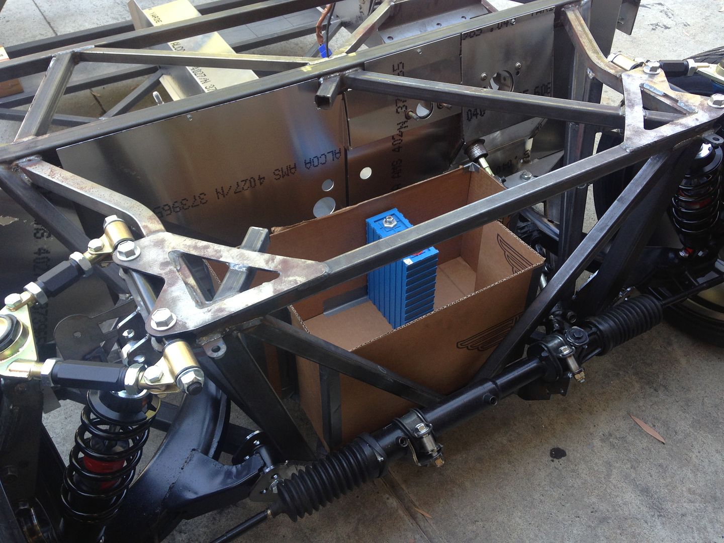
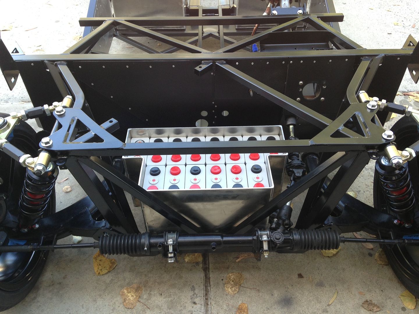
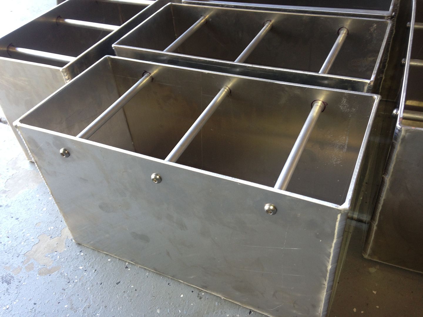
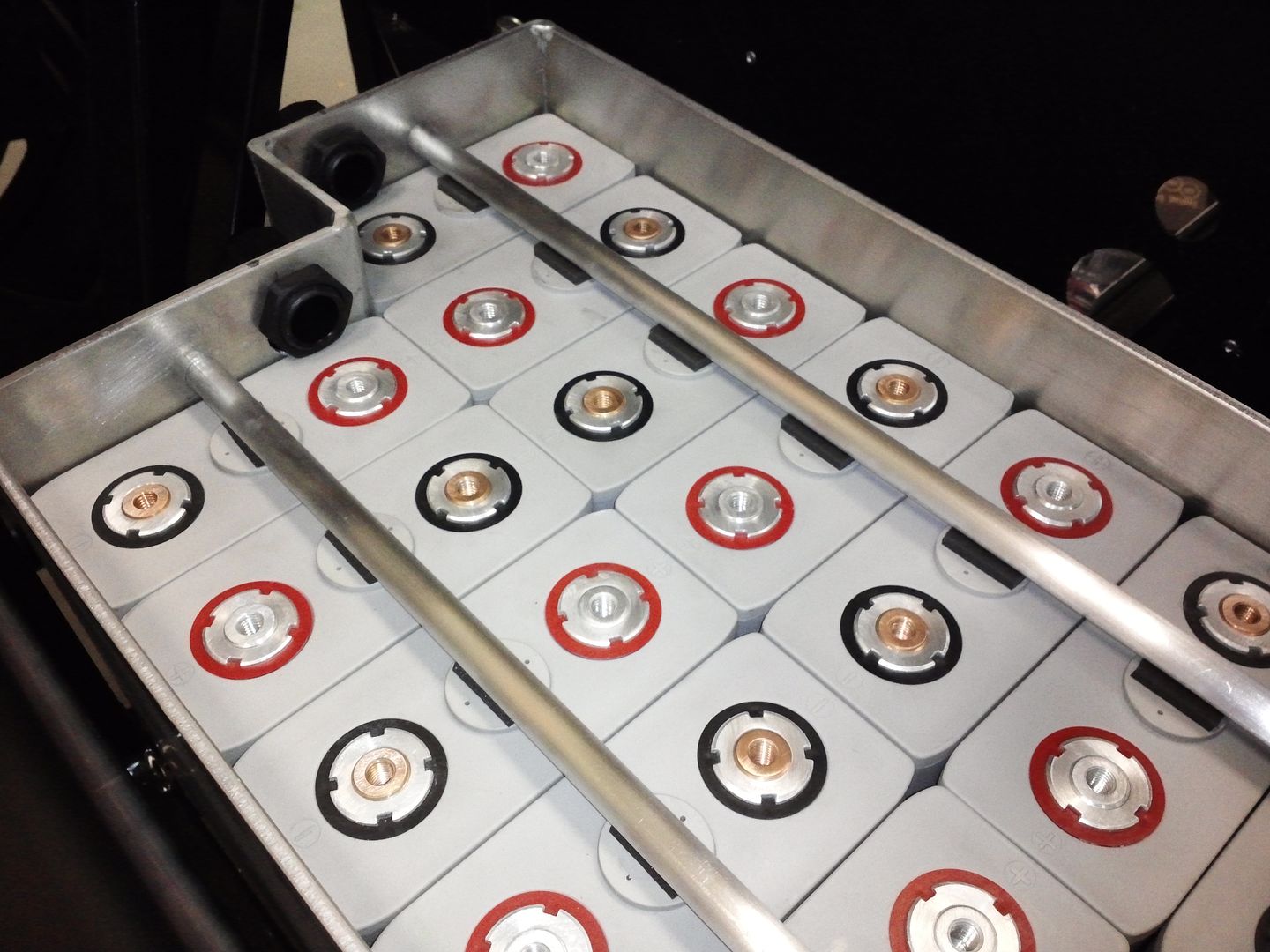
. 96 cells is crazy and 110+booster pack is next to impossible. We'll see! Post some pics! Btw, I'm definitely using the tranny tunnel for batteries, even if I have to modify the structure. The idea is that the CALBS are setup like Eric's with the addition of the tunnel, and maybe there will be additional batteries on top of the other ones (in the back up to 60-40 weight distribution). I'm also thinking the booster pack will be in front of the front axel and with some serious active cooling (think copper/alu plates to hold the batteries with recirculating transformer oil and a heat exchanger in front). I haven't calculated the volume for the booster pack though.

    You gotta remember I have 2 motors and 2 controllers. I can have a pack and motor for distance and another for acceleration/braking regen. That doesn't mean I'm not going to try to combine them with close monitoring (watching currents coming out of each pack). If they don't balance well, I could add an IGBT to the CALB pack to limit its current output. So how do I control which motor gets what torque control signal (i.e. gas pedal voltage) if I split the packs? I'll be using an onboard ARM computer (cubieboard) to manage that. The computer reads the signal from the pedal, then decides which motor does what. The idea is that the CALB pack never goes over 4C or even 2C in normal city driving. The other pack gets all the regen and handles the voltage peaks. The computer also decides which pack gets the regen. In the real world you rarely accelerate for more than 15 seconds, so a pack that can take 600A for that amount of time is all I need. In any case, that project is at the end of the rainbow. I still have to make this thing move.
    Last edited by Speedy G; 06-04-2015 at 11:08 AM.

  13. #93
    Senior Member
    Join Date
    Oct 2014
    Location
    Redondo Beach, CA
    Posts
    161
    Post Thanks / Like
    Fair enough ... it's definitely been a struggle. The design doesn't close all the way now, but I hope after I modify the frame to fit the engine, I can get a better idea of how many batteries I can stack in the gas tank area. I played with the idea of installing batteries in the center tunnel area, but I'd only be able to fit a few. Even then I'd have to raise the height by a few inches. There's room forward of the gear shifter, but I was thinking that the increased resistance of the interconnecting cables made more sense to try and consolidate battery packs to as few locations as possible.

  14. #94
    Senior Member
    Join Date
    Oct 2014
    Location
    Redondo Beach, CA
    Posts
    161
    Post Thanks / Like
    Will the Cubieboard also switch charging or do you plan to have two chargers for each pack?

  15. #95
    Senior Member
    Join Date
    May 2013
    Location
    Colombia
    Posts
    222
    Post Thanks / Like
    That's the thing, my motor controllers each has a battery pack charger. I can plug each to a 110V plug or up to 250V. Version 2 of the controllers even has a UPS mode, meaning you can hook up your house to the inverter and if you lose power, the battery pack will drive your house for a while.

    The cubieboard has other tasks though. I'm thinking it'll be monitoring the batteries, managing traction control, and eventually, it'll rpm match the tranny with the motor for automated shifts. It'll also drive the automated shift actuators. The idea is to use the tranny in 2nd gear until I can get myself to spend on a dog engagement kit for the subie tranny. Once I do that, I'll be paddle shifting a dog engagement tranny with no clutch. I'll release all the code and schematics on the board once I'm done.

    Speedy G
    Last edited by Speedy G; 06-05-2015 at 03:12 PM.

  16. #96
    Senior Member
    Join Date
    May 2013
    Location
    Colombia
    Posts
    222
    Post Thanks / Like
    Hey John,

    I looked at the Cobalt batteries out there (site still down though, so not John Metric's ). It looks like those suffer from thermal runaway. That means monitoring the temperature of every cell so it doesn't come close to 130C. I'm not sure I want that in my car. It's like knowing the flash point of gasoline is 280C, and running your turbo down pipe 3 inches from the tank... too close for comfort. Do send me the specs, but I think I may go with the A123 cells. The burst pack will only weigh 80 lbs with dimensions of 1.6ft x 1.6ft x 1ft.

    Btw, I think it's awesome that the fastest Miata on the quarter is electric.

    P.S. The site is up actually. It's ampahaulic.com. I sent them an email. I'm thinking their pack will go for something like 5 grand which might be cheaper than the A123s.

    Speedy G
    Last edited by Speedy G; 06-05-2015 at 06:09 PM.

  17. #97
    Senior Member
    Join Date
    Jan 2014
    Location
    Ontario, Canada
    Posts
    141
    Post Thanks / Like
    Quote Originally Posted by Speedy G View Post
    Nice!! I'm very interested. It's just what I need!
    No it's not... Don't be mixing LiFePo4 with RC Lipo.

  18. #98
    Senior Member
    Join Date
    Jan 2014
    Location
    Ontario, Canada
    Posts
    141
    Post Thanks / Like
    Quote Originally Posted by ninjanick View Post
    Are you worried about mix and matching capacities if you use your A123 pack combined with a CALB pack?
    Booster pack is used in parallel. Capacity adds. Make the voltage the same. One charger. It looks like one pack to the charge and the discharge device. No need to manage anything. . . except perhaps heat on the booster pack if u bust it a lot.

  19. #99
    Senior Member
    Join Date
    Jan 2014
    Location
    Ontario, Canada
    Posts
    141
    Post Thanks / Like
    RC Lipo is the best place to go for 1/4 mile power. I would never put it in a daily driver or a hot rod. Maybe in track car. . . but this stuff does need a BMS..... and a good one at that. And I wouldn't charge it in my garage.... at night.

    Quote Originally Posted by Speedy G View Post
    Hey John,

    I looked at the Cobalt batteries out there (site still down though, so not John Metric's ). It looks like those suffer from thermal runaway. That means monitoring the temperature of every cell so it doesn't come close to 130C. I'm not sure I want that in my car. It's like knowing the flash point of gasoline is 280C, and running your turbo down pipe 3 inches from the tank... too close for comfort. Do send me the specs, but I think I may go with the A123 cells. The burst pack will only weigh 80 lbs with dimensions of 1.6ft x 1.6ft x 1ft.

    Btw, I think it's awesome that the fastest Miata on the quarter is electric.

    P.S. The site is up actually. It's ampahaulic.com. I sent them an email. I'm thinking their pack will go for something like 5 grand which might be cheaper than the A123s.

    Speedy G

  20. #100
    Senior Member
    Join Date
    Oct 2014
    Location
    Redondo Beach, CA
    Posts
    161
    Post Thanks / Like
    Quote Originally Posted by Gary Livingston View Post
    Booster pack is used in parallel. Capacity adds. Make the voltage the same. One charger. It looks like one pack to the charge and the discharge device. No need to manage anything. . . except perhaps heat on the booster pack if u bust it a lot.
    Are you worried about internal resistance differences between cell technologies/manufacturers? I'd imagine you'd be cycling the lower capacity "booster" pack quite frequently.

  21. #101
    Senior Member
    Join Date
    May 2013
    Location
    Colombia
    Posts
    222
    Post Thanks / Like
    Well, I think Gary is referring to the fact that those cells probably aren't very consistent, and they also suffer from thermal runaway. If you heat them up over 130 degrees celcius, they'll catch fire. Since they're not very consistent, you could discharge one at 100C and it would be ok, and the next could heat up to 130 C and blow up. I'm not sure why he calls them RC LiPo though.

    I was already thinking the A123s look like a better option. The only issue is where to get them. I've only seen 26650 batteries out on the market, without screws. Soldering 550 cells in series is not quite the assembly job I wanted for this car. Gary, any clue where i can get them?

  22. #102
    Senior Member
    Join Date
    Oct 2014
    Location
    Redondo Beach, CA
    Posts
    161
    Post Thanks / Like
    Have you looked at Headway cells? They have screw terminals and might be an easier cylindrical option to assemble. If you are sold on cylindrical, have you looked at bulk buying Samsung or LG 18650s? They seem to be more readily available than the Panasonic option.

  23. #103
    Senior Member
    Join Date
    May 2013
    Location
    Colombia
    Posts
    222
    Post Thanks / Like
    Can they do 50C though? My main cells will be CALB. The booster cells are the ones I'm worried about.

  24. #104
    Senior Member
    Join Date
    Oct 2014
    Location
    Redondo Beach, CA
    Posts
    161
    Post Thanks / Like
    The Headway 40152 cells are 15aH with a max discharge or 10C whereas the 38120 cells are 10aH with a max discharge of 10C.

  25. #105
    Senior Member
    Join Date
    Jan 2014
    Location
    Ontario, Canada
    Posts
    141
    Post Thanks / Like
    Quote Originally Posted by ninjanick View Post
    Are you worried about internal resistance differences between cell technologies/manufacturers? I'd imagine you'd be cycling the lower capacity "booster" pack quite frequently.
    Not worried about it..... that's what makes this method work. When the draw is low/slow. . . the discharge is balanced. When you stomp on it, the lower resistance booster cells try and support the voltage (drop) and therefore give up more current. When you let off. . . they recover with the energy from the range cells. So, you need a strong cycling cell capable of higher C rate like ones used for hybrid packs. . .like the A123 nano cells. Headways are oookayyish, if you spend the time to sort out the week ones. That's the problem. lots of guys build nice packs with them and loose 2 or 3 % of their cells.
    IF anyone wanted to use RC lipo in a car, the only place I would get it from is a chap in England who spends a lot of time weeding out the weak ones. . . even then, I wouldn't trust it for a daily driver.

  26. #106
    Senior Member
    Join Date
    Oct 2014
    Location
    Redondo Beach, CA
    Posts
    161
    Post Thanks / Like
    Are you referring to the A123 Iron Phosphate batteries? I've only really seen them on Ebay. I made a small battery pack out of Dewalt cells for my motorcycle. Worked great for a few years till I moth balled the bike in the garage and let it drain completely. I imagine putting a cell pack of those types would be expensive. Do you calculate total depth of discharge for the booster pack for the amount of power/time you need to size the booster? I would imagine if too small, you'd overdischarge the booster?

  27. #107
    Senior Member
    Join Date
    Jan 2014
    Location
    Ontario, Canada
    Posts
    141
    Post Thanks / Like
    Yes, A123 LiFePo. I have used the 32157's and the 32113's both rugged cylindrical cells. The capacity of the pack and C rate will determine the extent of the boost. You will never overdischarge the booster pack . . . unless you overdischarge the whole pack. Just think about it. . . the higher C rate cells are sitting at the same voltage as the rest of the pack. If you draw on the whole pack at a high rate, the lower resistance cells will prop up the voltage of the pack and since they sag less will give up a high percentage of the current. But as the booster pack gets closer to empty the main pack will take over. The net result is just less boost. You will never drop below what the main pack delivers.

  28. #108
    Senior Member
    Join Date
    May 2013
    Location
    Colombia
    Posts
    222
    Post Thanks / Like
    The thing is that you do have to watch out that you don't draw too much current from the main/booster pack. Say I draw 600 amps out of my 110sp6 A123 pack and 400 amps out of my main pack (CALB). Once most of the juice is gone from the A123 pack (trying to keep the voltage up), the current comes out of the main pack. So if my main pack was initially doing 4C, now it's doing 10C. All I'm saying is that it's good to know where your current is coming from if you do use a booster pack so as not to damage your main pack. It could also happen that if your batteries are too different, the booster could supply say 8/10 of the current, and maybe that would be too much, even for the booster pack. That's why I'm not totally sure what I'm doing yet. If the A123's prove to be "compatible" with the CALBs, I may use the main and the booster battery packs in parallel. If they prove too different in terms of resistance, then I'll use my two controllers and software to determine which pack and which controller is supplying the current.

  29. #109
    Senior Member
    Join Date
    Jan 2014
    Location
    Ontario, Canada
    Posts
    141
    Post Thanks / Like
    True enough, . . but all you really need to do is program a voltage limit under load. Decide what voltage you will allow the pack to sag to.
    There is no issue with "compatibility" , just match the voltage. A123's are actually 3.3 nominal so even less of an issue depending how many you put in the pack.
    As I said somewhere before,. . . I wouldn't go down this road of main and booster pack if I was starting fresh like most here are. I did it because I already had the range pack and wanted to prop it up. Try to select a battery that will give you what you need without having to build two packs. CALB are great range cells, but they aren't high performance and they're not the only cells.

  30. #110
    Senior Member
    Join Date
    May 2013
    Location
    Colombia
    Posts
    222
    Post Thanks / Like
    K, a bit of an update. Remember I have twin 2 year old girls so my time is scarce. I'm mainly confined to 3-4 hours a week if that on Saturday mornings. So what's up? Well, the first thing is that I finished the drilling and I've attached a video from part of it. It's essentially repetitive and mind-numbing. Here's a video from the first day. After that it's all looks the same:

    https://youtu.be/E9Nmw-YbaWw

    There's a few things to be learned from it:

    The first is that drill bits matter. I tried regular high speed steel, titanium coated, but ended up using cobalt steel drill bits. They're expensive, but things get done faster and better with the proper tool. Titanium ones are ok, but they don't last forever.

    The second thing is that FFR really does a poor job with aluminum forming. Aluminum has memory, so when you bend it to 90 degrees it'll probably end up being at 70 deg when you try to install it. They obviously don't take this into account. That means the dead pedals are extremely tough to install since nothing really fits. Add to that that the steel sheet flooring is warped due to welding, and what you get is essentially a solidworks wish it were true design that doesn't at all apply to the reality of the build. On top of that, it's supposed to be water tight! Not surprised, but it shows there's definitely a long way to go in terms of engineering design. Someone said we're not building BMWs, I can see that now. Then again the fun part is fixing it my way (not yet)... Here's a pic of what I'm talking about:

    DSC_0029-2.JPG

    Check out the space below the corner of the dead pedal. Also, check out how I had to bend the panel so it would fit. You can see the large vertical panel is curved since I couldn't find a way to bend it to beyond 90 degrees (metal table gets to 90 degrees). This is after shaving off a few of the parts with sheet metal shears btw.

    Speedy G
    Last edited by Speedy G; 11-03-2015 at 02:39 PM.

  31. #111
    Senior Member
    Join Date
    May 2013
    Location
    Colombia
    Posts
    222
    Post Thanks / Like
    Soo... A few things that might be useful to people:

    A good place to find subaru parts http://parts.andersonsubaru.com/. They have the standard subaru catalog drawings, but you click on the part and it takes you to the part number, etc. It's pretty well done, but they're not cheap. I found www.subarupartsdepot.com and www.quirkparts.com to be much cheaper. The best part of it is that andersonsubaru.com has hardware part numbers which are missing on most of the other sites I've checked. I bought the hardware from quirkparts.com since I found them after I'd already orderer most of the other stuff from subarupartsdepot.com.

    Subaru parts list for the front suspension (missing the splash guard or back-plate):

    SubaruPartsDepotRearSusp-0.jpg
    SubaruPartsDepotRearSusp-1.png


    Subaru parts list for suspension hardware and rear suspension w/o knuckle or disc brakes:
    PartsWrxRearSuspNoHubNoKnuckleNoDiscBrakes-0.png
    PartsWrxRearSuspNoHubNoKnuckleNoDiscBrakes-1.png

    Also Fastwrx.com sells hardware kits for the rear suspension:

    http://www.fastwrx.com/products/suba...k-hardware-kit
    http://www.fastwrx.com/products/suba...o-knuckle-bolt
    Last edited by Speedy G; 11-03-2015 at 05:56 PM.

  32. #112
    Senior Member
    Join Date
    Jun 2015
    Posts
    678
    Post Thanks / Like
    So far, we have used NONE of the alum supplied in the kit. first of all, the numbering/identification system did not exist. Secondly, when we did try to use a bent piece, we noticed cracks forming at the bend, which didn't make us happy.

  33. #113
    Senior Member
    Join Date
    May 2013
    Location
    Colombia
    Posts
    222
    Post Thanks / Like
    Also, I've been trying to install the 2015 STI steering rack. The differences are barely noticeable. It looks like the diameter of the rack is larger than the 2006 rack since the bolts provided are too short. Also, the driver's side needs a couple of washers or some kind of shim on one of the screws to level it out. On the passenger's side, you could use the provided bracket, I guess, but I bought a nicer bracket from Hindsight. Here's some pics. I took the liberty of using Hindsight's pics for the regular '07 rack to compare:

    Attachment 47153

    2015STISteeringRack-2.JPG

    2015STISteeringRack-1.JPG

  34. #114
    Senior Member
    Join Date
    May 2013
    Location
    Colombia
    Posts
    222
    Post Thanks / Like
    I've been looking at batteries again. I think the perfect battery for the 818 AC high voltage motors (~360V ) is the CALB CAM72FI. Why? It's good to ~230Hp (~576A*300V), has decent range, and fits replacing the gas tank and the center tunnel with a modification of the rear firewall and a redo of the center tunnel. I'll definitely be using 110 CAM72FI cells for my range battery (main motor), and eventually for the secondary acceleration motor, a set of 110 A123 20AH pouches. The 110 CALB batteries have a nominal voltage of 352V and 302V at 8C (way less than a 10s pulse under 1/4 mile accleration). Also, the way they're constructed makes them easy to cool using fans since the batteries aren't touching each other.

    The new tank has a section that's 20cm deep, and the thin part is 10cm. The batteries are 13.5cm wide, so redoing the rear firewall means the passenger gains some leg room as well, but the driver maintains decent leg room. The tank and the center tunnel fit 80 batteries. The remaining 30 can easily fit in the back on either side of the tranny, or forward of the firewall. This way, most of the weight is distributed optimally. The A123 cells can later be added depending on where the additional weight is needed, but these don't need that much space since they'll be only 20AH.

    Replacing the center tunnel makes sense if you're using a Tesla style 1 gear gearbox of if you go for an automated 5mt (Mastershift, etc) since you won't have space for the shifter cables. I'll initially be driving only in second gear which is the equivalent ratio of a Borg Warner egeardrive tranny (8.28:1 vs 8 wiith a 4.11 ratio), so it won't be a problem for me. The center tunnel is 13.5 cm wide, just like the batteries, so the modified center tunnel will only be maybe an additional 1cm wider. However, the height will increase by like 10cm (~2.5 inches) to 25cm, which isn't much when you compare it to the tunnel in the original MR2.

    The weight for the 110 CAM72FI cells is 209kg (459 lbs). That sounds like a lot, but the subbie engine plus a full tank of gas weigh around 400lbs. A single one of my electric motors is 100 lbs, and the controller is probably 65 lbs, so It looks like mine will weigh around 200lbs more than a regular 818s build.


    Speedy G
    Last edited by Speedy G; 11-11-2015 at 03:35 PM.

  35. #115
    Senior Member
    Join Date
    Oct 2014
    Location
    Redondo Beach, CA
    Posts
    161
    Post Thanks / Like
    I've been trying to estimate voltage sag and was wondering how you came up with 50V at 8C. Was this actual testing? I tested a single CA 60aH cell with a PowerLab 6 and it measured 0.9mohms. Not sure how much better the FI technology is, but <0.8mohms is pretty good if including battery cables, bus bars, fuses and hardware.

    I assume you are using the plastic spacer ends for your batteries. How are you constructing the battery boxes? I'm planning on 1/8" Aluminum sheet metal with cross braces to secure the batteries in place to ensure they don't jossel around.

  36. #116
    Senior Member
    Join Date
    May 2013
    Location
    Colombia
    Posts
    222
    Post Thanks / Like
    Hey, I thought you'd chime in since you've been talking about batteries for a while. I just took the sag value from evtv.me (Jack Richard), he's also tested the CA cells which I think you have, and they seem to be able to do 10C. Here's the CAM72FI writeup:

    http://evtvindex.blogspot.com.co/201...y-16-2014.html

    There's a writeup also for the CA cells:

    http://evtv.me/2012/09/battery-joy-and-the-car-guy/

    Yes I'll be using the plastic spacers. My first idea was to reuse the gas tank for the battery but my tank has a different depth on the driver and passenger sides (10cm vs 20cm). I might still use the tank, modify the front to make it around 15cm deep and just brace the batteries together in packs of 60cm or around 20 batteries. I'll then attach the packs of 20 to the outer shell (tank). But then again, the aluminum sheet metal idea like Erik's sounds good.

    Also, I've been looking into battery cooling. I found this thermal image:

    http://jes.ecsdl.org/content/161/14/...expansion.html

    What that tells you is that if you cool the cathode, you'll effectively cool the whole battery and it'll also make the temperature more homogeneous. What that translates to in my book is that I'll be cooling the batteries from the top, which makes sense anyway. I'll be adding fans to extract the air from each end of the pack, and I'll have air intakes after every battery, not sure where yet, but the idea is that cold air gets to every cell.

    Speedy G

  37. #117
    Senior Member ehansen007's Avatar
    Join Date
    Mar 2011
    Location
    Aliso Viejo, CA
    Posts
    1,625
    Post Thanks / Like
    Not to hijack this thread or anything but this part of the build was the most important and most time consuming. Securing the batteries properly is paramount. From experience I can tell you that building your own boxes with aluminum is the best way to do it. I'm not sure I'd use the gas tank as you're going to want to secure the top of the batteries with something running across in case you ever go upside down. The tank is flimsy and may not have enough material to adequately secure the batteries. Also, they aren't thick enough to countersink the tapered allen bolts that secure the box through the bottom to the frame. You could run lugs at the bottom I'm sure but it will warp that metal. You'll also want to drill a few holes in the bottom for drainage in case, god forbid, any water gets in there, you'll never get it out!

    EV West was very adamant about this and showed me how to do it right. Cardboard goes a long way for sure and will help you figure out how and if boxes will go into position once built. Simply putting the batteries in configuration and moving cardboard around it worked great.

    Running the batteries up against each other wasn't a bad thing as they never got hotter as a pack as to surpass the mfg specs. Even when dumping 1000A at 10-14C at the track! But again, secure them properly as you don't want those arcing out in a crash or flip. Hope this helps.


    Then translating those into spec and given to a competent welder


    Then adding the security


    Last edited by ehansen007; 11-12-2015 at 11:48 AM.

  38. #118
    Senior Member
    Join Date
    May 2013
    Location
    Colombia
    Posts
    222
    Post Thanks / Like
    Hey Erik, thanks for your info. I've been using your thread extensively for battery and general info! At this point I think your build is the reference since non of us have finished ours. What about building an e-coupe?

    In any case, I just got the dimensions for the CALB CAM72FI batteries with the plastic spacers: 248.5mm H x 138.4mm W x 34mm D. What that means is that I can't fit 40 cells in the tank space, but rather ~35, and 32 in the tunnel. That means I need to fit ~43 cells either in the front or in the back. Judging from Erik's thread, it might be easier to fit them in the back, ~22 on each side of the tranny.

    The following image shows the CAM72FI cells with their separators:

    TSB-003-CAM72 Holder.jpg

    Notice the "partition fixer" has a way to attach it to the flooring. Also, the screws hold the batteries together and to the partition fixers.
    Last edited by Speedy G; 11-12-2015 at 05:23 PM.

  39. #119
    Senior Member ehansen007's Avatar
    Join Date
    Mar 2011
    Location
    Aliso Viejo, CA
    Posts
    1,625
    Post Thanks / Like
    That is pretty slick! Haven't seen that setup yet. And yes, there is a ton of room on each side of the tranny. SO much dead space in there. Looks like you guys know what you're doing so I'll just sit back and watch. And no, I don't have any interest in doing an e-car in the immediate future. I'd love to see the batter prices come down a bit first. I just want to drive my new cobra around a bit as well. If I did do another one, I'd do a hybrid for sure. Maybe electric front and a turbo hyabusa in the back or all of it in the back?

  40. #120
    Senior Member
    Join Date
    May 2013
    Location
    Colombia
    Posts
    222
    Post Thanks / Like
    Hey, long time no write... Little progress, but some. I've been stuck mostly due to missing parts. It's really hard to finish a system if you have to assemble, check for missing parts, look at the crummy subaru drawings and part numbers available on the net, buy, wait, reassemble, repeat.

    In any case, I've been assembling the brakes, suspension and steering simultaneously. Waiting on a few screws in the rear suspension, but I should be done by next week. The wilwood brakes are huge btw. They're going to look cool, and are definitely overboard.

    As far as the steering goes, I'm going to need to mod the frame. I'm using the 2015 STI steering rack. It's almost a good fit, but not. Below are the pics. Although I could theoretically use the provided mounts and add a few washers to the driver side, rear bolt, as people do on 2006 wrx's that would tilt the rack in 2 dimensions. The drivers side would be more to the rear and higher than the passenger's side mounts. Sooo... I'm going to cut and make a new mount... eventually. Definitely before I race it. Here's some pics:

    Here's the problem. The forward mount on the steering rack is way thicker than the aft one:
    SteeringRack-1.JPG

    That causes the rack to be further aft on the driver's side than on the passenger's side,
    SteeringRack-3.JPG


    and the driver's side is higher than the passenger's side, although it's not visible in this picture, but with a level it becomes clear:
    SteeringRack-2.JPG

    Since it's only the front driver's side mount, I think the easiest way to fix it is to cut and replace the mount on the frame. Also, on the second picture you can see that the plastic boot hits the frame, and that's without adding washers to the aft mount.

    Speedy G
    Last edited by Speedy G; 02-17-2016 at 07:20 PM.

Page 3 of 4 FirstFirst 1234 LastLast

Posting Permissions

  • You may not post new threads
  • You may not post replies
  • You may not post attachments
  • You may not edit your posts
  •  

Replica Parts

Visit our community sponsor