BluePrint Engines

Visit our community sponsor

Thanks Thanks:  0
Likes Likes:  0
Results 1 to 15 of 15

Thread: Eliminating the remote solenoid in Ron Francis Wiring?

  1. #1
    Administrator David Hodgkins's Avatar
    Join Date
    Feb 2011
    Location
    Corona del Mar, CA
    Posts
    6,063
    Post Thanks / Like
    Blog Entries
    7

    Eliminating the remote solenoid in Ron Francis Wiring?

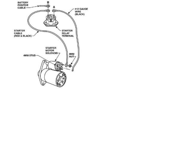
    Does anyone have a schematic of how to run power to the Ron Francis wiring while eliminating the remote solenoid? I'm going to run a mini starter with built in solenoid and I'm having trouble picturing how to wire it.

    Can anyone help me out?


    FFR 5369 Pin Drive, IRS, Trigos, Torsen, Wilwoods, FMS BOSS 302 "B" cam , Mass-flo. CA SB100 (SPCN) Registered
    Delivered 4/23/06. "Finished" 4/2012 (still not done!)


  2. #2
    Super Moderator vnmsss's Avatar
    Join Date
    Feb 2011
    Location
    California
    Posts
    649
    Post Thanks / Like
    Blog Entries
    13
    Great question, David.....I'm currently rewiring my Coupe, and have the same question. Also, would love wiring diagram or schematic using the Ron Francis harness and adding a kill switch for racing applications.

    Thanks!

    K
    #28 FFR Challenge Series
    #28 FFR Type-65 Coupe
    2011 Western Endurance Racing Championship
    2010 West Coast Champion
    Drive it.....Like you stole it!

  3. #3
    Senior Member 68GT500MAN's Avatar
    Join Date
    Feb 2011
    Location
    Fresno, CA
    Posts
    1,808
    Post Thanks / Like
    I will look through my build folders and see if I can find something. I kept the remote solenoid as a junction point and still used the solenoid on the starter.

    Karen, is the coupe in California or Nevada?

    Doug

  4. #4
    Mustang Convert bansheekev's Avatar
    Join Date
    Jul 2011
    Location
    Morgan Hill, CA
    Posts
    342
    Post Thanks / Like

    Mini Starter Wiring

    David,

    I think this will get you what you are looking for with the Ron Francis harness. The battery in this diagram is connected to the positive post on the starter (but doesn't show the start / trigger wire). I picked this up along the way on my build for my Coyote but if you just ignore the feed to the Coyote controls pack its the same. All the other wires are from the Ron Francis harness. The power feed to the Coyote Controls pack is an add on and not part of the Ron Francis harness.

    The only difference with what I did is run a #4 between the starter and the distribution post (mainly because I had extra #4 and the appropriate ring terminals laying around).

    BatteryWiring.jpg

    Kevin
    Last edited by bansheekev; 10-21-2014 at 04:39 PM.
    MKIV, IRS/TruTrack/3.55s, Coyote, TKO600, Wilwoods
    Delivered: 1/6/2012
    First Start: 1/19/2014
    First Go-Kart: 2/1/2014
    Graduation: 1/4/2015
    Graduation Thread

  5. #5
    Senior Member CraigS's Avatar
    Join Date
    Feb 2011
    Location
    Blacksburg, Va
    Posts
    4,728
    Post Thanks / Like
    Does the RF harness have a relay for the starter? If you ditch the remote solenoid, I would recommend adding a relay. If you decide to stick w/ the remote solenoid here is the way it should be wired. This gets it out of the solenoid function. It is now just a big relay for the starter.

    This is from the Ford tech on upgrading to a mini-starter.
    FFR MkII, 408W, Tremec TKO 500, 2015 IRS, DA QA1s, Forte front bar, APE hardtop.

  6. #6
    Senior Member 68GT500MAN's Avatar
    Join Date
    Feb 2011
    Location
    Fresno, CA
    Posts
    1,808
    Post Thanks / Like
    Looking at my roadster it matches what Craig shows in his diagram.
    Doug

  7. #7
    Administrator David Hodgkins's Avatar
    Join Date
    Feb 2011
    Location
    Corona del Mar, CA
    Posts
    6,063
    Post Thanks / Like
    Blog Entries
    7
    I want to bypass the remote solenoid. So it looks like I need a relay? Any suggestions on which I should use?

    I'm just getting into connecting everything up. I've laid out the harness in the chassis. Power from the battery hits a cut off switch and then... ?

    I was thinking of routing the 12v to a distribution bar on the 2x2 behind the dash:
    http://www.mcmaster.com/#terminal-blocks/=u9hw1m


    I assume there is a main + cable from the fuse panel that I could route from there?
    There should also be a wire from the fuse panel to the ignition switch. I would then route a wire from the switch to a new relay, which has a 4 gauge wire from the distribution bar? Then a 4 gauge from the relay to the starter?

    BTW When I wired my 1st roadster I used an I squared setup which is completely different, so I'm like a newbie on this subject. Be gentle...

    I had to look up how a relay works! I found this which is actually really good ate explaining it so I could understand:
    http://www.rattlebars.com/avalanche/relay_basics.html


    FFR 5369 Pin Drive, IRS, Trigos, Torsen, Wilwoods, FMS BOSS 302 "B" cam , Mass-flo. CA SB100 (SPCN) Registered
    Delivered 4/23/06. "Finished" 4/2012 (still not done!)


  8. #8
    Senior Member edwardb's Avatar
    Join Date
    Feb 2011
    Location
    Lake Orion, Michigan
    Posts
    10,567
    Post Thanks / Like
    Here's how I wired my Mk4 using a master switch and no firewall solenoid. Used a Breeze front battery mount. The battery plus goes to the master switch on the waterfall right below the dash. Then back to the starter.


    Off the switched side of the battery lead on the master switch, also took an 8 AWG lead into the dash area, and attached to a bus bar similar to what you pictured. This powers the Ron Francis fuse box and harness. You can see it just above the steering column. Used a mega fuse for the alternator lead, also seen in the picture.


    So in effect the master switch acts like the firewall solenoid or the distribution post in Kevin's schematic to collect the main power feeds. I used a mini-starter, so technically the firewall solenoid is not required. But without it, you're switching the blue starter lead directly through the ignition switch to energize the starter solenoid. Lots of debate about whether this is a good idea. Multiple threads on the subject. That's how my Mk3 is set up, and it's never been a problem. After all the discussion, did go ahead and put a HD relay on the blue lead back to the starter for this build to reduce the current across the ignition switch itself. But may or may not be required.
    Last edited by edwardb; 10-22-2014 at 08:52 PM. Reason: Removed duplicate picture.
    Build 1: Mk3 Roadster #5125. Sold 11/08/2014. Build 2: Mk4 Roadster #7750. Sold 04/10/2017. Build Thread
    Build 3: Mk4 Roadster 20th Anniversary #8674. Sold 09/07/2020. Build Thread and Video. Build 4: Gen 3 Type 65 Coupe #59. Gen 3 Coyote. Legal 03/04/2020. Build Thread and Video
    Build 5: 35 Hot Rod Truck #138. LS3 and 4L65E auto. Rcvd 01/05/2021. Legal 04/20/2023. Build Thread. Sold 11/9/2023.

  9. #9
    Senior Member CraigS's Avatar
    Join Date
    Feb 2011
    Location
    Blacksburg, Va
    Posts
    4,728
    Post Thanks / Like
    I understand that a lot of FFRs have a mini-starter and engage it right from the ignition switch. These are a few reasons why I recommend a relay. 1- A relay reduces the amp load through the switch. I have seen a fair number of threads about the ignition switch failing but no details on what the mode of failure is. Maybe a relay would help. 2-The other thing that comes to mind w/ this is that 20 yrs or so as a Lexus tech I found that they always use a starter relay. My feeling on that is that car manufacturers don't install anything on a car that isn't needed as they are always looking at costs. So, if they use a relay, I think it is a good idea. When you look at the fuse/relay box for any modern car you find they use relays for a LOT of systems. Keeping the higher amp loads out of the passenger compartment is a good idea.
    FFR MkII, 408W, Tremec TKO 500, 2015 IRS, DA QA1s, Forte front bar, APE hardtop.

  10. #10
    Senior Member edwardb's Avatar
    Join Date
    Feb 2011
    Location
    Lake Orion, Michigan
    Posts
    10,567
    Post Thanks / Like
    Quote Originally Posted by CraigS View Post
    I understand that a lot of FFRs have a mini-starter and engage it right from the ignition switch. These are a few reasons why I recommend a relay. 1- A relay reduces the amp load through the switch. I have seen a fair number of threads about the ignition switch failing but no details on what the mode of failure is. Maybe a relay would help. 2-The other thing that comes to mind w/ this is that 20 yrs or so as a Lexus tech I found that they always use a starter relay. My feeling on that is that car manufacturers don't install anything on a car that isn't needed as they are always looking at costs. So, if they use a relay, I think it is a good idea. When you look at the fuse/relay box for any modern car you find they use relays for a LOT of systems. Keeping the higher amp loads out of the passenger compartment is a good idea.
    Yes, lots of debate about the wisdom of taking the starter solenoid current through the ignition switch. Depending on who you believe, the current is 8-10-15-20-30 amps. There was a long debate about this on the other forum some months ago. Based on my research, it's more toward the bottom of this range. Hopefully isn't too much as the wire in the harness isn't that large. Either 10 or 12 AWG. Don't have it right in front of me. As I stated, I decided to go conservative on the MK4 and go ahead and add a relay to the starter wire, even though my Mk3 has been doing fine without. But the amps through that wire aren't any more than any other circuits, like the headlights, etc. Plus it goes right through the clutch safety switch. So keeping it out of the passenger compartment is neither an issue or possible regardless of how you wire it.
    Last edited by edwardb; 10-24-2014 at 01:12 PM.
    Build 1: Mk3 Roadster #5125. Sold 11/08/2014. Build 2: Mk4 Roadster #7750. Sold 04/10/2017. Build Thread
    Build 3: Mk4 Roadster 20th Anniversary #8674. Sold 09/07/2020. Build Thread and Video. Build 4: Gen 3 Type 65 Coupe #59. Gen 3 Coyote. Legal 03/04/2020. Build Thread and Video
    Build 5: 35 Hot Rod Truck #138. LS3 and 4L65E auto. Rcvd 01/05/2021. Legal 04/20/2023. Build Thread. Sold 11/9/2023.

  11. #11
    Senior Member Avalanche325's Avatar
    Join Date
    Nov 2011
    Location
    Jax Beach, FL
    Posts
    2,103
    Post Thanks / Like
    Quote Originally Posted by edwardb View Post
    Yes, lots of debate about the wisdom of taking the starter solenoid current through the ignition switch.
    The remote solenoid and the solenoid in a mini starter are pretty much the same thing, just in a different location. So either way the ignition switch is taking the same load.

  12. #12
    Senior Member CraigS's Avatar
    Join Date
    Feb 2011
    Location
    Blacksburg, Va
    Posts
    4,728
    Post Thanks / Like
    Edward and Avalanche the point of having a relay for the starter and/or for the headlights, or for any consumer, is that only the relay coil current (I suspect less than an amp) needs to go through the ignition switch in the passenger compartment. The ideal setup has the battery as the power source at one end of the circuit, and the consumer (starter or headlights etc) at the other. The relay is in between and as close to the battery as possible. This way the heavy wire is as short as possible for minimum voltage drop. Also the heavy wire from the relay to the consumer is only hot when the consumer is on. And to take keeping current out of the passenger compartment a step further, many systems are wired so the dash switch is switching the ground for the relay coil. Now the longest wire in the circuit is just a ground, so, if it were damaged and grounded out, the only thing that happens is that the consumer is turned on. That is how my radiator fan circuit is wired.
    FFR MkII, 408W, Tremec TKO 500, 2015 IRS, DA QA1s, Forte front bar, APE hardtop.

  13. #13
    Senior Member edwardb's Avatar
    Join Date
    Feb 2011
    Location
    Lake Orion, Michigan
    Posts
    10,567
    Post Thanks / Like
    Quote Originally Posted by CraigS View Post
    Edward and Avalanche the point of having a relay for the starter and/or for the headlights, or for any consumer, is that only the relay coil current (I suspect less than an amp) needs to go through the ignition switch in the passenger compartment. The ideal setup has the battery as the power source at one end of the circuit, and the consumer (starter or headlights etc) at the other. The relay is in between and as close to the battery as possible. This way the heavy wire is as short as possible for minimum voltage drop. Also the heavy wire from the relay to the consumer is only hot when the consumer is on. And to take keeping current out of the passenger compartment a step further, many systems are wired so the dash switch is switching the ground for the relay coil. Now the longest wire in the circuit is just a ground, so, if it were damaged and grounded out, the only thing that happens is that the consumer is turned on. That is how my radiator fan circuit is wired.
    Thanks for the basic electricity lesson. However most of what you described doesn't fit the OP's question. The question was the necessity and/or how to wire for a mini-starter without the firewall mounted solenoid. Not the little cube relays that are used for other switching, like the horn, cooling fan, etc. Avalanche325 makes a very good point. The 8-10-20 amps (whatever it actually is) to pull the firewall solenoid is likely no different than the built-in solenoid on the mini-starter.

    Unless you start modifying, little or no options to control what current is/is not in the passenger compartment using the standard Ron Francis harness. The highest current (100-200-300 amps, whatever) for the starter does stay outside between the battery and starter and firewall solenoid, if used. So that's not in question. The balance goes into the main Ron Francis fuse box in the passenger compartment and is distributed from there unless you modify it. The fuse box does come with several standard relays (horn, cooling fan, fuel pump) but these are all in the fuse box. Although some guys add them, the standard harness doesn't use relays on the headlights except maybe to switch between low and high beam, depending on how you choose to wire it. In either case, the current goes through the GM style headlight switch. Personally I find no issue with those relatively low current draws being in the passenger compartment.
    Last edited by edwardb; 10-25-2014 at 09:24 AM.
    Build 1: Mk3 Roadster #5125. Sold 11/08/2014. Build 2: Mk4 Roadster #7750. Sold 04/10/2017. Build Thread
    Build 3: Mk4 Roadster 20th Anniversary #8674. Sold 09/07/2020. Build Thread and Video. Build 4: Gen 3 Type 65 Coupe #59. Gen 3 Coyote. Legal 03/04/2020. Build Thread and Video
    Build 5: 35 Hot Rod Truck #138. LS3 and 4L65E auto. Rcvd 01/05/2021. Legal 04/20/2023. Build Thread. Sold 11/9/2023.

  14. #14
    Senior Member CraigS's Avatar
    Join Date
    Feb 2011
    Location
    Blacksburg, Va
    Posts
    4,728
    Post Thanks / Like
    I realized I was getting a bit beyond the OPs original question. Just trying to give some info that may help out for this question and in more general terms.
    FFR MkII, 408W, Tremec TKO 500, 2015 IRS, DA QA1s, Forte front bar, APE hardtop.

  15. #15
    Senior Member
    Join Date
    Feb 2011
    Location
    Southport, NC
    Posts
    511
    Post Thanks / Like
    Here is the diagram I think the OP wanted.


    The remote solenoid acts as a convenient way, when conveniently mounted, to attach the positive battery line and tap off of it on the solenoid post for power elsewhere. Some batteries are in the rear and the run to the front would usually run straight to the starter with no way of getting a positive line except off the starter.

    The second solenoid is just that a second solenoid. Two relays being used.

    George

Posting Permissions

  • You may not post new threads
  • You may not post replies
  • You may not post attachments
  • You may not edit your posts
  •  

Replica Parts

Visit our community sponsor