
Visit our community sponsor

Thanks:
1

Likes:
3
-
818 builder

I made my own spacers and brackets guys, it was not that much effort. I would think by now they had it down.It looks like FFR might still need to revisit the rack mounting to get it right. You will get it, your doing great so far. You get rings in, I hope that's settled.
818S frame #13 Jdm version 8 ej207
-
Senior Member

-
Senior Member
-
Senior Member
Time lapse of the short block assembly!
-
818 builder
818S frame #13 Jdm version 8 ej207
-
Senior Member
-
Moonlight Performance


Whew, glad you were able to get the bolt out! You two are making amazing progress.
-
Senior Member

Originally Posted by
Hindsight

Whew, glad you were able to get the bolt out! You two are making amazing progress.
Thank you. We have a slightly optimistic goal to have first start by Christmas, so we are trying to push at it a little each day. The engine keeps trying to set us back though!
On the bolt, when it broke we nearly had a heart attack there for a while.
When we first went to torque it (it was the first of the two smaller front bolts), something didn't feel right (we could feel it stretching, whereas the other larger bolts just tightened up and and clicked on the torque wrench). So, we un-torqued everything and pulled it back out, checked it and the head, seemed fine, and then went at it again, then "pop." Crap.
Luckily, as soon as we went at it with a LH drill the bolt actually backed itself out. We at first assumed it was just a bad bolt, so went at it again with one of the other crankshaft's bolts. It felt the same way (could feel that "stretching" feel again), and that's when we stopped and started "Nasiocing" and found out those were supposed to be only 7 ft lbs. We are just going to start with a set of 8 brand new smaller bolts, just in case any of the others were over torqued in their life due to the FSM's misprint.
-
Moonlight Performance
You are lucky it came out so easy. That almost never happens for me. But usually the bolts that break on me are siezed up and do so on removal attempt. I have always had to drill them out and add a helicoil. Major pain. I have also experienced that sinking feeling of over torquing a bolt into aluminum.
RE the manual, what year manual are you using? I checked my 06 manual and it does show the proper torque numbers (7 and 14 or something). If you two would like a copy, PM me your email and I will send it.
-
Senior Member
It is for an 02 wrx, which our heads are. Seems like it is just the instructions for the EJ205 that has the misprint, based other nasioc posts.
-
818 builder
It's off for the 02 bugeye, but than I believe got revised at some point once subaru techs starting breaking them. I prob should have mentioned that, but it has been like 10-12 years since I lived your pain, Great job getting it out, that's not always such a treat. I am hopeing to cart by Christmas, life's been busy lately or I would be driving it around again.
818S frame #13 Jdm version 8 ej207
-
Senior Member
LOL thanks Chris. Any other tips? The ones we found today were mostly lack of torque specs, including the valve cover gaskets (about 4 ft lbs, btw) and a few things.
We had today off, and our local Subaru dealership in Milford, CT (Dan Perkin's Subaru - speak with Gene if you ever call for parts) got our shimless buckets today, that we ordered yesterday! Also the 8 camshaft bolts and a few other assorted parts. Such great timing since we were holed up due to the snow today.
We torqued the head bolts for the 3rd or 4th time (ARP recommends re-torquing, and we actually got movement after our initial torque to the 2nd torque, but none after that). We installed the shimless buckets, torqued the cam shafts, and double checked the clearances on the shimless buckets to the camshafts using our feeler gauges - .010 for the exhaust, and .008 for the intake, and we were good to go. Closed up the valve covers!
Question for the Subaru gurus - do these threaded plugs that we marked in pink go in these locations? The machine shop pulled them out. They seem like they are just filler caps of a sort. There is also one on the backside of the engine where it meets the transmission.
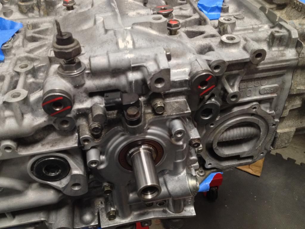
Next we added a shim to our 10mm oil pump (for a total of 3 shims, not sure if it had been previously modified). It seems like this is an area where everyone has a different opinion of what is the best way to go. From our research, it sounds like the 10mm pump should flow enough oil for our non-AVCS heads (AVCS heads should use the 11mm). The biggest issue is when the bypass valve opens and the effect it has. The 10mm pump is set to open the bypass valve at 85 psi, it drops to 75psi for the 11mm pump I believe. The more oil that is bypassed, the more everything heats up. Also, the risk of the oil beginning to aerate increases as the revs go up, due to the oil bypassing faster and faster. When the oil aerates, it can cause a sudden drop in oil pressure, which would not be good. Since we are planning on revving this engine higher than stock, this is critical for us to get right. Adding shims increases the psi that the bypass valve opens. This puts more pressure on the system overall, but will decrease the risk of us losing oil pressure at high rpms and with our increased bearing clearances. The real test will be when we start up the car and data-log and monitor the gauges. We will adjust the shims and/or the pump accordingly at that point.
Pulled this off:
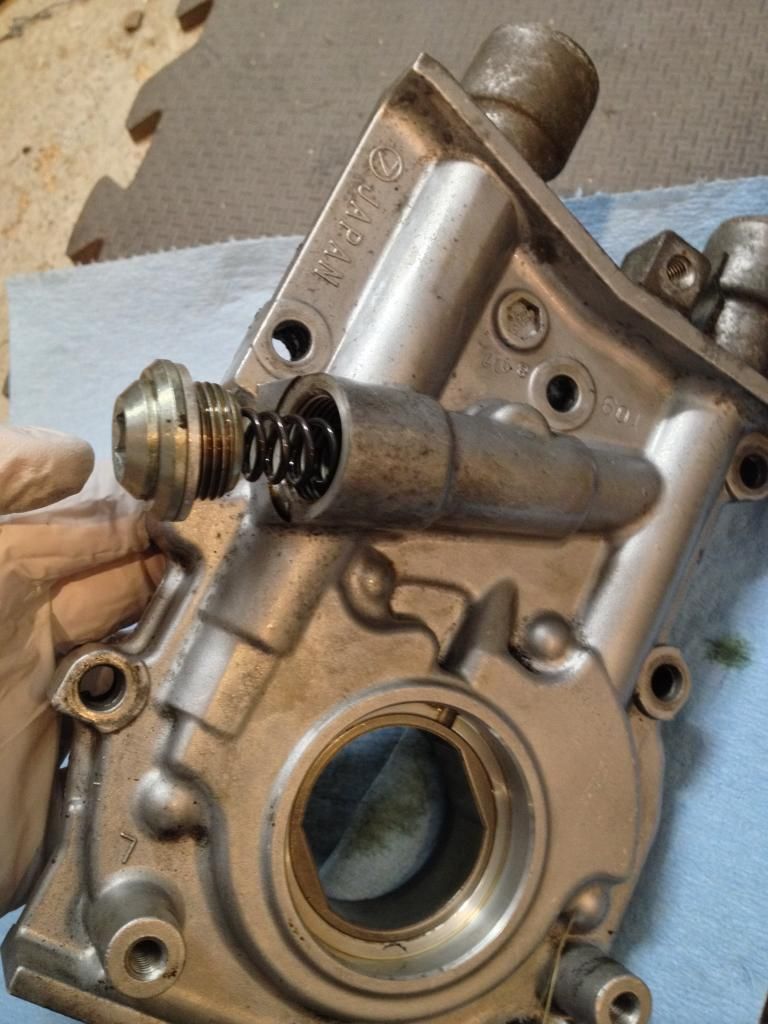
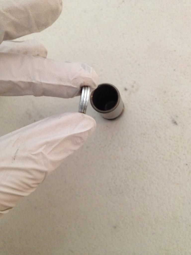
Pulled out the little sleeve to find two shims, added one more, and closed it back up.
Then we just gave the engine a good polishing 
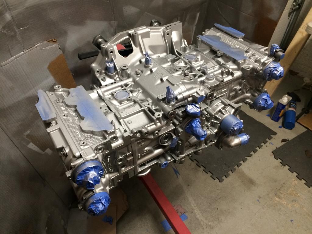
Just kidding... VHT Engine Enamel did the trick though (We had previously sand blasted it and it still didn't look great, but at least it prepped it for paint).
We hope everyone has a Happy Thanksgiving!
-
818 builder
Have a happy turkey day guys!! Looking great!!
818S frame #13 Jdm version 8 ej207
-
Senior Member
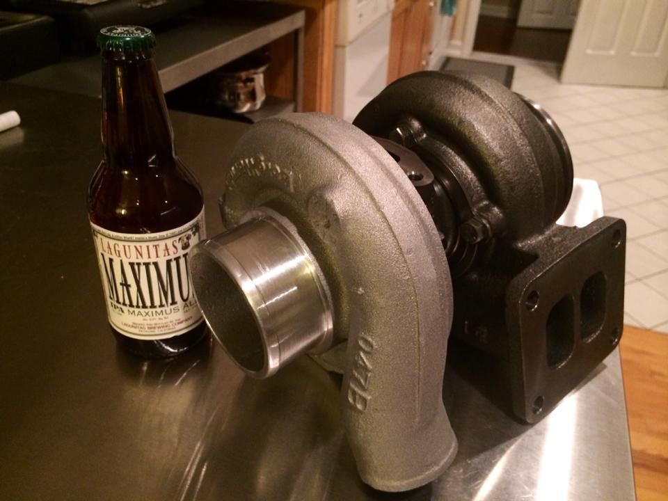
Came home from Thanksgiving to find Christmas! Wow, and this is the "little" Borg Warner... the S200SX 51mm with .83 a/r. At least we'll be able to ditch the water tank since all 24lbs of it is oil cooled!
-
That's a great turbo, especially for the price.
-
whats your plans for the uppipe and wastgate..
-
Senior Member
Andrew has access to and practice with TIG equipment, but we aren't quite sure yet. We are going to get the engine in and then see if we can fab it ourselves (starting with our Kinugawa twin scroll up pipe). Moore Performance makes a rotated up pipe with a t4 flange solution for the Subarus also that we will check into if we don't think we can do it ourselves (again no guarantee of 818 fitment though).
Our plan is to run dual EWG's, 38mm TiALs.
We will hopefully know in a week or so if we think we can make it fit without rotating. The turbo is a little bigger than we expected, lol. Twin scroll should be fun!
-
Senior Member
-
Senior Member
-
12-01-2014, 05:51 AM
#100
I think it goes to the power steering pump.
-
12-01-2014, 07:13 AM
#101
yep, power steering pump. ups the idle rev's when the pump kicks pressure out (iirc)
the other thing. the rubber hose that goes to the fitting on the front of the manifold (from the solenoid) that has a whole bunch of random "T"s on it, and that interesting looking black and tan thing.
this is the EVAP circuit. You can delete a LOT of the random "T"s and just go with the Solenoid from the manifold to the evap line from the tank/charcoal canister. Makes it much simpler and keeps the chance for boost/vacuum leaks down.
as for the plugs you were asking about. they are all OIL GALLEYS. make sure they're all sealed up good.
they are also really good for checking oil pressure and temperature. Just saying.
-
12-01-2014, 10:42 PM
#102
Senior Member
Originally Posted by
Samiam1017
I think it goes to the power steering pump.
Originally Posted by
Ironhydroxide
yep, power steering pump. ups the idle rev's when the pump kicks pressure out (iirc)
the other thing. the rubber hose that goes to the fitting on the front of the manifold (from the solenoid) that has a whole bunch of random "T"s on it, and that interesting looking black and tan thing.
this is the EVAP circuit. You can delete a LOT of the random "T"s and just go with the Solenoid from the manifold to the evap line from the tank/charcoal canister. Makes it much simpler and keeps the chance for boost/vacuum leaks down.
as for the plugs you were asking about. they are all OIL GALLEYS. make sure they're all sealed up good.
they are also really good for checking oil pressure and temperature. Just saying.
Thanks guys, much appreciated. Guess that one's not getting deleted
Do you have any sort of a visual that shows the evap line routing you are talking about? We are all about simplifying, but we still need to be emissions compliant.
The plugs are all sealed up except for one, which we are going to add a t fitting off of for our oil pressure and oil temperature gauges.
New video from the engine build up. Our Timelapse loves to cut out at the exciting parts, so no intake manifold. But, it is the entire short block to long block assembly!
-
12-02-2014, 11:16 PM
#103
This is going to be a nice high performance setup, ditch those TGVs!
I have a set of deletes and a ported/polished manifold for a drive by cable throttle if you need it.
-
12-03-2014, 02:05 AM
#104
Nasioc has a write up about it. It doesn't throw any cel. And I highly doubt anyone who understands how the system came stock will blame you for simplifying it
-
12-03-2014, 07:41 AM
#105
Senior Member

Originally Posted by
Aero STI
This is going to be a nice high performance setup, ditch those TGVs!
I have a set of deletes and a ported/polished manifold for a drive by cable throttle if you need it.
We would have liked to fully delete them, but this is a for-now compromise, unless our tuner can delete the code without a not-ready status
Originally Posted by
Ironhydroxide
Nasioc has a write up about it. It doesn't throw any cel. And I highly doubt anyone who understands how the system came stock will blame you for simplifying it
I haven't seen anything about a CEL-free TGV delete option.. Do you have a link? My understanding was that it was just an easy code to delete, but CT is picky on not-ready sensors. I'm trying to avoid having to make a shortened version of the TGV rods to activate the sensors.
-
12-03-2014, 07:56 AM
#106
Moonlight Performance
I asked Wayne that question and if we understood eachother correctly, he said ALL codes can be turned off in the ecu (not just cleared but totally disabled) and doing so will not effect readiness code. Might reach out to him or another experienced tuner to confirm.
-
12-03-2014, 09:38 AM
#107
Senior Member

Originally Posted by
xxguitarist
I haven't seen anything about a CEL-free TGV delete option.. Do you have a link? My understanding was that it was just an easy code to delete, but CT is picky on not-ready sensors. I'm trying to avoid having to make a shortened version of the TGV rods to activate the sensors.
All you'd have to do is drill out the actual valves off of the rods and shave away the metal from the interior runners of the aluminum housing. The rod would remain the same length and would be there to activate the sensors. I believe this is how you delete the valves without throwing a code and I was going to use this approach until I got a tactrix cable. Now I'm planning to completely delete the actuators, sensors, and rods and then clear the codes.
-
12-03-2014, 09:47 AM
#108
Senior Member
Andrew is going to call a tuner today to ask about some other things, so we'll check on the TGV's and removing "not ready" codes as well.
Also, I found a diagram that explains which evap items can be eliminated around the "T" section that Iron mentioned. According to Nasioc, deleting these will not cause a CEL and shouldn't give us a problem passing emissions. We aren't 100% sure how closely they "inspect" during the CT inspection or if this would even matter, since it is still uses the charcoal canister, but we are going to try it this way. This is how the JDM ver7/8 STi cars are setup, apparently.
purge_valve_bypass_JDM.jpg
Tamra
Building 818SR #297 picked up 10/25/14 with Andrew (xxguitarist)
First start 12/21/14,
First "drive" 1/17/15
First Dyno at EFI Logics 3/7/15- 310whp at 15psi for break in, full spool by ~3500rpm!
First autocross 3/29/15
1st Registered 818 in Connecticut 7/24/2015. 9 months - 1 day from kit pickup!
-
12-03-2014, 09:56 AM
#109
Senior Member
Originally Posted by
STiPWRD
All you'd have to do is drill out the actual valves off of the rods and shave away the metal from the interior runners of the aluminum housing. The rod would remain the same length and would be there to activate the sensors. I believe this is how you delete the valves without throwing a code and I was going to use this approach until I got a tactrix cable. Now I'm planning to completely delete the actuators, sensors, and rods and then clear the codes.
That's exactly what is pictured above...and is our plan, unless the tuner says it can be taken care of with the Cobb. The flaps are removed, the aluminum divider is cut out.. and I also thinned out the profile of the rods when they're in the "open" position..
-
12-03-2014, 10:02 AM
#110
Senior Member
Originally Posted by
xxguitarist
That's exactly what is pictured above...and is our plan, unless the tuner says it can be taken care of with the Cobb. The flaps are removed, the aluminum divider is cut out.. and I also thinned out the profile of the rods when they're in the "open" position..
Ahh, couldn't see your pic - my work firewall blocks photobucket. The uploaded pics and other photo sites seem to work fine though. As long as you've removed the valves and aluminum, that takes care of most of the obstruction. I only want to delete the rods to use the tgv sensor 0-5V input for data logging temps.
-
12-03-2014, 12:19 PM
#111
Senior Member

Originally Posted by
xxguitarist
That's exactly what is pictured above...and is our plan, unless the tuner says it can be taken care of with the Cobb. The flaps are removed, the aluminum divider is cut out.. and I also thinned out the profile of the rods when they're in the "open" position..
I installed GrimmSpeed PnP'd TGV deletes; from what I've read, this should be straight-forward to delete the CEL with the Cobb AP3 once I fire it up. Regardless of what the OBDII reports, the visual inspection of our SMOG check would catch a full delete. Hope if works for you! Luckily, with the SB100 option in CA, I don't have to worry about emissions (ironic, huh?).
-
12-03-2014, 12:33 PM
#112
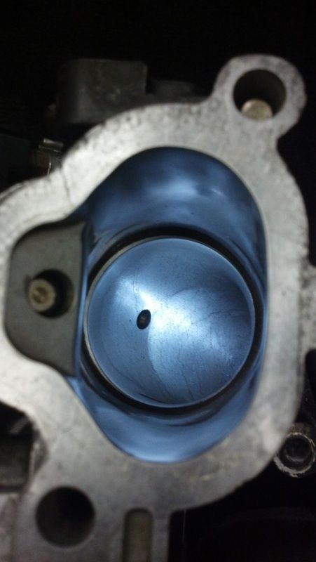
No restrictions... 
-
12-03-2014, 12:40 PM
#113
Moonlight Performance
Woah, why does that look sleeved?
-
12-03-2014, 02:27 PM
#114
Senior Member
We spoke with the tuning shop. Although they can delete the "not ready" codes, we are worried about the visual inspection. We will finish the TGV deletes next winter, after it's road registered
Also, it sounds like we will be able to get a base-map for our build for initial start-up, so we will proceed with installing the ID1000 injectors!
Back a few to when we were discussing those oil plugs on the top of the engine that make good ports for oil pressure and temp gauges... FYI in case anyone else is looking to do the same, it sounds like the factory oil sensor, when removed, will not trigger the oil light on the cluster. We'll probably remove that one and just have oil pressure out of one and temp out of the other (there aren't any others that are easily accessible), rather than having to do a T off of one.
Tamra
Building 818SR #297 picked up 10/25/14 with Andrew (xxguitarist)
First start 12/21/14,
First "drive" 1/17/15
First Dyno at EFI Logics 3/7/15- 310whp at 15psi for break in, full spool by ~3500rpm!
First autocross 3/29/15
1st Registered 818 in Connecticut 7/24/2015. 9 months - 1 day from kit pickup!
-
12-03-2014, 08:06 PM
#115
Tazio Nuvolari wannabe

I wonder if the DMV does any inspection for a "new" car or do you go to one of the stations that do inspections? I had a horrible experience with an inspection station that would not believe me that the Cobb downpipe had a cat in it. They saw a few mods and heard the car and told me to get lost. It would have passed had they not rejected me outright.
I may have a fitting that you can have that has a tap for oil temp or pressure. It works with AVCS fitting, however.
Motor looks great. You guys are doing great.
-
12-03-2014, 08:25 PM
#116
Senior Member

I have always run my oil temp from the oil pan. If the sender is in the block it will get block temp, unlike the coolant temp that has fluid flow around it the oil ports are dead head for pressure so there is no flow and I don't think the temp is accurate
-
12-03-2014, 08:57 PM
#117
818 builder
Originally Posted by
Tamra
We spoke with the tuning shop. Although they can delete the "not ready" codes, we are worried about the visual inspection. We will finish the TGV deletes next winter, after it's road registered
Also, it sounds like we will be able to get a base-map for our build for initial start-up, so we will proceed with installing the ID1000 injectors!
Back a few to when we were discussing those oil plugs on the top of the engine that make good ports for oil pressure and temp gauges... FYI in case anyone else is looking to do the same, it sounds like the factory oil sensor, when removed, will not trigger the oil light on the cluster. We'll probably remove that one and just have oil pressure out of one and temp out of the other (there aren't any others that are easily accessible), rather than having to do a T off of one.
Oil temp is best in pan guys. KB pan has a port and is a wise investment.
818S frame #13 Jdm version 8 ej207
-
12-03-2014, 09:19 PM
#118
Senior Member
Originally Posted by
Scargo
I wonder if the DMV does any inspection for a "new" car or do you go to one of the stations that do inspections? I had a horrible experience with an inspection station that would not believe me that the Cobb downpipe had a cat in it. They saw a few mods and heard the car and told me to get lost. It would have passed had they not rejected me outright.
I may have a fitting that you can have that has a tap for oil temp or pressure. It works with AVCS fitting, however.
Motor looks great. You guys are doing great.
Thanks Glyn! The inspection for kit cars is only at one DMV location in Waterbury, no other options, so we'd better make a good first impression. It has to pass an emissions test separately as well. Do you know what the thread pitch is? We need M20x1.5 to 1/8NPT.
Originally Posted by
D Clary
I have always run my oil temp from the oil pan. If the sender is in the block it will get block temp, unlike the coolant temp that has fluid flow around it the oil ports are dead head for pressure so there is no flow and I don't think the temp is accurate
We were thinking of the recently used oil temp as being beneficial to know as opposed to the reservoir temp, but didn't think about the temp not being accurate. That is something to consider for sure.
Originally Posted by
metalmaker12
Oil temp is best in pan guys. KB pan has a port and is a wise investment.
We already have an STI oil pan. We are considering doing the oil temp from the pan, but just wanted to check clearance to the ground. As ours is OEM, it would have to be through the drain plug, which of course is at the lowest point.
Tamra
Building 818SR #297 picked up 10/25/14 with Andrew (xxguitarist)
First start 12/21/14,
First "drive" 1/17/15
First Dyno at EFI Logics 3/7/15- 310whp at 15psi for break in, full spool by ~3500rpm!
First autocross 3/29/15
1st Registered 818 in Connecticut 7/24/2015. 9 months - 1 day from kit pickup!
-
12-03-2014, 09:33 PM
#119
Senior Member
We installed our Killer B pickup and windage tray tonight, our new STI oil pan, and our new OEM oil cooler and oil filter. We decided to get a new oil cooler as insurance, since we didn't know the previous history of this motor (plus it had ACL bearings in it when we initially opened it up, meaning it had a bearing failure at some point in its life). After reading too many horror stories about not being able to get the metal particles out, we decided not to risk it (despite the fact that our existing oil cooler did not have any grit come out when I cleaned it).
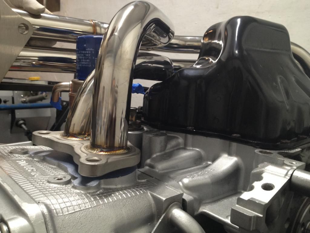
In our excitement, we decided to test fit our Kinuguwa Twin Scroll Headers... only to find they didn't fit. They hit the STI oil pan and have about 1/4" before they would reach the heads. Has anyone experienced this? Any ideas on how to resolve the issue? We have reached out to Flatirons Tuning who we purchased the kit from and are awaiting their response.
The good news is that they sit flush with the pan with the 1/4" gap, so we hopefully shouldn't have too big of an issue with them hanging below the frame rails too far. Does anyone know if the STI oil pan hangs below the frame rails?
Tamra
Building 818SR #297 picked up 10/25/14 with Andrew (xxguitarist)
First start 12/21/14,
First "drive" 1/17/15
First Dyno at EFI Logics 3/7/15- 310whp at 15psi for break in, full spool by ~3500rpm!
First autocross 3/29/15
1st Registered 818 in Connecticut 7/24/2015. 9 months - 1 day from kit pickup!
-
12-03-2014, 10:25 PM
#120
818 builder
Sti pan does not hang below, the KB pan does barely and my headers kinda lined up with that pan. Uncommon headers usually always have fitment issues even the larger names have fitment issues, you might be able to heat the header tube and bend it just out of the way enough. That's what I do if it's close( up to a 1/4 clearance issue) over that and other mods might need to be done.
818S frame #13 Jdm version 8 ej207
 Posting Permissions
- You may not post new threads
- You may not post replies
- You may not post attachments
- You may not edit your posts
-
Forum Rules

Visit our community sponsor


 Reply With Quote


