Forte's

Visit our community sponsor

Thanks Thanks:  0
Likes Likes:  0
Results 1 to 10 of 10

Thread: I'm no electrician

  1. #1
    Member Pirate's Avatar
    Join Date
    Aug 2013
    Location
    Georgia
    Posts
    68
    Post Thanks / Like

    I'm no electrician

    Took on the task of wiring my dash this week and so far I think, think being the key work, that I am on the right track. So I would appreciate if yall could take a look at the pictures I am going to attach and let me know if you see anything wrong, or advice, and any tips going forward. I have the FFR vintage gauges with the RF harness. I am running a Forte 347 carb, no heat or air, Speedo, tach, oil pressure, H2O temp, fuel, Voltage and a clock. I am going to wire the manual switch for the fan but am considering the auto thermostat, I also have a switch for high beams, hazard and turn signals. Also, I didn't take a picture of it but the voltmeter gauge has the daisy chain and one other wire coming out the back but I do not see any wire on the RF harness that says Volts, will this run directly from the daisy chain or do I need to use something on the RF harness.

    Thanks,

    Chris

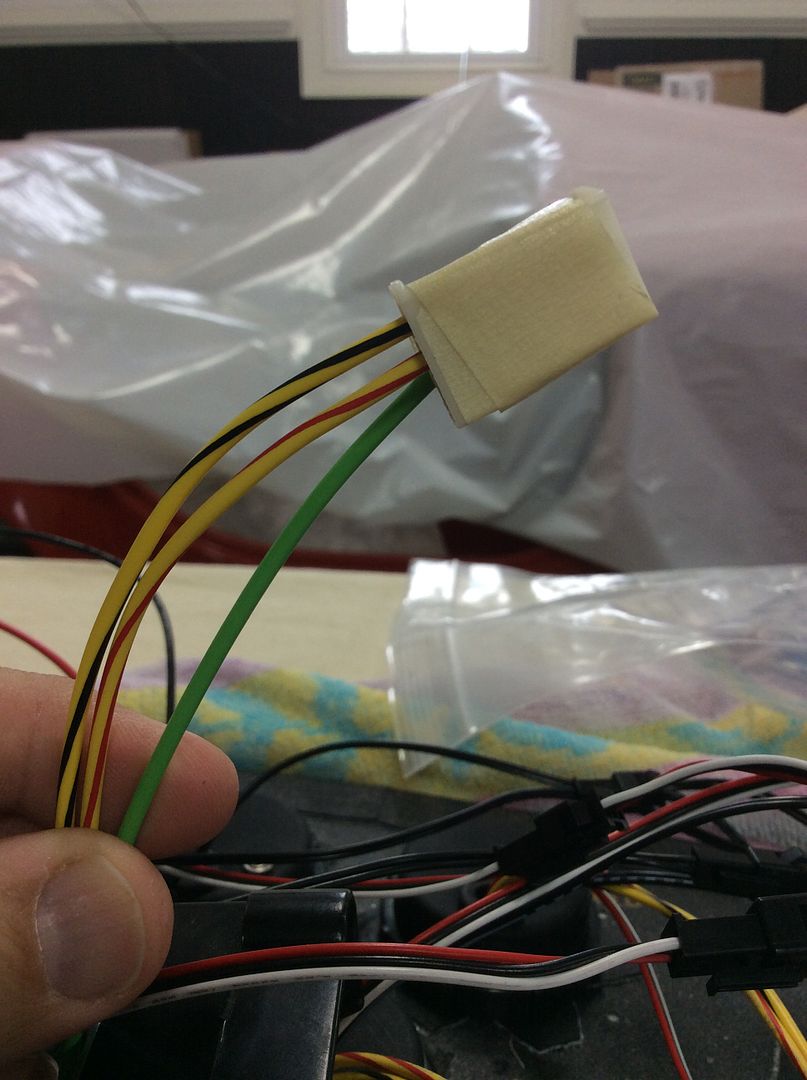
    First picture is of daisy chain for the instruments, I used both daisy chains.

    [IMG][/IMG]

    Second pic of black daisy chain for dial lighting taped to a ground and a light wire off of the RF harness.
    [IMG][/IMG]

    third pic is of the red, white and black daisy taped to brown gauge feed, white light feed and ground.
    [IMG][/IMG]

    this pic is speedo wires, two from both the RF harness and the speedo gauge.
    [IMG][/IMG]

    purple tach wire from RF to Tach gauge wire
    [IMG][/IMG]

    I don't know who spelled this wire but its the Water Temp to Water temp gauge. Question is there are two wires that come off the gauge?
    [IMG][/IMG]

    Oil pressure, again two wires off of gauge and only one RF wire
    [IMG][/IMG]
    Last edited by Pirate; 12-21-2014 at 03:18 PM.

  2. #2
    Member Pirate's Avatar
    Join Date
    Aug 2013
    Location
    Georgia
    Posts
    68
    Post Thanks / Like
    Couple of more pictures.


    Fuel gauge, and again two wires off of gauge and only one wire on RF harness
    [IMG][/IMG]

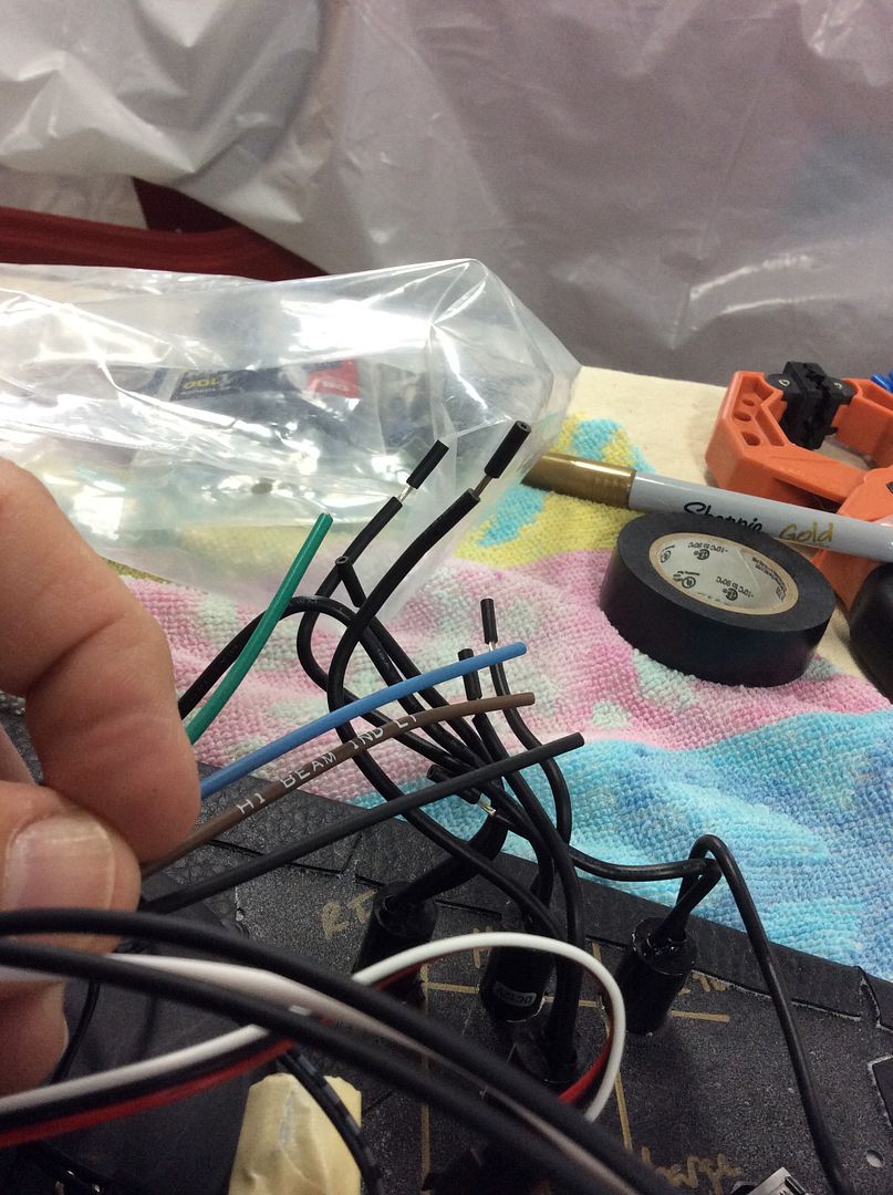
    Last picture for now is of the turn signal, high beam and the red light that go on the dash above steering wheel column and the RF wires. Brown is high beam, and the green and blue are for the turn signals. I am trying to figure out how to wire the red light. the black of course is the ground.
    [IMG][/IMG]

    Thanks,

    Chris

    PS. thought of another question, is it better to solder the wires together and shrink wrap them or what?
    Last edited by Pirate; 12-21-2014 at 03:20 PM.

  3. #3
    Senior Member DaleG's Avatar
    Join Date
    Mar 2013
    Location
    Prescott, AZ; formerly from the Bay Area
    Posts
    829
    Post Thanks / Like
    This gem from Jeff Kleiner should help:

    Jeff Kleiner’s WIRING DIRECTIONS
    The Speedhut/FFR Classic gauges use 2 wire senders while the RF harness is set up for one wire so I recommend doing kind of a hybrid that will incorporate the pigtails with the black/white wires. You'll need to power up all of the gauges on their red wire by connecting them to the brown "gauge feed" wire in the harness. Also connect the black "ground" wire in the dash harness to each of the gauges' black wires. You will carry the tachometer signal from the coil on the purple "coil-tach" wire that runs all the way through in the sending units subharness. The speedo signal comes from the trans through the green and gray wires which will join the yellow/red and yellow/black wires on the gauge. Polarity is not important as it is only counting pulses. For the coolant temperature and oil pressure gauges run the long pigtail with the yellow/red and yellow/black wires to their respective senders. Once again polarity is not an issue because these are reading resistance. The voltmeter has no sender, the gauge power and ground give it all it needs. Fuel gauge connects to the light green "gas sender" wire. I recommend powering the clock from the red "radio memory" wire. That will get everything working.

    Next move on to gauge lighting. The white wire from all of the gauges connects to the RF harness white "dash lights" wire. If you have the seperate dimmer module the white harness "dash lights" wire connects to the input of the dimmer; the dimmer's black ground connects to the black harness ground. From there the dimmers output snaps into the daisy chain connectors for the lighter gauge wire. It seems redundant but is this way because the needles are lighted independently from the gauge face and are not dimmed. If you do not have the dimmer module then the small white wire at the end of the snap together chain also connects to the harness "dash lights" wire, not directly to the headlight switch. By the way, before you drive yourself crazy thinking something is wrong---the hands on the clock are not lighted.

    Good luck,
    Jeff
    SOLD 03/2013: MK II #5004: 5.0 EFI: 8.8, 3.55, E303, TW heads, GT40 intake, 24#, 70mm MAF

    Ordered MK IV Coyote Complete Kit.

  4. #4
    Member Pirate's Avatar
    Join Date
    Aug 2013
    Location
    Georgia
    Posts
    68
    Post Thanks / Like
    Thanks but I already have that printed out and used it to figure out what wire I thought went with what other wire. I thought with pictures guys who know what they are doing can see what a guy who has no idea what he is doing and let him know if he's doing it right or wrong. A picture is worth a thousand words.

    Chris

  5. #5
    Senior Member DaleG's Avatar
    Join Date
    Mar 2013
    Location
    Prescott, AZ; formerly from the Bay Area
    Posts
    829
    Post Thanks / Like
    As I recall, for the water/oil temps and pressures, you use the sender wires that came with the gauges, not the Ron Francis wires. The sender wires connect to the sending units: oil press., temp, etc. from the engine and oil pan. We are talking about the Speedhut gauges, yes?
    SOLD 03/2013: MK II #5004: 5.0 EFI: 8.8, 3.55, E303, TW heads, GT40 intake, 24#, 70mm MAF

    Ordered MK IV Coyote Complete Kit.

  6. #6
    Senior Member smithbks's Avatar
    Join Date
    Mar 2014
    Location
    Atlee, VA
    Posts
    152
    Post Thanks / Like
    Be sure to read the directions that come with the guages too. There are some gauges that require a ground and a wire like the oil pressure and some that the polarity doesn't matter so you can use the RF sender wire and run a second wire to the sensor off of the gauge. Again, the separate directions are key.

    I loved Jeff's instructions but always wished someone would update them with the classic gauges because of their specific connectors. I ended up cutting the connectors off and hard wiring in so I could use the RF sender wires.
    Mk4 #8340, 351w/427, 3-link, Wilwood 4 piston rear brakes, 3.27 gear, TKO600, delivered June 18th, 2014

  7. #7
    Senior Member edwardb's Avatar
    Join Date
    Feb 2011
    Location
    Lake Orion, Michigan
    Posts
    10,575
    Post Thanks / Like
    You have a lot going on here, so have hesitated to respond. Wiring has been routinely mentioned as one of the hardest parts. First because guys are not experienced or comfortable with it. Second because the instructions do leave a little to be desired. Between the Ron Francis wiring diagram and the instructions that came from Speedhut, it can be sorted out. But takes some work. The quote from Jeff actually has most of what you need. Just break it down piece by piece, gauge by gauge, circuit by circuit. Here are some key points that maybe will help:

    Speedhut gauges all have four common wires: Red, to +12V keyed ignition (RF BRN GAUGE FEED); Ground, to chassis ground however you're doing it; White, to +12V dash lighting (RF WHT-DASH LIGHTS); and finally the small snap connector from the daisy chain out of the inverter which is also powered by the RF WHT-DASH LIGHTS. As a result of this wiring, all your gauges will have +12V power to run them when the ignition is on, lights when the running lights/headlight circuit is on, and dimming through the supplied inverter and potentiometer. Note all of these connections can be daisy chained together between all installed gauges. So first make sure all your gauges are wired this way.

    Then each Speedhut gauge has sending wires. As you have already found out, there is sometimes a difference between what is provided in the harness and what is coming out of the gauge. One reason is because Speedhut pressure and temp sending units are all two wire, and the RF harness is only one. You need to accommodate this second wire in your wiring harness. The quote from Jeff addresses this. The second wire for the speedo is a ground. The second wire for the fuel sender is ground. Your voltage gauge can be attached to any +12V keyed ignition source. There isn't a dedicated wire for it. Recommend your clock be attached to the radio memory wire as Jeff suggested. This keeps the clock running even with the ignition off.

    The headlight and turn signal circuits can be wired exactly like the RF schematic. It's pretty clear. If you're going another direction, like a turn signal stalk (Russ Thompson or similar) or some other circuit like flash to pass or whatever, then it gets a little more complicated.

    The solder or no solder topic is debated to death. I would suggest using the supplied butt connectors with a good crimper. No solder. Practice on some scrap wire pieces until you're comfortable getting a good solid crimp and go with that.

    This isn't a beauty contest, but for your sanity and future serviceability, try to keep it as neat and orderly as you can. This is my Mk4 from earlier this year with the same exact parts you are using.

    Start:


    Finish:


    Hope this helps, and good luck.
    Last edited by edwardb; 12-22-2014 at 12:55 PM.
    Build 1: Mk3 Roadster #5125. Sold 11/08/2014. Build 2: Mk4 Roadster #7750. Sold 04/10/2017. Build Thread
    Build 3: Mk4 Roadster 20th Anniversary #8674. Sold 09/07/2020. Build Thread and Video. Build 4: Gen 3 Type 65 Coupe #59. Gen 3 Coyote. Legal 03/04/2020. Build Thread and Video
    Build 5: 35 Hot Rod Truck #138. LS3 and 4L65E auto. Rcvd 01/05/2021. Legal 04/20/2023. Build Thread. Sold 11/9/2023.

  8. #8
    Senior Member Avalanche325's Avatar
    Join Date
    Nov 2011
    Location
    Jax Beach, FL
    Posts
    2,103
    Post Thanks / Like
    Definitely put a thermostatically controlled switch on the fan. It is ridiculous that it is an "option" in the diagram. It is very easy if you look at it this way. What the dash switch or the thermo switch do, is make the ground that operates the fan relay.

    My biggest disappointment with the whole build is that the wiring harness sold by FFR is not made for their gauges. It is not a big deal, but then again I used to be an electrician on a nuclear submarine, so am used to wiring that is laid out to perfection. It is all but impossible to do that with all of the splices that are required.

    As stated above, good crimpers are a must. Give every single crimp a very thorough tug test.

  9. #9
    Carl carlewms's Avatar
    Join Date
    May 2012
    Location
    Nokesville, VA
    Posts
    1,125
    Post Thanks / Like
    When I first looked at the wiring of the dash ... even with all the excellent examples on the web .. I felt intimidated by it all. As a point of disclosure I am not using the RF harness electing to install ISIS (now called Infinity) so i will just keep my comments to the general process or practices i used. Here is a photo of the finished dash:


    1. As others have stated use quality connectors and crimpers. I started off planning to solder the connections but after some research decided that using the properly crimped connector was best for me;
    2. Not all connectors are created equal. Yes you can use the ones that came with kit or ones you buy at the auto parts store. I wanted a better seal on the connections so I used connectors inclosed in heat shrink that also have a heat activated glue to completely seal up the crimp;


    3. Test as you go: Check that you have good grounds and continuity ... for example check with the circuit with the switch open and closed;
    4. Labeling: To avoid confusion in the future I labeled the wiring that was not specifically color coded. You can make cheap wire labels using a label maker and heat shrink;


    5. Use wire ties to keep it all neat.

    6. Record all the pin connections on multi pin connectors. I used molex connectors on the dash and made sure that each pin connection was mapped and saved.
    Mk 4 Roadster
    October 25, 2012 - Kit Arrives
    April 8, 2013 - Build Starts
    August 23, 2015 - Rolling Chassis/Engine & Transmission Installed
    March 26, 2016 - Go Cart

  10. #10
    Member
    Join Date
    Mar 2012
    Location
    New Port Richey, Fl
    Posts
    77
    Post Thanks / Like
    Wiring fun. I would use crimps , no solder. Heat shrink adhesive lined. And good crimpers. Klein are very good and available at Home Depot.
    Looks like your heading in the right direction.

    Joe
    http://www.ffcars.com/forums/17-fact...d-finally.html
    http://www.ffcars.com/forums/17-fact...rts-build.html
    https://www.ffcars.com/threads/final...roject.645071/
    MK4 complete kit.
    351 Dart based 427, 4'' stroke by 4.125 bore.
    Twisted Wedge 11R heads Dual quad EFItech efi

Posting Permissions

  • You may not post new threads
  • You may not post replies
  • You may not post attachments
  • You may not edit your posts
  •  

Martin's Dent and Collision Shop

Visit our community sponsor