Forte's

Visit our community sponsor

Thanks Thanks:  0
Likes Likes:  0
Results 1 to 16 of 16

Thread: Venting for Rear of Body....Any interest in this?

  1. #1
    VRaptor SpeedWorks, LLC's Avatar
    Join Date
    Feb 2011
    Posts
    1,458
    Post Thanks / Like

    Venting for Rear of Body....Any interest in this?

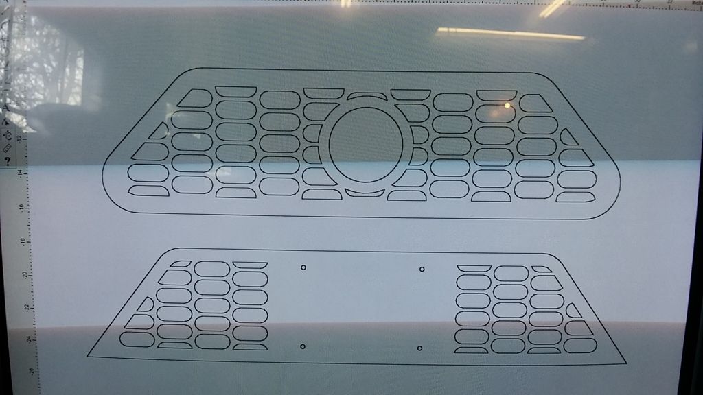
    As I have mentioned in other threads, engine bay cooling requires you to get cool air in from outside and provide a place for the hot air to vent out so you have constant air flow thru the engine bay to keep the temps down. This aids in longevity of the parts in the engine bay...like your transaxle. I recently made the Side Scoop Louvers available here to help get some fresh air into the engine bay. The only way those Side Scoop Louvers can get fresh air in is if there is a place for the existing air in the engine bay to get out. Otherwise, the Side Scoop Louvers are just trying to pressurize the engine bay and you get no flow. These parts would give all of that air a place to escape. Here is a CAD drawing of a couple parts I could offer to you guys.


    The top piece would be for the area between the tail lights. This one would be for the AJW exhaust with a single 3" outlet. The diameter of the hole is 4.25" to provide 5/8" clearance all the way around the 3" exhaust pipe. I could also make this panel without the exhaust trim hole for those of you not using that exhaust. I could also incorporate the license plate mounting holes into this part for those of you planning on mounting your license plate in this area. This piece would bond to the inside of the body....the outer "flange" would not be seen. The hole in the body would be cut undersized so the flange would be hidden behind the body.

    The lower piece would be for the area directly below that. This piece is set up for mounting the license plate with vent holes on both sides. This part is designed to mount to the outside of the body where the flange around outer perimeter would be visible. This could be bonded, bolted or riveted to the body. As with the top piece, the license plate mount could be eliminated and the whole area could be vented.
    Shane Vacek
    VRaptor SpeedWorks, LLC
    www.vraptorspeedworks.com
    Turn-key GTM, SL-C & Ultima GTR Built to Your Specs!
    Offering a full line of GTM Upgrades and Custom Parts

  2. #2
    Mechie3's Avatar
    Join Date
    May 2012
    Location
    Indianapolis
    Posts
    5,174
    Post Thanks / Like
    I like it. I made a template and ordered material to make my own but haven't gotten to a point to put it into CAD yet. I'm making mine to mount different lights too. I like the Hella's you use on the GTM. I was going to try to do a flattened hex pattern.

    It would be cool if you could make it modular for those without the AJW exhaust (don't know how many do/don't have it) so you don't have to stock many different pieces. Aloha 818 and Matteo both used the center upper portion for their license plate vs the lower one. If you were able to make the bottom one completely open you could sell a separate mount (just a flat piece of stock really) and people could bolt or rivet it (or the original FFR license plate mount) to the bottom if they want the plate there or leave it completely open if they wanted the plate up high. Not sure how to make the top one modular.

    Check out Aloha's thread. He mounted his panels underneath with a thin auto edge guard around the fiberglass to give it a finished look. It would work well for these too.
    Zero Decibel Motorsports
    Check out my new website!
    www.zerodecibelmotorsports.com
    www.facebook.com/zero.decibel.motorsports

  3. #3
    Senior Member FFRSpec72's Avatar
    Join Date
    Feb 2011
    Location
    Kirkland, WA
    Posts
    2,255
    Post Thanks / Like
    Looks good, I agree with Mechie3's comments, also wondering if the the pattern is too restrictive, and if louvers would allow more air flow and be better to direct the air to the low pressure area in the rear.

    What about louvers for the top of the rear deck lid, that might also help or were you trying to get the are to exit in one area as to not cause turbulence ?
    Tony Nadalin
    2018 SOVREN Big Bore Champion
    2015 SCCA Oregon Region VP3 Champion
    2012 ICSCC ITE Class Champion
    FFR MkII Challenge Car, Spec Racer, Street Legal, SCCA, ICSCC and NASA Racing
    818R Build in progress

  4. #4
    VRaptor SpeedWorks, LLC's Avatar
    Join Date
    Feb 2011
    Posts
    1,458
    Post Thanks / Like
    Quote Originally Posted by Mechie3 View Post
    I like it. I made a template and ordered material to make my own but haven't gotten to a point to put it into CAD yet. I'm making mine to mount different lights too. I like the Hella's you use on the GTM. I was going to try to do a flattened hex pattern.

    It would be cool if you could make it modular for those without the AJW exhaust (don't know how many do/don't have it) so you don't have to stock many different pieces. Aloha 818 and Matteo both used the center upper portion for their license plate vs the lower one. If you were able to make the bottom one completely open you could sell a separate mount (just a flat piece of stock really) and people could bolt or rivet it (or the original FFR license plate mount) to the bottom if they want the plate there or leave it completely open if they wanted the plate up high. Not sure how to make the top one modular.

    Check out Aloha's thread. He mounted his panels underneath with a thin auto edge guard around the fiberglass to give it a finished look. It would work well for these too.
    Yes, you could use some edge-guard with these if you wanted to. I prefer to just finish out the cut edge nicely....cut inside the line and then sand the edge down exactly to the line and hit the backside of the fiberglass with a DA to take out any high spots and make it a nice, even, smooth thickness. We paint all of our cars here, so if you're not painting your car, I can see the reason to use the edgeguard.....although I probably still wouldn't. I'd just take a sharpie and blacken the raw fiberglass edge.

    As far as making them "universal", I don't really have to worry about that. I don't stock any parts on the shelf....only sheets of aluminum. When the orders come in, I cut the parts and ship them out. So if I had 3 different versions of both the upper and lower piece here, it's no big deal.....I just open the correct drawing and cut the part that was ordered.

    As for the Hella tail lights.....are you talking about the LED ones we used in GTM #12?

    http://vraptorspeedworks.com/2014/vrsw-gtm-12/

    Those are pretty pricey......like in the $800-900 range. Yes, it would be easy enough to make this panel cover that whole area and incorporate new mounting holes for different tail lights. Maybe an option for the future.....
    Shane Vacek
    VRaptor SpeedWorks, LLC
    www.vraptorspeedworks.com
    Turn-key GTM, SL-C & Ultima GTR Built to Your Specs!
    Offering a full line of GTM Upgrades and Custom Parts

  5. #5
    VRaptor SpeedWorks, LLC's Avatar
    Join Date
    Feb 2011
    Posts
    1,458
    Post Thanks / Like
    Quote Originally Posted by FFRSpec72 View Post
    Looks good, I agree with Mechie3's comments, also wondering if the the pattern is too restrictive, and if louvers would allow more air flow and be better to direct the air to the low pressure area in the rear.

    What about louvers for the top of the rear deck lid, that might also help or were you trying to get the are to exit in one area as to not cause turbulence ?
    Hi Tony,

    I think that pattern should flow a pretty good amount of air. Each one of those ovals is 2.3" long and 1" high. Yes, I could try drawing up something in the form of some louvers also for that area. As for louvers for the top of the rear deck lid....I'm still thinking that any heat that comes out of the top deck is going to be sucked forward into the cockpit by the low pressure area behind the windshield......maybe not if the opening was at the very back? Probably no way to know until someone tries it.
    Shane Vacek
    VRaptor SpeedWorks, LLC
    www.vraptorspeedworks.com
    Turn-key GTM, SL-C & Ultima GTR Built to Your Specs!
    Offering a full line of GTM Upgrades and Custom Parts

  6. #6
    Member
    Join Date
    Mar 2013
    Posts
    42
    Post Thanks / Like
    Hasn't anyone done a tuft test on an 818? I am talking about short tufts of yarn taped onto the surface in various area to see which way the air actually is flowing, where are the higher pressures, where are the lower ones...
    We used to do this in the wind tunnel, doing them close to each other but only one side of the car is necessary. This tells a bit about the boundary layer flow as well and is invaluable for locating ducts, etc. I would assume that a goPro camera could be used to record the flow or else you might need a buddy driving along side. The flow at 30-50 mph would be high enough to make the tufts move. The tuft "direction" will be the same at higher speeds anyway.
    I would like to see a series of photos, if anyone does this.

  7. #7
    Senior Member
    Join Date
    Jun 2011
    Posts
    241
    Post Thanks / Like
    as said in another thread:

    i have a magnehelic gauge that i'd be willing to share with anyone close to me so we can do some pressure testing to see where would be most effective to:

    -vent the engine bay
    -draw air for intake
    -find other areas of high/low pressure for inlet/venting purposes


    this is really the best way to figure out what is going on and how to address airflow...

  8. #8
    Member
    Join Date
    Mar 2013
    Posts
    42
    Post Thanks / Like
    Quote Originally Posted by apexanimal View Post
    as said in another thread:

    i have a magnehelic gauge that i'd be willing to share with anyone close to me so we can do some pressure testing to see where would be most effective to:

    -vent the engine bay
    -draw air for intake
    -find other areas of high/low pressure for inlet/venting purposes


    this is really the best way to figure out what is going on and how to address airflow...
    Except you would have to keep moving the gauge around, rerunning test after test. The simple yarn test (or ink drops in a wind tunnel) is a much more time-efficient way to identify the basic flow issues, using your gauge later to quantify the results.

  9. #9
    Mechie3's Avatar
    Join Date
    May 2012
    Location
    Indianapolis
    Posts
    5,174
    Post Thanks / Like
    Even if venting isn't needed, I think it looks cooler. Reminds me of the McLaren P1 rear mesh.
    Zero Decibel Motorsports
    Check out my new website!
    www.zerodecibelmotorsports.com
    www.facebook.com/zero.decibel.motorsports

  10. #10
    Senior Member metros's Avatar
    Join Date
    Jun 2013
    Location
    NoVA
    Posts
    1,064
    Post Thanks / Like
    ^^^Agreed, it looks great. I know I would be interested.

  11. #11
    Senior Member
    Join Date
    Jun 2011
    Posts
    241
    Post Thanks / Like
    Quote Originally Posted by bigAl View Post
    Except you would have to keep moving the gauge around, rerunning test after test. The simple yarn test (or ink drops in a wind tunnel) is a much more time-efficient way to identify the basic flow issues, using your gauge later to quantify the results.
    time efficient, yes, but nearly everyone doesn't have access to a wind tunnel, and having a chase vehicle taking pictures on the road could be dangerous and reading some of the tufts can be misleading...

    furthermore, when finding areas to vent, it is necessary to take pressure readings from underneath panels that isn't realistic to use tufts for...

    not trying to start a fight or anything, just making an offer with what i've got and used...

    :tipofthehat:

  12. #12
    Senior Member FFR-ADV's Avatar
    Join Date
    Oct 2011
    Location
    NH
    Posts
    597
    Post Thanks / Like
    I can't wait to see this on your 818. Mine has the AJW exhaust. I know the new hardtop does not directly impact the rear but I am waiting for the rest of the 818C hardtop to shake out to see what will look best together. Nice work!

  13. #13
    Senior Member Frank818's Avatar
    Join Date
    Jun 2013
    Location
    QC, Canada
    Posts
    5,732
    Post Thanks / Like
    I am into these rear louvers. I will also have a custom full 3" exhaust for which the tip has no place to route yet. Your louvers convinced me. Paper louvers for the time being.
    Frank
    818 chassis #181 powered by a '93 VW VR6 Turbo GT3582R
    Go-karted Aug 5, 2016 - Then May 19+21, 2017
    Tracked May 27/July 26, 2017
    Build time before being driveable on Sep 27, 2019: over 6000h
    Build Completed Winter 2021

  14. #14
    VRaptor SpeedWorks, LLC's Avatar
    Join Date
    Feb 2011
    Posts
    1,458
    Post Thanks / Like
    I'm currently working on a louvered model for this area also. If you like the look of the screenshot above and want to order, shoot me an email. The drawing is the time consuming part. Going from that drawing to cutting can be done in about 5 minutes.

    I'll post some pics of the louvered parts screen shot as soon as I get it done.
    Shane Vacek
    VRaptor SpeedWorks, LLC
    www.vraptorspeedworks.com
    Turn-key GTM, SL-C & Ultima GTR Built to Your Specs!
    Offering a full line of GTM Upgrades and Custom Parts

  15. #15
    Senior Member
    Join Date
    Mar 2011
    Location
    Houston
    Posts
    477
    Post Thanks / Like

    Shield & Duct around the Exhaust?

    I've been following the engine bay heat discussions with interest.

    After some driving yesterday I immediately checked my vents (by hand...really scientific, I know).
    As before, the rear deck vent was really hot....the under-license-plate vent....cool.

    I opened the rear deck and, except for the area around the exhaust down pipe and muffler everything else was relatively cool.

    Possible the exhaust pipe could be shielded by a "duct" with a separate cold air supply and exhaust vent........? Anyone done any work on shielding the exhaust effectively? Especially those with exhausts close to the transmission, might benefit.


    fred

  16. #16
    Senior Member
    Join Date
    Sep 2013
    Location
    Chicago, IL
    Posts
    571
    Post Thanks / Like
    Quote Originally Posted by bigAl View Post
    Hasn't anyone done a tuft test on an 818? I am talking about short tufts of yarn taped onto the surface in various area to see which way the air actually is flowing, where are the higher pressures, where are the lower ones...
    Thank you! I've been wondering why folks with finished cars haven't done this yet too. I was going to pitch the idea to Plavan, since he's in the thick of tackling cooling woes. There are lots of ways to test flow, but good old fashioned yarn is hard to beat for ease and cost.

    I once tried oil drops as well, but the concoction I mixed up was too thick and it dried before I had a chance to get enough flow to move the drops. Hey, you gotta take a swing at low lying fruit when you can.

    Best,
    -j
    "Weight transfer is the enemy."

    Executive Director
    The Community Garage

Posting Permissions

  • You may not post new threads
  • You may not post replies
  • You may not post attachments
  • You may not edit your posts
  •  

FFMetal

Visit our community sponsor