Boig Motorsports

Visit our community sponsor

Thanks Thanks:  0
Likes Likes:  0
Page 2 of 5 FirstFirst 1234 ... LastLast
Results 41 to 80 of 174

Thread: New 818 Configurations Windtunnel Tested

  1. #41
    Director of R&D, FFR Jim Schenck's Avatar
    Join Date
    Mar 2011
    Location
    Wareham
    Posts
    444
    Post Thanks / Like
    Fred,

    The airflow in all the inlets we tested was channeled into brake duct hose and routed to where the intercooler sits in the stock wrx top mount location. The airflow meters are provided by the wind tunnel and are hooked into their data collection system, they are 3 inch diameter which works well for some vents (like the decklid and roof scoop) but may be restrictive on the side vents. Since we were going for relative numbers I think this was ok, but for real world use I was thinking 4 inch duct hose would be better from the side vents. To be most effective the hose would need to be hooked into a box around the duct that allows it to collect the air and then channels it down. That is how ours was arranged into the 3 inch duct as well, albeit fairly crude and made mostly of duct tape.

    I am also picturing a box that sits on top of the intercooler with 4 inlets, 2 three inch and 2 four inch, to force this channeled air through, but we haven't gotten that far yet and we still have to really process the data before we start making any new parts to try. We ran 39 separate tests so there is a lot to look through.
    Jim Schenck
    Factory Five Racing

  2. #42
    Senior Member AZPete's Avatar
    Join Date
    Feb 2011
    Location
    Scottsdale, AZ
    Posts
    2,374
    Post Thanks / Like
    Thanks, Jim!!
    I epoxyed threaded studs around the vents a while ago so now, since you found the vents move air, I'll try making some ducts .
    818S/C : Chassis #25 with 06 WRX 2.5 turbo, ABS, cruise, PS, A/C, Apple CarPlay, rear camera, power windows & locks, leather & other complexities. Sold 10/19 with 5,800 miles.
    Mk3 Roadster #6228 4.6L, T45, IRS, PS, PB, ABS, Cruise, Koni's, 17" Halibrands, red w/ silver - 9K miles then sold @ Barrett-Jackson Jan 2011 (got back cash spent).

  3. #43
    Senior Member Flamshackle's Avatar
    Join Date
    Jun 2011
    Location
    Aotearoa (New Zealand)
    Posts
    648
    Post Thanks / Like
    Quote Originally Posted by Jim Schenck View Post
    Fred,

    The airflow in all the inlets we tested was channeled into brake duct hose and routed to where the intercooler sits in the stock wrx top mount location. The airflow meters are provided by the wind tunnel and are hooked into their data collection system, they are 3 inch diameter which works well for some vents (like the decklid and roof scoop) but may be restrictive on the side vents. Since we were going for relative numbers I think this was ok, but for real world use I was thinking 4 inch duct hose would be better from the side vents. To be most effective the hose would need to be hooked into a box around the duct that allows it to collect the air and then channels it down. That is how ours was arranged into the 3 inch duct as well, albeit fairly crude and made mostly of duct tape.

    I am also picturing a box that sits on top of the intercooler with 4 inlets, 2 three inch and 2 four inch, to force this channeled air through, but we haven't gotten that far yet and we still have to really process the data before we start making any new parts to try. We ran 39 separate tests so there is a lot to look through.
    This information is gold! Will you guys be producing the external air collector box for sale?
    __________________________________________________ _____________

    That man is no fool, who gives what he cannot keep to gain what he cannot lose
    __________________________________________________ _____________

  4. #44
    Senior Member
    Join Date
    Mar 2011
    Location
    Houston
    Posts
    477
    Post Thanks / Like
    Quote Originally Posted by Jim Schenck View Post
    Fred,

    The airflow in all the inlets we tested was channeled into brake duct hose and routed to where the intercooler sits in the stock wrx top mount location. The airflow meters are provided by the wind tunnel and are hooked into their data collection system, they are 3 inch diameter which works well for some vents (like the decklid and roof scoop) but may be restrictive on the side vents. Since we were going for relative numbers I think this was ok, but for real world use I was thinking 4 inch duct hose would be better from the side vents. To be most effective the hose would need to be hooked into a box around the duct that allows it to collect the air and then channels it down. That is how ours was arranged into the 3 inch duct as well, albeit fairly crude and made mostly of duct tape.

    I am also picturing a box that sits on top of the intercooler with 4 inlets, 2 three inch and 2 four inch, to force this channeled air through, but we haven't gotten that far yet and we still have to really process the data before we start making any new parts to try. We ran 39 separate tests so there is a lot to look through.
    Thank you Jim. Wish I were closer geographically...would love to spend time going through "stuff".

    I am selling my #18 this weekend... decision driven by changed domestic circumstances. Its been fun.

    fred

    A question: Wouldn't it make the hose ducting simpler if you totally isolate the inlet side of the Intercooler as I have done. Creating a "plenum" so the hoses could feed into the plenum at any convenient place?
    Last edited by freds; 10-09-2015 at 09:08 AM.

  5. #45
    Senior Member TX-Lou's Avatar
    Join Date
    Jul 2015
    Posts
    119
    Post Thanks / Like
    Quote Originally Posted by Flamshackle View Post
    This information is gold! Will you guys be producing the external air collector box for sale?
    I would like to second that suggestion. If FFR can produce and sell an air collector box for the stock intercooler, plus maybe the inlet boxes that would be great. I'm sure I can put something together but it wouldn't look anywhere near as good and probably wouldn't work as well as something that was professionally produced.

  6. #46
    Senior Member
    Join Date
    Oct 2012
    Posts
    556
    Post Thanks / Like
    I have re-purposed the stock WRX under hood mounted air collector box. I have also improved/sealed the FFR provided air collector channels from the two top scoops. Seems to be working fine. I may add larger scoops to sit on top of the hood openings.

  7. #47
    Senior Member billjr212's Avatar
    Join Date
    Feb 2011
    Location
    Frankfort, IL
    Posts
    734
    Post Thanks / Like
    Quote Originally Posted by tmoretta View Post
    I have also improved/sealed the FFR provided air collector channels from the two top scoops. Seems to be working fine.
    I did this as well, but I think I'm going to start from scratch and try to mock something up that is mounted (or bonded) directly to the engine cover itself.

    Quote Originally Posted by tmoretta View Post
    I have re-purposed the stock WRX under hood mounted air collector box.
    I like the idea of re-purposing the stock WRX under hood mounted air collector box. I may have to look into that as well (assuming I didn't sell it already). Would be nice to have everything mounted to the lid to allow easier access to the engine once the lid is opened.

    Quote Originally Posted by tmoretta View Post
    I may add larger scoops to sit on top of the hood openings.
    I considered this also, but with the soft top, it becomes a tight fit.


    Look forward to seeing the FFR ducting solution if there is one. I won't be re-visiting this part of the project until the snow starts falling in Chicago.

  8. #48
    Director of R&D, FFR Jim Schenck's Avatar
    Join Date
    Mar 2011
    Location
    Wareham
    Posts
    444
    Post Thanks / Like
    We did try adding scoops (from the 65 coupe cowl) that roughly doubled the decklid duct opening, but placing them directly on top of that duct strangely they made the flow worse. We also tried cutting these ducts bigger but the frame gets pretty close if you go back very far and that compromises the shape, with that funky shaped but larger duct the flow was also worse than the stock duct. I am sure that there are things that will improve the flow in these areas but some of the more obvious solutions didn't act how we thought they would.
    Jim Schenck
    Factory Five Racing

  9. #49
    Senior Member Goldwing's Avatar
    Join Date
    Nov 2012
    Location
    Medina, OH
    Posts
    744
    Post Thanks / Like
    Jim, thanks for spending time on this topic. Would a NACA style inlet in front of the cutout help draw more of the airstream into the vent? Creating a low pressure area forward of the cutout to draw the airstream towards the opening, then positive pressure builds in the opening as the air stream rams into the opening. I add that last sentence to specify we aren't lowering pressure at the opening, rather forward of it, if I understand the principle correctly. Both inlet paths for the deck lid and side vents are straight lead ins and may not be pulling the airstream towards the vent opening, thus the airflow concerns.

    I had been planning to isolate the vent air to the A2A intercooler using either both deck lid vents or the left side vent. I'd use the right side vent to feed intake air. Whatever I didn't use for intercooler air was to feed the engine bay in general. With the suggestion to feed 4 vents to the intercooler, will the engine bay at large have enough air to stay cool enough? I had thoughts to isolate the air leaving the intercooler to further behind the engine or to the center deck lid vent. It sounds like the former would be more effective from the testing you mentioned. Again, thanks for taking the time.

    Rich
    Rich

    818S in progress. 2007 WRX sedan donor.
    Powered up: 7-8-14, First Start: 7-20-14, Go kart: 8-19-14

  10. #50
    Tazio Nuvolari wannabe Scargo's Avatar
    Join Date
    Nov 2013
    Location
    south-central CT
    Posts
    1,611
    Post Thanks / Like
    Two 5" and two 4" diameter tubes would equal the 65 square inch area of my 2008 STi hood scoop. Though the side inlets might equal that area I would assume they cannot get the clean direct air the hood scoop does. Still, this is something to ponder. The box the tubes would feed into could have additional air fed from other places. Other scoops could be added. Side inlets could stick out more and increase in area. It could be a porcupine of scoops!
    For my R, my current scheme is to only have a driver's side windshield and a covered passenger side, much like the Lotus 211. This might make the hump on the passenger side more useful as a scoop.

  11. #51
    Director of R&D, FFR Jim Schenck's Avatar
    Join Date
    Mar 2011
    Location
    Wareham
    Posts
    444
    Post Thanks / Like
    Rich,

    The decklid duct has some of this effect from the recessed lead in, it isn't in the shape of a NACA duct and I am sure it isn't as efficient from a drag standpoint. I do agree there are ways out there to get more air into this duct, just a lot of testing involved to find what is the most effective. We did see a somewhat related effect on the roof duct on the 818C, when we taped over the windshield seam to smooth the air ahead of the roof scoop it cut down on airflow through the duct. Just having that little step slowed the air down enough to get more into the duct than without it.

    For engine bay cooling there is definitely airflow under the car that can be tapped into, or what we did on the R is cut the front of the "pontoons" out right behind the front wheels. The thought was not only to get air to the engine bay but to help cool the radiator tubes going through this area as well. We just screened off the front to keep debris out from the front tire. I didn't try any tests on that area in the tunnel because the tires were not spinning, I didn't think the results would be meaningful in that particular area because of that.

    Scargo,

    We did run tests both in the tunnel and on track with no windscreen and just using the dash bump for the instrument cluster as an air diverter over the driver. Even with John saying the airflow around his helmet was smooth and not affecting him, the airflow in the cockpit area was still very turbulent in front of the hump on the passenger side. In the tunnel test both drag and downforce were considerably better with the full windscreen than without it, and in most every test we have done the area directly behind the cockpit has just been a tough place to get any clean airflow. In a lot of tests the air was flowing backward from the engine bay into the cockpit, we saw that with both the smoke at the tunnel and with strands of yarn at the track.
    Jim Schenck
    Factory Five Racing

  12. #52
    Senior Member
    Join Date
    Oct 2013
    Posts
    322
    Post Thanks / Like
    Quote Originally Posted by Jim Schenck View Post
    In a lot of tests the air was flowing backward from the engine bay into the cockpit, we saw that with both the smoke at the tunnel and with strands of yarn at the track.
    Once again Jim thank you so much for sharing these test results. During the yarn testing was the complete car tuffted? Any pictures or video clips?

  13. #53
    Member
    Join Date
    Mar 2013
    Posts
    42
    Post Thanks / Like
    Jim said ".... We did see a somewhat related effect on the roof duct on the 818C, when we taped over the windshield seam to smooth the air ahead of the roof scoop it cut down on airflow through the duct. Just having that little step slowed the air down enough to get more into the duct than without it."

    Probably the windshield seam trips the boundary layer from laminar to turbulent, which has enough more energy to follow the form better.

  14. #54
    Junior Member
    Join Date
    Dec 2012
    Location
    Oregon
    Posts
    20
    Post Thanks / Like
    Quote Originally Posted by bigAl View Post
    Probably the windshield seam trips the boundary layer from laminar to turbulent, which has enough more energy to follow the form better.
    Exactly

    Regarding using a plenum on the intercooler being feed by multiple sources.......
    My day job is working with light aircraft..... Everything from exterior aerodynamics to designing flow paths for cooling air for air cooled engines and other accessories.

    When converting dynamic airflow into static air pressure within a plenum, when the air is from multiple sources , you need to keep in mind that if any of the sources are from a location that would result in a different static pressure if used on their own, the end result could be simply adding an air supply source that would end up having reverse flow or at best, a flow much lower than would be possible if it was used on its own. I.E., all of the air sources have to have similar pressure capability or you will end up with flow moving between them instead of going through the intercooler. Unless you are willing to do pressure measurements at a lot of different locations (at speed), it is safest to stay with one source location, or at a maximum, two, with very similar physical characteristics (such as the scoop on each side). Even then, the way the two sources are connected to the plenum can have an adverse effect on how well it performs. Such as in the case where a lot of flex duct is being used. If there is a lot more (particularly if it has more bends) on one side than the other, one can have a negative interaction on the performance of the other (flex ducting has a lot of inherent flow resistance).

  15. #55
    Director of R&D, FFR Jim Schenck's Avatar
    Join Date
    Mar 2011
    Location
    Wareham
    Posts
    444
    Post Thanks / Like
    Quote Originally Posted by mindinclouds View Post
    Exactly

    Regarding using a plenum on the intercooler being feed by multiple sources.......
    My day job is working with light aircraft..... Everything from exterior aerodynamics to designing flow paths for cooling air for air cooled engines and other accessories.

    When converting dynamic airflow into static air pressure within a plenum, when the air is from multiple sources , you need to keep in mind that if any of the sources are from a location that would result in a different static pressure if used on their own, the end result could be simply adding an air supply source that would end up having reverse flow or at best, a flow much lower than would be possible if it was used on its own. I.E., all of the air sources have to have similar pressure capability or you will end up with flow moving between them instead of going through the intercooler. Unless you are willing to do pressure measurements at a lot of different locations (at speed), it is safest to stay with one source location, or at a maximum, two, with very similar physical characteristics (such as the scoop on each side). Even then, the way the two sources are connected to the plenum can have an adverse effect on how well it performs. Such as in the case where a lot of flex duct is being used. If there is a lot more (particularly if it has more bends) on one side than the other, one can have a negative interaction on the performance of the other (flex ducting has a lot of inherent flow resistance).
    The flow reversal out addition ducts is something we have considered, and agreed best case would be if we could get enough flow from just one symmetrical pair of ducts. From what I have seen of the ducts we have I think we have ok airflow for a stock engine and intercooler using just two decklid vents but for either built engines or extended track use I think we need to have more flow than just one pair will provide. One way we may solve this is to separate the intercooler box into two separate plenums so each pair of vents feed their own area. The challenge here is that we would like this system to fit as many different configurations of intercoolers as possible, stock, STI, bolt in replacement, and oversize replacement, and there is a pretty big range of sizes among those. Also the rear decklid is fairly close to the top of the intercooler so that limits how we can pair the incoming vents as well. What I am picturing is a trim to fit composite box that also has an aluminum divider and likely one wall made from aluminum that can be slid in and out to fit the different size intercoolers. We are still early in the design stage though and I am sure we will be testing other configurations along with that before deciding on what direction we will go.
    Jim Schenck
    Factory Five Racing

  16. #56
    Webmaster, FFR
    Join Date
    Feb 2011
    Location
    Middleboro, MA
    Posts
    1,834
    Post Thanks / Like
    Jim asked me to post this quick video of the 818R at the track.

    Dave Lindsey
    FFR's Mad Dog

  17. #57
    Senior Member Flamshackle's Avatar
    Join Date
    Jun 2011
    Location
    Aotearoa (New Zealand)
    Posts
    648
    Post Thanks / Like
    Quote Originally Posted by Jim Schenck View Post
    The flow reversal out addition ducts is something we have considered, and agreed best case would be if we could get enough flow from just one symmetrical pair of ducts. From what I have seen of the ducts we have I think we have ok airflow for a stock engine and intercooler using just two decklid vents but for either built engines or extended track use I think we need to have more flow than just one pair will provide. One way we may solve this is to separate the intercooler box into two separate plenums so each pair of vents feed their own area. The challenge here is that we would like this system to fit as many different configurations of intercoolers as possible, stock, STI, bolt in replacement, and oversize replacement, and there is a pretty big range of sizes among those. Also the rear decklid is fairly close to the top of the intercooler so that limits how we can pair the incoming vents as well. What I am picturing is a trim to fit composite box that also has an aluminum divider and likely one wall made from aluminum that can be slid in and out to fit the different size intercoolers. We are still early in the design stage though and I am sure we will be testing other configurations along with that before deciding on what direction we will go.
    Jim what about the coupe roof scoop? Are you confident that it will draw enough air to stand alone as a inter cooler feed?
    __________________________________________________ _____________

    That man is no fool, who gives what he cannot keep to gain what he cannot lose
    __________________________________________________ _____________

  18. #58
    Tazio Nuvolari wannabe Scargo's Avatar
    Join Date
    Nov 2013
    Location
    south-central CT
    Posts
    1,611
    Post Thanks / Like
    Jim, I suspected that you were trying for a production fix or something akin to "one size fits all". With our Rs I think that is unnecessary. Yes, there will be the person who does it by the book and perhaps, if there is an 818 class for racing, some mods might be illegal.
    What I am getting to is that I am trying to think "outside the box" that you may be encumbered by. I wonder where else an STi intercooler (or two) might be located?
    I'm not quite to that point yet and it's hard for me to visualize available space and how you would get air to it. I certainly don't see it staying, perched above a hot motor.

  19. #59
    Senior Member
    Join Date
    Jun 2011
    Posts
    241
    Post Thanks / Like
    thoughts about pulling in a crap ton of air from the side windows that are a part of the hard top?

    that's a typical move in mr cars and can provide a lot of air...

  20. #60
    Director of R&D, FFR Jim Schenck's Avatar
    Join Date
    Mar 2011
    Location
    Wareham
    Posts
    444
    Post Thanks / Like
    The scoop on the top pulls in a similar volume of air to the ducts on the decklid, however from that point it is a much easier path to the intercooler. My thought on the roof duct airflow is pretty much the same, good enough for stock engine, but big hp cars will need more than just that. Also the current ducts on the hardtop rear windows do flow a useful amount of air but that is also helpful in keeping the whole engine bay cool which was our intent for those. The windows themselves could be replaced with bigger ducts but they are a good help with reducing the blind spot, particularly on the passenger side, so keeping a decent size window in that area is still important.

    What we are shooting for isn't a complete one size fits all, more of just a better baseline solution. There is still a place for water to air units on the street, and the front mount air to air in our R looks to be very promising for a road course only car, not to mention the rear relocated solutions that others have tried as well. Also important to us is to have good comparison data of the various types all on the same car and have it be a car that is pushing the limit a lot more than the stock one would. That really is what we have been trying to put together all summer with the silver and white 818R and its roughly 475hp engine. We got to the point of collecting data at the track where the tunnel test became almost a necessity to help determine which way to go from here, and now with that test in hand we have some good direction of what we want to try next.
    Jim Schenck
    Factory Five Racing

  21. #61
    Senior Member
    Join Date
    Sep 2013
    Location
    Chicago, IL
    Posts
    571
    Post Thanks / Like
    Quote Originally Posted by mindinclouds View Post
    I.E., all of the air sources have to have similar pressure capability or you will end up with flow moving between them instead of going through the intercooler. ... Even then, the way the two sources are connected to the plenum can have an adverse effect on how well it performs. Such as in the case where a lot of flex duct is being used. If there is a lot more (particularly if it has more bends) on one side than the other, one can have a negative interaction on the performance of the other (flex ducting has a lot of inherent flow resistance).
    This had me worried as well.

    Also, flow in a wind tunnel is straight on and uniform, but on track you can go into an extended sweeper (poss. at a yaw angle) which will "unmatch" a matched set of ducts. What I don't know is if this sort of condition could generate an adverse flow that doesn't correct itself once the airflow is straight. I seem to encounter something like this on my daily commute in which I crest a hill and it initiates a flow pattern through the vents and out the sunroof that persists for a long time.

    Anywho, I really like the idea of a split plenum that can be customized. Slick solution.

    Best,
    -j
    "Weight transfer is the enemy."

    Executive Director
    The Community Garage

  22. #62
    Moonlight Performance
    Hindsight's Avatar
    Join Date
    May 2014
    Location
    Atlanta
    Posts
    3,402
    Post Thanks / Like
    Jim.... slightly related question for you: I think you may be the only people who have started out with a five speed in an 818 and then went to a six speed. Curious to get your opinions on what its like driving the 6 speed vs the 5 speed..... too much shifting or do you like the closer gears? Do you feel the same way about street and track or do you like something different for each?

  23. #63
    Senior Member shinn497's Avatar
    Join Date
    Aug 2011
    Posts
    578
    Post Thanks / Like
    Blog Entries
    1
    Also curious this. And I'm wondering about the weight difference.

  24. #64
    fasterer and furiouser longislandwrx's Avatar
    Join Date
    Aug 2012
    Location
    Long Island
    Posts
    2,540
    Post Thanks / Like
    Blog Entries
    6
    any thoughts on ducting air all the way from the front of the car to the rear? rather than moving the intercooler, just run the ducting all the way back feeding the stock location?
    A well stocked beverage fridge is the key to any successful project.

  25. #65
    Senior Member Mulry's Avatar
    Join Date
    May 2012
    Location
    Dallas
    Posts
    273
    Post Thanks / Like
    Quote Originally Posted by longislandwrx View Post
    any thoughts on ducting air all the way from the front of the car to the rear? rather than moving the intercooler, just run the ducting all the way back feeding the stock location?
    My buddies & I were kicking that idea around last night but there were concerns that the ducting would have to be too large to be practical in this application. It seems like the most efficient solution would be to figure out how to make the existing rear side ducts effective.

  26. #66
    Director of R&D, FFR Jim Schenck's Avatar
    Join Date
    Mar 2011
    Location
    Wareham
    Posts
    444
    Post Thanks / Like
    On the transmission side I would say I prefer the 5 speed for the gear ratio spacing, plus it is 64 lbs. lighter and takes a lot less power to spin. (our blue car was down almost 20hp from that switch) The six speeds don't all have the same gearing and the 2007 was definitely nicer than the 2006. For track use we ended up re-gearing our 2006 to give it closer gear spacing in 5th and 6th as we were hitting a wall as soon as we shifted at about 120mph. The six speed does handle a ton more torque though.

    Back to the aero stuff, we have kicked around the idea of ducting from the front on the 818R, but it isn't something we tried. I think you could go through the doors on an R with some decent size ducts but it gets tight when you get up around the front tire, on an S I am not sure where you would route the ducting. Our biggest concern was the length and winding path of the duct would limit the flow too much to be any better, but hard to say for sure without trying it. I would say the ducts would have to be as big as you could fit, maybe something like a 5 inch tube from front to back.
    Jim Schenck
    Factory Five Racing

  27. #67
    Director of R&D, FFR Jim Schenck's Avatar
    Join Date
    Mar 2011
    Location
    Wareham
    Posts
    444
    Post Thanks / Like
    Rintercoolersmall.jpg

    This is how we plumbed the intercooler up to the front, but it was still fairly tight with 2-1/2 inch tubing.
    Jim Schenck
    Factory Five Racing

  28. #68
    Moonlight Performance
    Hindsight's Avatar
    Join Date
    May 2014
    Location
    Atlanta
    Posts
    3,402
    Post Thanks / Like
    Thanks for the transmission info Jim. That's very interesting on the parasitic losses through the 6 speed.

  29. #69
    Junior Member
    Join Date
    Nov 2014
    Posts
    19
    Post Thanks / Like
    Fantastic information, Jim. Can you use SolidWorks CFD for some of this aerodynamic analysis? I could understand you might not be able to examine the whole car. But for evaluating various scoop and duct configurations, it would seem to be a great first-pass tool that would allow many ideas to be evaluated relatively quickly. Now that you have real-world data from a wind tunnel, you have something to calibrate your analysis results against, right? Either way, I'm really glad to see FF sharing so much information about the development process. Thank you.

  30. #70
    Senior Member
    Join Date
    Jun 2013
    Location
    Bowling Green, KY
    Posts
    1,382
    Post Thanks / Like
    Thanks Jim for the info

  31. #71
    Senior Member Rasmus's Avatar
    Join Date
    Mar 2012
    Location
    Las Vegas, USA
    Posts
    983
    Post Thanks / Like
    Jim and Dave,

    Thank you for being so open about this. Lovely to see and read all the new information.


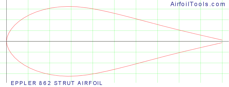
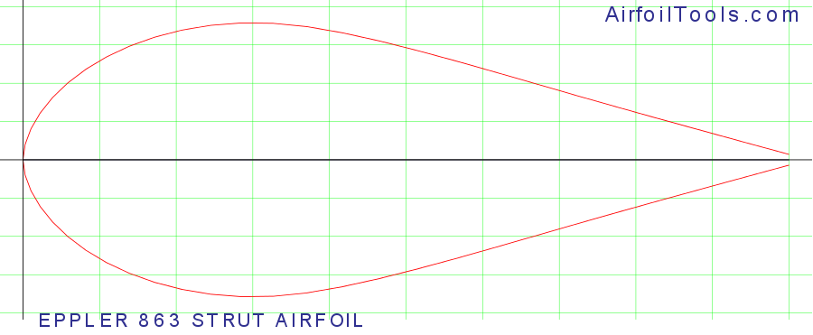
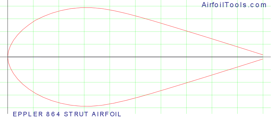
    Jim, regarding the R and the turbulent flow hitting the rear wing: It looks like the rear roll hoop is causing a bunch of turbulence. Round bars do that. I know you already know that though. So two solutions that I can see. 1. move the rear wing up into clean air. or 2. Put a low drag airfoil around the roll bar so you don't get that nasty turbulence in the first place. Make a sandwich out of fiberglass and install it around the bar.

    If you go with the airfoil look into the EPPLER 862, EPPLER 863, or EPPLER 864,


    cd at 0 AoA = 0.02828. That's super low.

    cd at 0 AoA = 0.03459

    cd at 0 AoA = 0.04195

    Ultra-low drag as long as it's mostly set at 0 angle of attack. By comparison a circle has a cd (coefficient of drag) of 1.17
    Last edited by Rasmus; 10-16-2015 at 08:33 PM.
    Fast Cars, Fast Women, Fast Haircuts!

  32. #72
    Director of R&D, FFR Jim Schenck's Avatar
    Join Date
    Mar 2011
    Location
    Wareham
    Posts
    444
    Post Thanks / Like
    The video doesn't show much of it but we spent a good amount of time with the R and the smoke wand looking at the flow around the bar and how it was affecting the wing. We didn't see as much of a difference as we were expecting between the straight wings we tested and the curved APR that we offer and is on the the GTMs and was on the Blue car. I think the airflow from the cage is the reason for this, you could clearly see that the section of wing sticking out further than the width of the main hoop had much better flow than the area behind the bar, and in the curved wing this is also where the shape is more designed to be pulling airflow from a different direction as it comes off the roof or the humps in the decklid. I feel like the best solution functionally would be to raise the wing above the bar, but since we have to use this car as a demo and a show car it has prevented us from doing that. (lets just say we all aren't quite in agreement on that one)

    On another car, a modified challenge car, we once made an airfoil around the cage for a track test. The goal in that case was to produce downforce from a part of the car where we already had to have the drag penalty. The result was a car that was undrivable, not from a handling standpoint but because the low pressure under the airfoil was trying to pull the drivers helmet off. Not exactly the same as you are describing but good to know if you try something similar.
    Jim Schenck
    Factory Five Racing

  33. #73
    Senior Member Mulry's Avatar
    Join Date
    May 2012
    Location
    Dallas
    Posts
    273
    Post Thanks / Like
    Quote Originally Posted by Jim Schenck View Post
    The result was a car that was undrivable, not from a handling standpoint but because the low pressure under the airfoil was trying to pull the drivers helmet off. Not exactly the same as you are describing but good to know if you try something similar.
    That had to have been somewhat disconcerting for that driver.

  34. #74
    Senior Member Rasmus's Avatar
    Join Date
    Mar 2012
    Location
    Las Vegas, USA
    Posts
    983
    Post Thanks / Like
    Quote Originally Posted by Jim Schenck View Post
    On another car, a modified challenge car, we once made an airfoil around the cage for a track test. The goal in that case was to produce downforce from a part of the car where we already had to have the drag penalty. The result was a car that was undrivable, not from a handling standpoint but because the low pressure under the airfoil was trying to pull the drivers helmet off. Not exactly the same as you are describing but good to know if you try something similar.
    That's hilarious! Not for the person or people that put into all the work making a custom airfoil to fit around a roll bar at the time. But in retrospect. Hilarious!

    Also good to know about the effect a pressure differential airfoil right near the drivers helmet would have. Because, in my dreams, I was thinking about doing that. Now I'll probably just go with a no-lift, low drag, laminar flow, airfoil like I linked above.
    Fast Cars, Fast Women, Fast Haircuts!

  35. #75
    Sgt.Gator's Avatar
    Join Date
    Apr 2013
    Location
    Bend, Oregon
    Posts
    1,652
    Post Thanks / Like
    Regarding turning the roll bar into an airfoil, almost all the class rules I've read make it illegal to have a wing forward of the rear wheels, or more than one wing. You could argue with the tech inspector that it's not a wing, but would probably lose the argument. They aren't going to care if it has zero downforce or not.

    There's probably some super-unlimited classes where it could be done, but that's an expensive way to race.
    "Good Judgement comes from Experience. Experience comes from Bad Judgement"
    Owner: Colonel Red Racing
    eBAy Store: http://stores.ebay.com/colonelredracing
    818R ICSCC SPM
    2005 Subaru STI Race Car ICSCC ST and SPM
    Palatov DP4 - ICSCC Sports Racer

  36. #76
    Senior Member Canadian818's Avatar
    Join Date
    Nov 2011
    Location
    Edmonton, Alberta
    Posts
    1,378
    Post Thanks / Like
    Quote Originally Posted by Sgt.Gator View Post
    Regarding turning the roll bar into an airfoil, almost all the class rules I've read make it illegal to have a wing forward of the rear wheels, or more than one wing. You could argue with the tech inspector that it's not a wing, but would probably lose the argument. They aren't going to care if it has zero downforce or not.

    There's probably some super-unlimited classes where it could be done, but that's an expensive way to race.
    This will solve everything, lol

    Adam _____ Instagram @PopesProjects____ YouTube Channel
    818 SRX - #91
    Arrived 01/02/2014
    First Start 10/31/2016
    First Drive 05/22/2017
    Registered 10/25/2019 BRAP818

  37. #77
    Senior Member Frank818's Avatar
    Join Date
    Jun 2013
    Location
    QC, Canada
    Posts
    5,732
    Post Thanks / Like
    How funny! But I think if you need such front upper spoiler it means you have an aero design issue to begin with!
    Nice, the exhaust is in front of front right wheel.
    Frank
    818 chassis #181 powered by a '93 VW VR6 Turbo GT3582R
    Go-karted Aug 5, 2016 - Then May 19+21, 2017
    Tracked May 27/July 26, 2017
    Build time before being driveable on Sep 27, 2019: over 6000h
    Build Completed Winter 2021

  38. #78
    Mechie3's Avatar
    Join Date
    May 2012
    Location
    Indianapolis
    Posts
    5,174
    Post Thanks / Like
    That scion set a track record.
    Zero Decibel Motorsports
    Check out my new website!
    www.zerodecibelmotorsports.com
    www.facebook.com/zero.decibel.motorsports

  39. #79
    Tazio Nuvolari wannabe Scargo's Avatar
    Join Date
    Nov 2013
    Location
    south-central CT
    Posts
    1,611
    Post Thanks / Like
    And tires lasted five laps (just guessing)...

  40. #80
    Senior Member
    Join Date
    Sep 2013
    Location
    Chicago, IL
    Posts
    571
    Post Thanks / Like
    Yeah, that Scion is not a series of mistakes...it's a very well-funded, very fast, serious machine. They've just elected to approach thinking about how to reach their goals in a different way than most folks do. I saw it run once and was just amazed at its speed.

    On the matter of a the roll-bar, if you try to "wing-it" (yuk-yuk-yuk), then you might run afoul of the tech inspectors. But that's not the proposal Rasmus (and I) are suggesting. I'm going to build a fairing around it so that it extends into the body. This is no different than what you see on a Radical (or Honda del Sol). The objective is to simply clean up the body and stop the turbulence and you don't need an airfoil to do that - just about any simple ovoid shape is going to greatly diminish turbulence.

    I did some basic CFD tests a while back on different fairing shapes and was pretty surprised by the difference anything 5:1 and larger makes - just so long as you're not simply hanging a tail on the backside of the tube. SolidWorks is great for this, but you need the Flow Simulation add in...

    Best,
    -j
    Last edited by Santiago; 10-19-2015 at 08:18 AM.
    "Weight transfer is the enemy."

    Executive Director
    The Community Garage

Page 2 of 5 FirstFirst 1234 ... LastLast

Posting Permissions

  • You may not post new threads
  • You may not post replies
  • You may not post attachments
  • You may not edit your posts
  •  

Breeze

Visit our community sponsor