Very Cool Parts

Visit our community sponsor

Thanks Thanks:  0
Likes Likes:  0
Results 1 to 9 of 9

Thread: alternator wire in RF harness

  1. #1
    Senior Member chopthebass's Avatar
    Join Date
    Oct 2013
    Location
    Calgary, Canada
    Posts
    941
    Post Thanks / Like

    alternator wire in RF harness

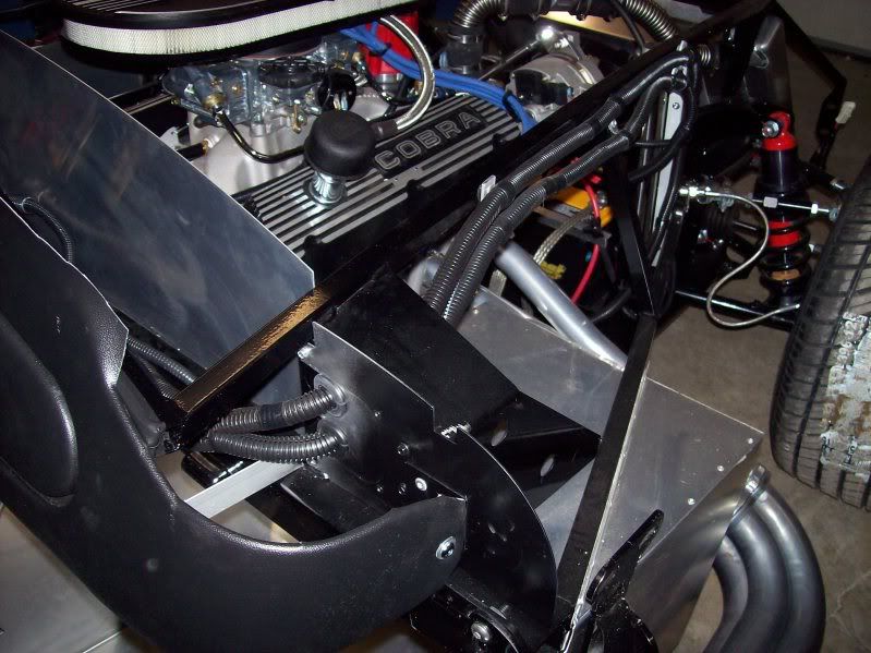
    I have been following the manual to the tee, and now I have come to wiring I have hit a problem. It says fit the alternator wires through the hole in the drivers foot wall. Found the hole (semi-circular), but there's no way the plugs will push through. The surrounding aluminum is rivetted and siliconed. Is there an easy solution other than drill the rivets so I can create a gap?
    Finally started my build the beginning July. 2015!

  2. #2
    Senior Member christenfreedman's Avatar
    Join Date
    Nov 2013
    Posts
    100
    Post Thanks / Like
    I would start to drill out the rivets...You may also need to enlarge the hole to get the other through there as well...

  3. #3
    Senior Member edwardb's Avatar
    Join Date
    Feb 2011
    Location
    Lake Orion, Michigan
    Posts
    10,578
    Post Thanks / Like
    Sounds like you're talking about the hole at the top of the inside driver's footbox wall, near the center, right against the 2 inch square tube. Near your right knee as sitting in the driver's seat. The right one? I've found those to be too small even for just the wires, and needed to be enlarged a bit. As I recall, it only has to be slightly larger then the wires and then the connector(s) in question will just fit through if turned sideways as you push them through. The kit provides some plastic edging to be used on that hole. I've found that a piece of split rubber tubing works a little better and nearly fills the opening. A little black silicone or whatever can finish sealing if needed.
    Build 1: Mk3 Roadster #5125. Sold 11/08/2014. Build 2: Mk4 Roadster #7750. Sold 04/10/2017. Build Thread
    Build 3: Mk4 Roadster 20th Anniversary #8674. Sold 09/07/2020. Build Thread and Video. Build 4: Gen 3 Type 65 Coupe #59. Gen 3 Coyote. Legal 03/04/2020. Build Thread and Video
    Build 5: 35 Hot Rod Truck #138. LS3 and 4L65E auto. Rcvd 01/05/2021. Legal 04/20/2023. Build Thread. Sold 11/9/2023.

  4. #4
    Senior Member rmiller64's Avatar
    Join Date
    Aug 2014
    Location
    Ferndale, WA
    Posts
    337
    Post Thanks / Like
    As Edward said I also enlarged the hole after all sheet metal had been installed. A carbide Burr Bit like the one below on a die grinder or high speed drill will make quick work of reshaping the hole for the size needed. I ran some extra wires through that hole so made mine a bit larger and bought edging material to protect the wire loom.

    19D899_AW01.jpg
    Rick
    #8442 MK4 Complete kit, 331 Stroker, T5, 3.73 Posi 3-Link, 15", Goodyear Billboards
    Order 8/22/14 Del 11/7/14 First Start 3/9/15 Go Cart 3/14/15 Paint 2/25/16
    http://thefactoryfiveforum.com/showt...MK4-8442-Build

  5. #5
    Not a waxer Jeff Kleiner's Avatar
    Join Date
    Feb 2011
    Location
    Bloomington, Indiana
    Posts
    8,095
    Post Thanks / Like
    Personally I don't care for their suggestion to take those big wads of wires out at the hole by the driver's knee. The only thing I run there is the leg of the harness that goes to the rear. I like to run the starter and alternator wires behind the dash then out through the PS firewall extension and forward along the 3/4" tubes. If you secure them on the backside of the tubing like so they are unseen when looking into the engine bay.


    To me this keeps the engine compartment neater and less cluttered. Note that you will need to extend the alternator wires slightly (if you use anything other than a 2G alternator you'll be modifying them anyway).

    Jeff

  6. #6
    Senior Member chopthebass's Avatar
    Join Date
    Oct 2013
    Location
    Calgary, Canada
    Posts
    941
    Post Thanks / Like
    Thanks Jeff. I prefer that idea. In fact I was just wondering where to route the rear harness. The build video glances very quickly at it and wasn't much help. So are rubber grommets included? Doesn't appear to be any in RF kit. Not sure what a 2G alternator is.
    Finally started my build the beginning July. 2015!

  7. #7
    Not a waxer Jeff Kleiner's Avatar
    Join Date
    Feb 2011
    Location
    Bloomington, Indiana
    Posts
    8,095
    Post Thanks / Like
    Quote Originally Posted by chopthebass View Post
    ...So are rubber grommets included? Doesn't appear to be any in RF kit. Not sure what a 2G alternator is.
    Grommets, additional split loom and clamps are all hardware store items. A 2G alternator was the Ford OEM unit from the early 1980s up through the mid '90s and is what the RonFrancis harness is set up to "plug & play". Using something different such as a later 3G, one wire, etc. requires reconfiguration of the harness.

    Jeff

  8. #8
    Senior Member chopthebass's Avatar
    Join Date
    Oct 2013
    Location
    Calgary, Canada
    Posts
    941
    Post Thanks / Like
    Jeff, my alternator has the same 3 pin socket to match the RF harness, so thats good. What are the two thick red wires? Sorry I am crap at electrics.
    Finally started my build the beginning July. 2015!

  9. #9
    Senior Member smithbks's Avatar
    Join Date
    Mar 2014
    Location
    Atlee, VA
    Posts
    152
    Post Thanks / Like
    If I recall correctly those two wires are the same...meaning it is one wire run back to the harness and about 12 inches back from the plug they mate the other red wire to it. If you peel back the loom a little you will see it.
    Mk4 #8340, 351w/427, 3-link, Wilwood 4 piston rear brakes, 3.27 gear, TKO600, delivered June 18th, 2014

Posting Permissions

  • You may not post new threads
  • You may not post replies
  • You may not post attachments
  • You may not edit your posts
  •  

FFMetal

Visit our community sponsor