
Visit our community sponsor

Thanks:
0

Likes:
0
-
Today I installed the accelerator pedal from the donor car. I was not at all happy with the fit. The pedal is on an angle and is much closer to the firewall than the clutch and brake pedals.
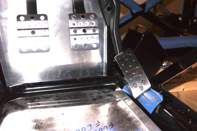
I probably can live with the angle, but I will have to fix the pedal height. The pedal bracket has a pedal stop that keeps it from moving away from the firewall. 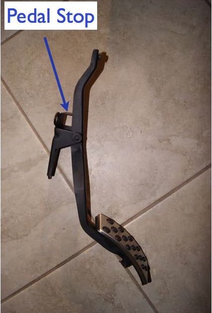
Tomorrow I will trim about 1/2" off the pedal stop and see what that does for it. I will have to think about the angle.
-
Senior Member


Originally Posted by
Gene

Today I installed the accelerator pedal from the donor car. I was not at all happy with the fit. The pedal is on an angle and is much closer to the firewall than the clutch and brake pedals.
I probably can live with the angle, but I will have to fix the pedal height. The pedal bracket has a pedal stop that keeps it from moving away from the firewall.
Tomorrow I will trim about 1/2" off the pedal stop and see what that does for it. I will have to think about the angle.
That's really not very nice. I don't think you would be happy with that once you start driving, and it wouldn't be easy to adjust or replace once the build is finished. I know you're trying to do a donor build. But you would not be disappointed with this pedal. I've used them a couple times. http://www.breezeautomotive.com/details.php?prod_id=283. This will fix the angle and get the pedal up where it belongs. Works great.
Last edited by edwardb; 02-11-2016 at 07:57 AM.
Build 1: Mk3 Roadster #5125. Sold 11/08/2014.
Build 2: Mk4 Roadster #7750. Sold 04/10/2017.
Build Thread
Build 3: Mk4 Roadster 20th Anniversary #8674. Sold 09/07/2020.
Build Thread and
Video.
Build 4: Gen 3 Type 65 Coupe #59. Gen 3 Coyote. Legal 03/04/2020.
Build Thread and
Video
Build 5: 35 Hot Rod Truck #138. LS3 and 4L65E auto. Rcvd 01/05/2021. Legal 04/20/2023.
Build Thread. Sold 11/9/2023.
-
Senior Member

Double check the instructions, that's not right. My donor pedal is modified as prescribed and it does not have so much angle to it.
-
Not a waxer

X2 what edwardb said. When I built my first car and looked at the cheesed up way that the donor pedal was supposed to be used I actually laughed out loud! It's no secret that I'm often not a big fan of upgrading without a proven benefit---the Russ Thompson pedal is definitely proven. When installing it once you have it in your preferred position (usually about 2" forward of the brake pedal when at rest) be sure to make and use a positive pedal stop so that the pedal itself can't travel farther than the throttle plate allows.
Cheers,
Jeff
Cheers,
Jeff
-
I didn't mention in my last post that I did mock up the pedal the way the manual says. It looked like the accelerator pedal was more than 4" ahead of the brake pedal. I just wasn't comfortable with that set up. I think I will go with the Russ Thompson pedal.
Thanks again guys.
-
Since I had a viable alternative with the Russ Thompson pedal, I decided to try making the modifications to the gas pedal in the manual. I really didn't like it. I will go with the alternative.
-
It's been a week since I updated this post. Since then a lot has happened.
I discovered that the fuel tank from my donor car was filled with rust. It was too bad to try to save it or the fuel pump. I got a new tank from Oreilly's and a new fuel pump and bypass pressure regulator from summit. The fuel pump flows 155 liters per hour which is enough for a 500 hp engine. Since mine will only be 300 to 345 hp, it's a little overkill but that's ok.
I also test fitted the steering rack extensions in the donor car steering rack. They stuck. The threads on the rack were galled and they ruined the threads on the steering rack extensions. So, I got a remanufactured steering rack and I am now waiting for new extensions from FFR.
While I was waiting for new parts, I started on the cockpit sheet metal. I've finished the passenger side foot box and most of the rear of the cockpit.
I do have a question. I want to be able to access the pedals, so I'm planning to use rivnuts on the top of the driver side footbox. Is it worth while to use rivnuts on the top half of the inside wall?
Also are there any other places I should use rivets?
-
Senior Member
Originally Posted by
Gene
I do have a question. I want to be able to access the pedals, so I'm planning to use rivnuts on the top of the driver side footbox. Is it worth while to use rivnuts on the top half of the inside wall?
Also are there any other places I should use rivets?
In my opinion, the access cover provided for the inside top DS footbox provides adequate accessibility to the footbox area. There's a lot packed in there, and it's never going to be particularly easy. But between the cover and the what you can reach from inside the cockpit, should be OK. With the body on, you'll find much of the inside top DS footbox is covered anyway, and the top joint is right against the underside of the body. So having it removable wouldn't be easy or help much. Same with the inside panel. The engine will cover much of that or at the very least make it hard to get in and out. Plus you want all those panels nice and sealed for heat, sound, fumes, etc. Having them removable could affect that.
Last edited by edwardb; 02-22-2016 at 08:10 AM.
Build 1: Mk3 Roadster #5125. Sold 11/08/2014.
Build 2: Mk4 Roadster #7750. Sold 04/10/2017.
Build Thread
Build 3: Mk4 Roadster 20th Anniversary #8674. Sold 09/07/2020.
Build Thread and
Video.
Build 4: Gen 3 Type 65 Coupe #59. Gen 3 Coyote. Legal 03/04/2020.
Build Thread and
Video
Build 5: 35 Hot Rod Truck #138. LS3 and 4L65E auto. Rcvd 01/05/2021. Legal 04/20/2023.
Build Thread. Sold 11/9/2023.
-
-
-
It has been a long week with not much done on the roadster. I had to cut up a 20 ft. Long 13 in. Dia tree branch that broke off a tree in my back yard. That initiated a lot of other yard wok that kept me away from the car. The to top off the week my 2009 Prius wouldn't shut off. I took it to the dealer and found out that Toyota has an extended warranty for this problem. So now I'm driving a loaner.
I did manage to finish the installing the brake lines. The factory five roadster build video and some excellent pictures on David Hodgkin's build thread helped a lot.
I am on my iPad now and can't figure how to copy the picture links. I will post the pics when I get home.
-
-
-
Today, in spite of being lazy and wasting half the day watching NASCAR, I did get some work done. I Installed the fuel filter, fuel pump and rubber hose from the pump to the filter.
However, I ran into a mental block about doing the hard lines. The kit comes with 2 sets of 60 inch hard lines for the fuel and return lines. With the position of my fuel filter, I think I need one 60 inch and one 12 inch line. This is so far from what comes in the kit that I was afraid to attach the hard lines.
-
I almost had the same problem with the wire harness. I have the Ron Francis wire harness. After reading the manual, it took me forever to be confident that I was putting the fuse box and main harness in the right place. Finally I just did it. When the wires for the brake switch were the right length and easily installed, I got my confidence back.

-
-
-
-
Gene - where did you find the 4" Seals-it Grommet? I looked at Summit and could only find smaller ones. Thanks!
-
Jazzman,
Sorry for the late replay. I haven't had time to look at the forum for a few days.
I got the grommet at summit. here is a link.
https://www.summitracing.com/parts/sit-gs404-bl
-
I'm at that point in the build where I need to finish the engine and transmission.
Last week I tore down and inspected the engine. Everything looked good, so I put it back together. I still need to find alternator and power steering brackets and order the MSD box and distributor. Other than that it's ready to put on the test stand for the final check.
This weekend was the Goodguys show in Del Mar. It came at a perfect time for me because I need to purchase the rest of the drivetrain.
Yesterday I spent about two hours with Alan Brown from 1 Shop Auto. They are a distributer for Tremec, McLeod and others. He took the time to explain my options and the cost and benefit of each. I decided to go with the TKO 600 with o.68 fifth gear. I decided to go with a hydraulic clutch. I chose a McLeod 1406-30 hydraulic throwout bearing. In spite of the fact that they were a lot more expensive, I decided to go with the McLeod 6913-07 twin clutch kit and a QuickTime RM-6060 bellhousing. 1 Shop’s prices were actually better than Summit’s.
Once part selection was completed, that left the issue of the shortened pedal because of the frame interference with the Wilwood pedal box. The McLeod throwout bearing calls for a 0.75” master cylinder with 1” stroke on a 6:1 pedal. When I measured the stroke I will get without modifying the frame or pedal last night, I had only 0.86” stroke. I did the math myself and calculated that with a 13/16” bore master cylinder I would get 0.85” of stroke. Just enough.
Fortunately, the Wilwood booth was one booth away from the 1 Shop booth. Today, Alan from 1 Shop and I went over to the Wilwood and they recommended a compact remote flange mount master cylinder with a 7/8” bore, a remote reservoir and flex/hard line. This combo will provide full clutch function with 0.75” stroke.
The funny part of all these hydraulic calculations is that two weeks ago I was helping my granddaughter prepare for an 8th grade science test. It was on hydraulics. I had to explain how to do exactly these calculations.
-
-
-
-
Not a waxer
Gene,
When the body is on that master cylinder will be virtually inaccessible. Additionally I'm afraid you'll find it necessary to modify the footbox top and have some challenges with getting it to seal with your brake lines coming out in that location. Sorry to be the bearer of bad news but you might want to consider and address these things now rather than later.
Good luck,
Jeff
Last edited by Jeff Kleiner; 04-13-2016 at 05:13 AM.
-
Jeff,
I have been tied up with a lot of external issues. Family issues and other distractions so I haven't been back to check the forum lately. However, at Huntington Beach, I saw exactly what you were talking about. It helps to see a finished car to understand what you are doing.
Thank you for pointing it out. I really appreciate the input.
-
It's hard to believe that it's been over month since I last updated the post. I spent way too much time building the engine test stand.
I welded up plates to attach to the engine motor mounts.
Then while it was on the engine motor mounts and supported with wood blocks at the rear, I attached the bellhousing and and cheated it's alignment. The initial readings were not good. The bellhousing was 0.013" eccentric to the crankshaft. When I removed it to identify the problem, I saw some powder coat in the pilot hole was effecting the fit. I cleaned up all the holes and reattached and remeasured. This time without the flywheel the eccentricity was 0.003". With the flywheel on it was concentric within 0.0035".
-
-
Finally, after spending way too much time building the test stand, I started the engine. I adjusted the timing, carb float levels and high idle. However, while it runs fine at idle and with gradual increases and decreases in RPM, it backfires through the carb when I give it a quick kick with the accelerator. I have checked for vacuum leaks but can't find any. The initial timing is at 15 degrees and total timing is at 38 degrees without the vacuum advance attached. It backfires both with and without the vacuum advance attached. I am stumped.
I give up for today. I will go play some golf and try again tomorrow.
If anybody has any ideas, I would appreciate the advice and I won't wait a month before I get back to the forum.
-
PLATNUM Supporting Member


IMO you have too much timing in it. Total timing with Vac adv hooked up should only be 34-36 IMO. Base around 8-10. Sounds like it may have a lean spot causing the backfire too. Check accel pump for proper operation.
-
Wallace,
Thanks for the feedback. My engine is a Ford racing crate motor M-6007-XE3M purchased in 2006. When I googled timing for that part number, I got Ford Racing Performance M-6007-X302 340 hp Crate Engine Guide. That document states "Timing: 14 to 16 degrees initial, 36 to 38 total with carburetor". I am running a Holley Street Avenger 570. Since the M-6007-X302 replaced the M-6007-XE3M, I assumed that the timing should be the same.
I will try backing off the timing to see if that helps. I will also start to look into the carb to see what I can find.
Thanks again.
-
I tried to back off the timing to 8 degrees but the backfire continued. I then returned the timing to 15 degrees.
When I checked the vacuum level initially, I did it before I dialed in the idle. At that time the idle was at at about 1200 rpm and the vacuum was at 13". When I dialed in the idle I didn't recheck the vacuum level. Now the idle is at about 800 rpm and the vacuum has dropped to 9". Based on that, the 6.5 power valve that came with the carb was too much. Today, I changed the power valve to 4.5. I also tried to dial in the idle mixture screws but they were just about right initially.
Nothing worked. It still backfires.
-
I just talked to Tom at Ford Racing Performance. He explained that that with this engine at 850 to 900 RPM idle I should have 13" of vacuum. When I told him I had 8", he said that I have a vacuum leak. He explained that the only intake manifold gasket I can use with my performer RPM intake manifold is a few pro 1262R or 1262S-3. He also recommended I use an 1/8" cardboard gasket between the carb and the manifold and coat the gasket with lithium grease. He said initial timing should be between 14 and 18 degrees, with total timing at 34 degrees. Finally he recommended that I disconnect and plug the vacuum advance and run mechanical advance only.
I am now off to see if these recommendations work.
-
Well, I now know that if you have GT-40 heads and an Edelbrock Performer RPM Air Gap intake manifold, you can't use the standard Edelbrock manifold gaskets. I put in a Fel-Pro 1262R manifold gasket and the engine runs fine. No Backfires, good vacuum and a nice idle. Thank you Ford Racing Performance.
-
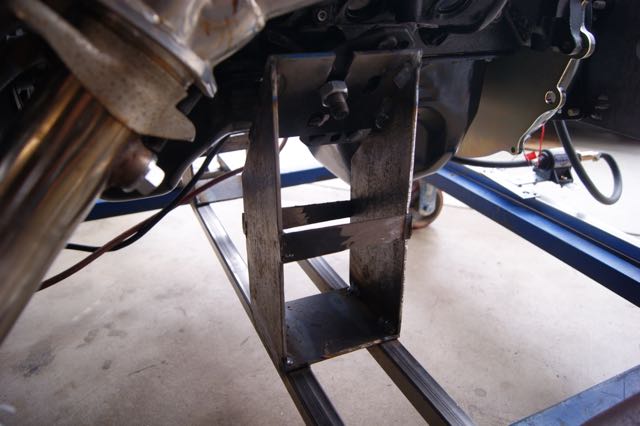
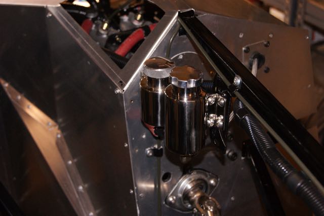
I fabricated a prototype bracket for the clutch reservoir out of a 3/32 steel bracket. In this location I might even be able to fill it.
I will have to make a less amateurish version before I finish the footbox aluminum.

-
-
Yesterday my son came over for father's day and to help me put the engine and transmission in the roadster. To get ready, I tried to put the trans on the engine by myself. I could get the splines engaged but couldn't get the pilot into the pilot bearing. After an hour of trying, I decided to remove the bellhousing and clutch and try when I could look at the pilot as it went into the bearing. That worked OK and with four cut off bolts as guide pins the alignment was good but the fit was still tight.
I put the clutch and bellhousing back on and tried again. By this time my son had arrived and the two of us ran into the same problem, the trans would go on as far as the pilot bearing but we couldn't get it to go all the way on.
Many years ago I learned the hard way never to force things together using mounting bolts. However, I was desperate. I removed the guide bolts and inserted the real bolts. Then slowly, I tightened one bolt one turn with a short wrench. Then moved on to the next bolt, one turn with very little torque. Amazingly it worked. I was able to inch the trans onto the engine.
Once that was done, with the help of my neighbor and his son. we put the engine into the car.
It's starting to look alike a car.

-
When we put the engine in the car, we were careful to make sure that the engine didn't hit the frame or hang up on any chassis parts. Unfortunately, we didn't watch where it came close to the wiring. Eventually we noticed that the motor mount stud was caught on the front wire harness. The wire harness stretched but didn't break.
After replacing a couple of clamps and adding some electrical tape where the loom was spread, the harness was good as new.

-
-
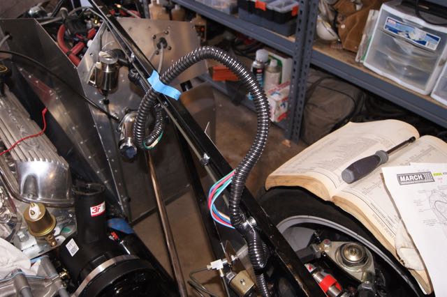
Today, I filled the trans with fluid and made the final routing for the clutch fluid hose. To prevent chafing on the edge of the bell housing, I put wire loom over the fill hose and bleed line.

 Posting Permissions
- You may not post new threads
- You may not post replies
- You may not post attachments
- You may not edit your posts
-
Forum Rules

Visit our community sponsor


 Reply With Quote