
Visit our community sponsor

Thanks:
0

Likes:
0
-
Senior Member

-
Senior Member
-
Senior Member

I believe D is the heater core line - I believe from the water pump. This can not be blocked off as it is required for coolant flow during engine warm up - the kit includes a "U" tube to loop this connection - check the assembly manual.
Can't tell from the angle but is E also coming from the coolant crossover pipe? If so, (if I remember correctly) this feeds the throttle body for cold weather running.
K & L would be the throttle body coolant loop, which you can block off assuming you're not worried about cold weather running/throttle body freezing/emissions issues (I think most of the builds have removed this loop, I have).
Last edited by mikeb75; 10-22-2016 at 07:40 PM.
818SC chassis #206 EJ207 2.0L VF37 twin scroll || Cusco type RS 1.5 LSD || Wilwood pedal box (firewall attach) || Wilwood superlite front calipers
BUILD Phase 1: 6/6/2014 car delivered || 5/24/2015 first start || 6/7/2015 go karted || 4/20/2016 hard-top-topped || 10/25/2016 registered || 11/18/2016 inspected & complete
BUILD Phase 2: 3/8/2017 EJ207v8 || 5/29/2017 re-first re-start || 7/17/2017 re-assembled with race car bits
-
Senior Member
Turbo : the OEM turbo you indicated (M) the hard oil feed line that originates on the engine block using a banjo fitting. It looks like your aftermarket turbo uses a different type of line... on the Blouch site there is a selection for type of oil feed line (STI or WRX block). I believe you should have a stainless steel braided line that has a banjo fitting (for the engine block) and whatever type of threading would feed the turbo. I'd contact the vendor if you don't have that.
818SC chassis #206 EJ207 2.0L VF37 twin scroll || Cusco type RS 1.5 LSD || Wilwood pedal box (firewall attach) || Wilwood superlite front calipers
BUILD Phase 1: 6/6/2014 car delivered || 5/24/2015 first start || 6/7/2015 go karted || 4/20/2016 hard-top-topped || 10/25/2016 registered || 11/18/2016 inspected & complete
BUILD Phase 2: 3/8/2017 EJ207v8 || 5/29/2017 re-first re-start || 7/17/2017 re-assembled with race car bits
-
Senior Member

Originally Posted by
mikeb75

Turbo : the OEM turbo you indicated (M) the hard oil feed line that originates on the engine block using a banjo fitting. It looks like your aftermarket turbo uses a different type of line... on the Blouch site there is a selection for type of oil feed line (STI or WRX block). I believe you should have a stainless steel braided line that has a banjo fitting (for the engine block) and whatever type of threading would feed the turbo. I'd contact the vendor if you don't have that.
Thanks Mike! I do have the Blouch braided line. I just could not figure out where the other end connected. After I read what you posted I went back in with a flashlight and found it. It is a bolt tucked in under the turbo mounting bracket. It will be hard as hell to get at but at least I know where this one goes!
On K and L, no we aren't going to have a problem with freezing down in Houston. I'll cap those.
As for D and E, I do have the U hose (I called it an elbow hose above) but my problem is that where D is I only have one hard line (see below).
The manual shows two hard lines there to connect with the U hose. That is what we had at build school as well.
It looks like our engine is different. It looks like on ours instead of D and E being stacked on top of each other they are split with D being where it should be and E coming out from under the throttle body and going right and up, instead of left next to D. I checked where E connects under the throttle body and it is connected properly. There is a screw in the connection that only goes one way. I just want to get confirmation of that before I hook these two together. I don't see any other hard line that appears to be a coolant line. Did anyone else run into this?
Thanks again,
- Lou
Last edited by TX-Lou; 10-23-2016 at 09:10 AM.
-
Senior Member
I think you're going to need someone else to chime in on the D/E looping issue. I would say you can loop together the heater-core with the coolant crossover pipe - but don't go by my recommendation!!!
I pretty much rerouted all the lines from the water pump so I never actually bothered with looping the heater core connection. The only coolant lines I kept were the one that goes into the crossover pipe and the one that feeds the turbo/upper reservoir.
818SC chassis #206 EJ207 2.0L VF37 twin scroll || Cusco type RS 1.5 LSD || Wilwood pedal box (firewall attach) || Wilwood superlite front calipers
BUILD Phase 1: 6/6/2014 car delivered || 5/24/2015 first start || 6/7/2015 go karted || 4/20/2016 hard-top-topped || 10/25/2016 registered || 11/18/2016 inspected & complete
BUILD Phase 2: 3/8/2017 EJ207v8 || 5/29/2017 re-first re-start || 7/17/2017 re-assembled with race car bits
-
Tazio Nuvolari wannabe

I see you are working with a 2004 Impreza WRX 2.0L turbo (EJ205)
Here are manuals you can download. Some non-Subaru manuals I've used have not been very good.
https://www.subarupartsdepot.com/oem-subaru-parts.html for parts blow-ups can be very helpful for seeing how things connect.
I wonder if you really must have all the OEM emissions stuff in place to pass? Often, if the engine is warm, it will pass with much of it missing or inoperable. Plus, it's a special case as a homebuilt, isn't it?
I'd try and help more but I'm not familiar with the older WRXs.
-
B is for the power brake booster hose which is now gone. Cap it or re-pupose it for a boost gauge.
A & H connect to your balance bar that also connects to the intake, which is hard to tell in the pics but I think is what you have labelled as J. A better pic of J would be helpful. They are very important, re-connect them. On the WRX and Legacy it's tube that runs across by the TMIC with three ports. See the attached parts diagram.
G11_08201133.png
F & G each run to the Boost Control Solenoid. I have attached a diagram of vacuum hoses for the 2.5L in a Legacy, but it shows a Grimmspeed BCS connected. and may be helpful for other ports you are figuring out.
fuel_intake_combined vacuum hoses.jpg
"Good Judgement comes from Experience. Experience comes from Bad Judgement"
Owner: Colonel Red Racing
eBAy Store:
http://stores.ebay.com/colonelredracing
818R ICSCC SPM
2005 Subaru STI Race Car ICSCC ST and SPM
Palatov DP4 - ICSCC Sports Racer
-
Senior Member
Originally Posted by
Scargo
I see you are working with a
2004 Impreza WRX 2.0L turbo (EJ205)
Here are manuals you can download. Some non-Subaru manuals I've used have not been very good.
https://www.subarupartsdepot.com/oem-subaru-parts.html for parts blow-ups can be very helpful for seeing how things connect.
I wonder if you really must have all the OEM emissions stuff in place to pass? Often, if the engine is warm, it will pass with much of it missing or inoperable. Plus, it's a special case as a homebuilt, isn't it?
I'd try and help more but I'm not familiar with the older WRXs.
Thanks for the links! I'll see what I can find. Unfortunately Texas has some funky laws about home built cars. And emissions testing in Texas is a county by county issue. We live in a county that does strict emissions testing.
- Lou
-
Senior Member
Originally Posted by
Sgt.Gator
B is for the power brake booster hose which is now gone. Cap it or re-pupose it for a boost gauge.
A & H connect to your balance bar that also connects to the intake, which is hard to tell in the pics but I think is what you have labelled as J. A better pic of J would be helpful. They are very important, re-connect them. On the WRX and Legacy it's tube that runs across by the TMIC with three ports. See the attached parts diagram.
G11_08201133.png
F & G each run to the Boost Control Solenoid. I have attached a diagram of vacuum hoses for the 2.5L in a Legacy, but it shows a Grimmspeed BCS connected. and may be helpful for other ports you are figuring out.
fuel_intake_combined vacuum hoses.jpg
Thanks for all of this info! I'll try to get a better picture of J today and I'll go over the diagrams you posted.
- Lou
-
Senior Member

A: Intercooler hose for oil suction (I'm running an oil catch can so routed them a bit different than stock)
H: Intercooler hose for oil suction
B: Vacuum reference for the brake booster, not used on the 818 – cap this one
C: Air hose near fuel lines, possibly connected to purge control solenoid (J)?
D: Coolant hose – connect this one to E. The small hose coming off D can be capped, it goes to the throttle body nipple K.
F: Wastegate nipple: connect to G
G: Compressor nipple: connect to wastegate nipple (F) with T-fitting to wastegate solenoid.
J: Hard to tell from the angle
I: Turbo inlet hose nipple, connect to wastegate solenoid
K: Coolant nipple on throttle - Cap this one.
L: Coolant nipple for throttle – Cap this one
M: Oil hard line, might need to replace this with banjo bolt
Here's a useful picture of how to connect the wastegate hoses:
boost controller connections.jpeg
Disclaimer: I deleted some of the emissions parts off of the engine (purge control solenoid) so I'm not positive on the routing as it goes to the back of the car where the charcoal canister is with a few other emissions solenoids. I'm running a smaller charcoal canister directly off of the gas tank. Also, be careful not to hook up your emissions system such that it pulls a vacuum on your gas tank as it may implode.
Last edited by STiPWRD; 10-24-2016 at 11:03 AM.
-
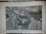
TX-Lou I have an Ej207 and my coolant lines are just like yours. I made my own hard line to connect D and E together. I used some A/C hard lines and bent them tell I got the shape I needed. Then I used and cut the U line FFR provided to connect everything up. Here are a few pictures.

I have a few other on my website here --> http://redfogo.com/index.php/catch-can-install/
I will make sure to add a section about this on my website under a coolant line tab when I get the chance!
-
Senior Member
Thanks guys, that helps a lot!
I'll try to take a better picture of J as soon as I can.
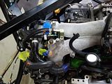
So, if A and H are the hoses that attach to the hard lines that run along the stock Intercooler and are used for oil suction, what do you recommend I do with them? I can pull off the hard lines from the stock intercooler and connect them like they used to be. However, when they connect to those hard lines there are three connections. One for A and H respectively. Then there is the last connection that has to go somewhere. I have a picture from our tear down that makes me think it goes to J. But that really confuses me since J is attached to the cold air intake. PhotoBucket is down right now so I can't post it. I will as soon as I can. J is the connection that comes off the bottom of the intake in STiPWRD's photo of the wastegate hoses. It is the one to the bottom left of the picture that appears just on top of the right side of the box underneath the intake pipe.
Thanks,
- Lou
-
Senior Member
Photobucket is back. Here is the picture with A and H labeled, and a line on the 3rd hose that I think may go into J.
Thanks,
- Lou
-
Senior Member
Head breather tubes & crossover. Are you going to run a Air/Oil separator? If so you will run new lines from H (& H) into the AOS. Otherwise, if I remember correctly they plumb into the PVC.
WRXPVC_diagram.jpg
818SC chassis #206 EJ207 2.0L VF37 twin scroll || Cusco type RS 1.5 LSD || Wilwood pedal box (firewall attach) || Wilwood superlite front calipers
BUILD Phase 1: 6/6/2014 car delivered || 5/24/2015 first start || 6/7/2015 go karted || 4/20/2016 hard-top-topped || 10/25/2016 registered || 11/18/2016 inspected & complete
BUILD Phase 2: 3/8/2017 EJ207v8 || 5/29/2017 re-first re-start || 7/17/2017 re-assembled with race car bits
-
Senior Member
Mike beat me to it but here's another site showing the same diagram:
http://opposedforces.com/parts/impre...llustration_8/
A and H come off each cylinder head and get T-d together to J. Since J is on the intake tube, it will always see vacuum and (I guess) suck oil vapors from the heads? This is the reason I'm running an oil catch can in between, so my intake doesn't get covered in oil mist.
This may also be useful for figuring out C:
http://opposedforces.com/parts/impre...llustration_3/
It appears that C runs to the purge valve and purge solenoid coming off the front of the intake manifold.
-
Senior Member
Awesome! It is all making sense now. That is definitely it. I'll go with a catch-can as well.
I think that answers all of my questions.
I've got M hooked up already with the Blouch braided line and banjo fitting with new crush washers. Plugs have been ordered. Now I just need to plumb a few connections, find the wastegate solenoid and hoses and put in a catch-can.
Thanks again!
- Lou
 Posting Permissions
- You may not post new threads
- You may not post replies
- You may not post attachments
- You may not edit your posts
-
Forum Rules

Visit our community sponsor


 Reply With Quote


