FormaCars

Visit our community sponsor

Thanks Thanks:  0
Likes Likes:  0
Page 3 of 6 FirstFirst 12345 ... LastLast
Results 81 to 120 of 204

Thread: Frame Mods to Type 65 Coupe

  1. #81
    Trick Tool Maker, Super Moderator Hankl's Avatar
    Join Date
    Feb 2011
    Location
    Northern CA
    Posts
    671
    Post Thanks / Like
    Blog Entries
    1

    Smile

    What zip code does the Elephant use, I can't send a mail to his address without one.....

    Hank
    “If you didn’t have enough time to do it right the first time. How come you always have time to go back and do it again?” FFR1000186CP

    Understeer is when you hit the wall with the front of the car and oversteer is when you hit the wall with the rear of the car.
    Horsepower is how fast you hit the wall and torque is how far you take the wall with you.

  2. #82

    Join Date
    May 2011
    Location
    Pittsburgh, PA
    Posts
    728
    Post Thanks / Like
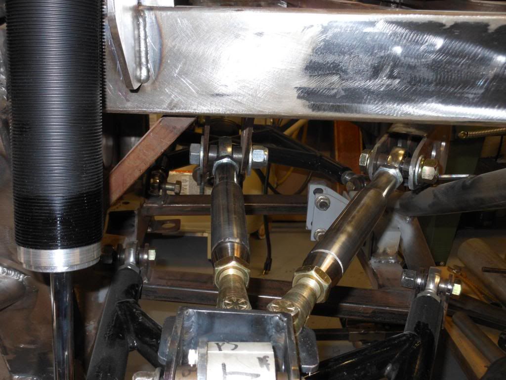
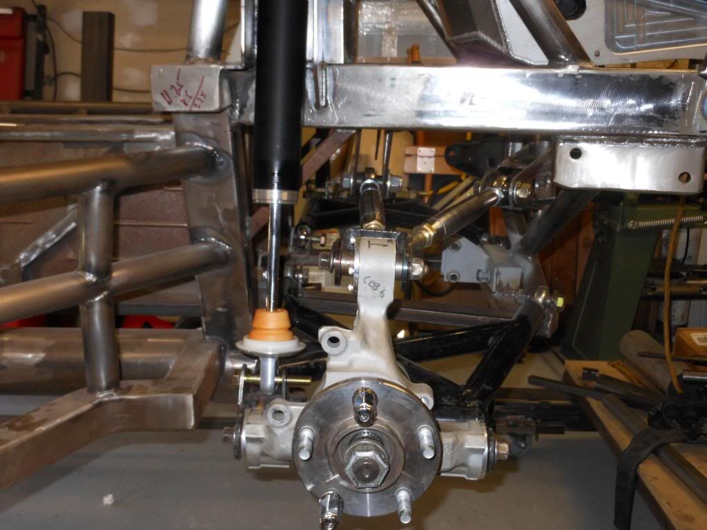
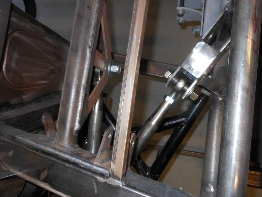
    I mentioned above that Hank and I have a few more tricks up our sleeve to tweak the IRS for extreme track duty. I will preface this by saying that my comments and mods should not be taken as an indictment or rebuke of the stock FFR IRS system, but rather, like many other builders have done in many other areas, an attempt to squeeze every last bit of performance out of what we have been fortunate enough to have been given to work with.

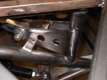
    I will defer to Hank and let him have the final word on what is going on here since the new "A" arm design is the product of his considerable talents and dedication to absolutely maximizing these cars' performance. As I understand it our goal was to counteract the twisting load on the lower control arms under heavy braking, i.e., repeated, full-on braking from high speeds with massive, sticky race tires in the road racing context. A second goal, as I see it, was to strengthen the system directly in line with where the greatest force would exist during heavy cornering.

    Here is a collection of photos:

    IRS Mod 1.JPG

    IRS Mod 2.JPG

    IRS Mod 3.JPG

    IRS Mod 4.JPG

    IRS Mod 5.JPG

    IRS Mod 6.JPG

    IRS Mod 7.JPG

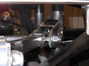
    The new arm uses 1 rod end/tube end with right hand threads, and another set with left hand threads. In doing so, the length is infinitely adjustable, rather than just giving you whatever adjustment a half turn on the rod end yields, which is what you'd have with two sets of right hand threads. Also, the bearings in the aluminum knuckle are the full, 3 piece Whitby kit. There is literally no deflection in the lower bearings, so the location of the new pivot point at the back of the frame needs to be right on or it will bind a little during movement. I will post some additional photos and comments before too long.
    Last edited by Jacob McCrea; 08-20-2012 at 08:42 AM. Reason: Typo and additional info

  3. #83

    Join Date
    Feb 2011
    Location
    Colorado Springs
    Posts
    1,382
    Post Thanks / Like
    Funny you should post this. I'v been thinking of doing the same thing. I was going to modify the upper arm to look like the a Superformance arm. But that was going to make changing rear camber a real pain in the neck, so I have been reluctant to make the change. But I really like your method. Changing the camber would be a breeze.

    I will blatently copy your design, and then take full credit for being a brilliant engineer

    I would also like to change the poly bushings to spherical bearings. I hear the ERA kit is pretty good.
    .boB "Iron Man"
    NASA Rocky Mountain, TTU #42, HPDE Instructor
    BDR 1642: Coyote, 6 Speed Auto, Edelbrock Supercharger
    Member: www.MileHiCobraClub.com
    www.RacingTheExocet.com

  4. #84
    Member
    Join Date
    Feb 2011
    Posts
    30
    Post Thanks / Like
    As Bob Cowan, I too have thought about strengthening the upper mount for the IRS. For street duty, the original design is probably fine, but for track duty, seems like a bit more robust system would be advisable. Along with the shock mount position change, this mod should do the trick. I will be probably be incorporating them on my build as well. Spherical bearings would also be a must for exuberant driving duty.
    Jim

    CP 438, FR 347, TKO 600, Levy/Wilwood 6P/4P

  5. #85
    Trick Tool Maker, Super Moderator Hankl's Avatar
    Join Date
    Feb 2011
    Location
    Northern CA
    Posts
    671
    Post Thanks / Like
    Blog Entries
    1
    To expand a little on what is going on here, Jake and severals other coupe builders have been on a path to ensuring that the broken "H" arm is no longer a problem for the Competition Coupes that use the IRS systems.
    Let me say for everyone, that this problem is limited to only the Track Cars, the street driven Coupes do not have these problems. The track Coupes are generating so much torque in the system, that we needed to
    do some modifications to cure the problem.

    Let me give you a little background, when Ford initially designed the IRS system for the T-Bird, they used rubber bushings in the knuckle pivot points, a rigid lower H-arm,
    and a U-Channel upper arm, basically the system worked very well in the large framed car. What happened when several manufactures, not just FFR, started to use the IRS, some changes were made to adapt it to the
    particular manufactures cars. It appears that everyone followed the same, or nearly the same path on adapting the IRS. Specifically, using a single point at the upper inner pivot point with a Heim Joint/Rod End, and a
    simple U attachment at the knuckle, no problem so far.

    The problem started, when we began doubling and tripling the springs loads on the Competition Coupe suspension, and, this is the most Important part of the equation, started generating substantially larger brake torque loads.
    We have seen race speeds in excess of 150 MPH, for sustained periods, which equated to increases in brake loads/torque, to reduce speed for corner navigation. When Karen broke the first of two H-arms, we first suspected metal fatigue,
    as that was the most logical to assume. Not until she broke the second arm, did we suspect that something else was causing the problem. We all sat down trying to figure what was happening, not till we saw an original picture of the T-bird
    suspension, did we see what had happened.

    In the process of insuring that the inner camber pivot point did not bind, almost every manufacture resorted to a spherical bearing for the new pivot. What this did for normally driven cars was predicable, smooth ride with no binding as a result,
    for the Race Coupes it was something different, and here is where the evolution of the need for changes really takes off.

    There were three phases of changes that lead to the current conditions as I see it, although some may disagree. The first change made was the addition of spherical bearings to the IRS knuckles by Nate and Alison Hine, which resulted in predicable
    movement of the IRS knuckle. This mod allowed the knuckles to move freely and not bind during radical movement, something the rubber bushings prevented.

    Phase two, the movement of the shock from the rear inner position, to a forward and outward position. This resulted in lower needed spring rates due to a change in the motion ratio of the shock/suspension relationship. I had at the time asked
    several suspension experts about the question I had about the brake torque situation, as I surmised that moving the shock to the front would encourage a twisting motion of the “H” arm. I was assured that it would be OK. I need to state here,
    that no one at FFR had been asked for their input, so our modifications were what we thought they should be, not an action endorsed by FFR at any point.

    Phase three, Karen driving the Coupe WAY TOO FAST! and bigger brakes. A change had been made to larger brakes, and guess what, that was the coup de grâce! We made the brake torque exceed what the lower “H” arm could handle with the previous modifications.

    So several of us put our heads together and we find ourselves at this point. To put it in simple terms, we needed to arrest the torque the knuckle had to deal with. A simple solution is the best, so as of now we are going with a upper A-arm
    configuration. Jake and I, along with input from several racers are piloting a A-arm fix. Both Coupes with the fix should be on track early next year, if we don’t decide to change the rest of the car in the process...

    FFR did not build the Coupes (or the roadsters for that matter) to be full-on race cars, so it's on us to make the needed improvements....Really, this is the way race car development had happened for years....Manufacturers design and
    produce cool, wicked fast cars, and racers take them to the next level, making evey modifications needed along the way....The Corvette, the Mustang, and the Datsun B-210's and Z-cars all come to mind....Great modifiers and fabricators
    went so far as to take a full working chassis and re-work the **** out of it to take it to a whole new level....Hmmm...Mickey Thompson, Phil Remington and Peter Brock come to mind....What we're doing is just normal in terms of race car
    development.....You can only go as fast as your weakest link.... that WAS the IRS system.....The loose nut behind the wheel, is another matter open for discussion!

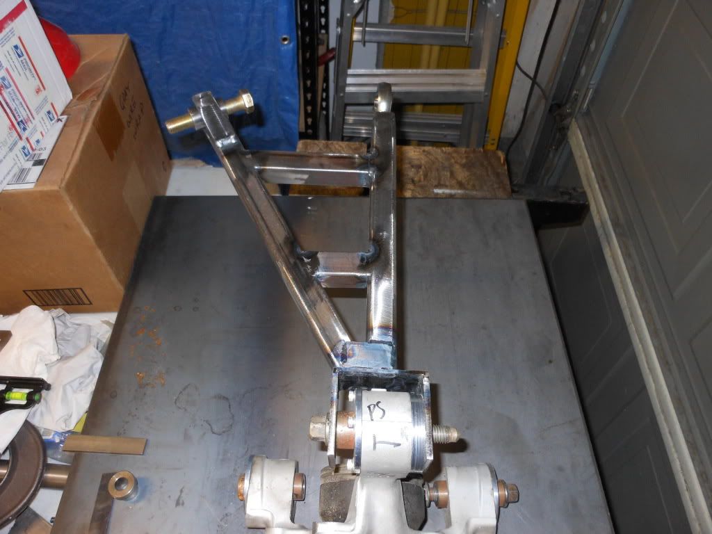
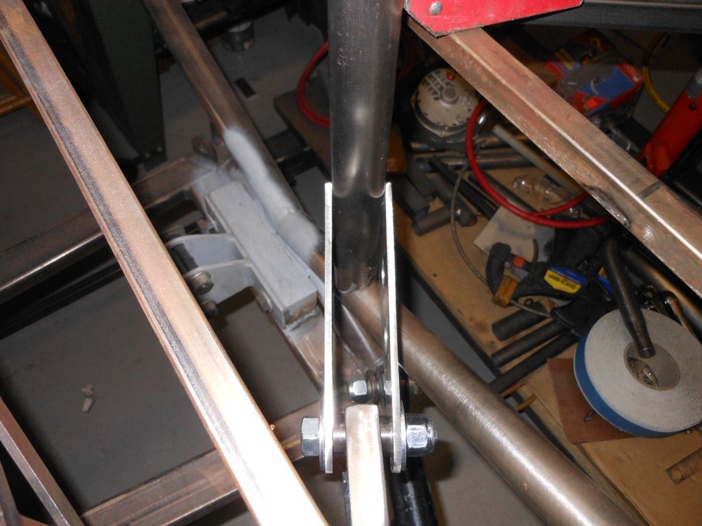
    Jig for Rear Mount, this will locate the rear mounting point for the new top A-Arm. It maintains the angular relationship identical to the lower arm.


    Hank
    Last edited by Hankl; 08-24-2012 at 03:09 AM.
    “If you didn’t have enough time to do it right the first time. How come you always have time to go back and do it again?” FFR1000186CP

    Understeer is when you hit the wall with the front of the car and oversteer is when you hit the wall with the rear of the car.
    Horsepower is how fast you hit the wall and torque is how far you take the wall with you.

  6. #86
    Trick Tool Maker, Super Moderator Hankl's Avatar
    Join Date
    Feb 2011
    Location
    Northern CA
    Posts
    671
    Post Thanks / Like
    Blog Entries
    1
    Hey Gang,

    Last post was about the new Jig that Jake had lead me to design, here's the follow-up.

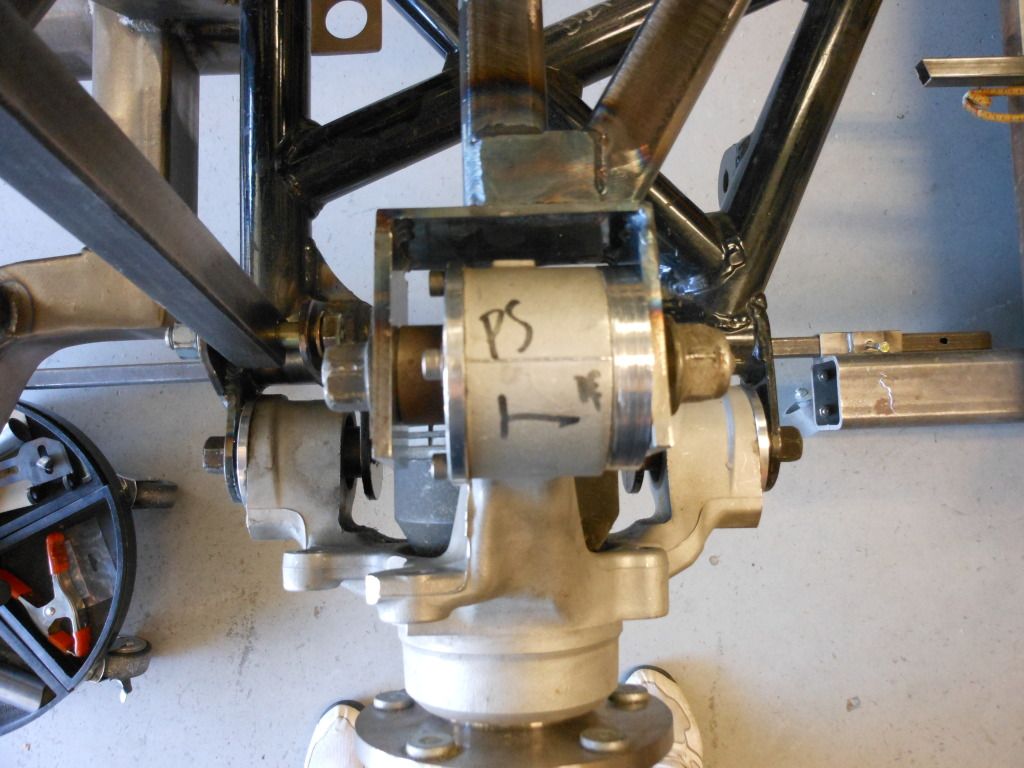
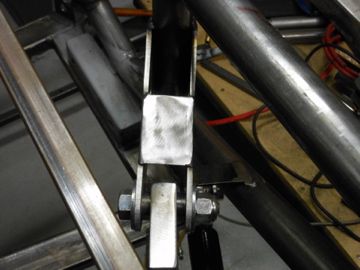
    The pictures below show the jig mounted on the knuckle, and the end relationship with the chassis.
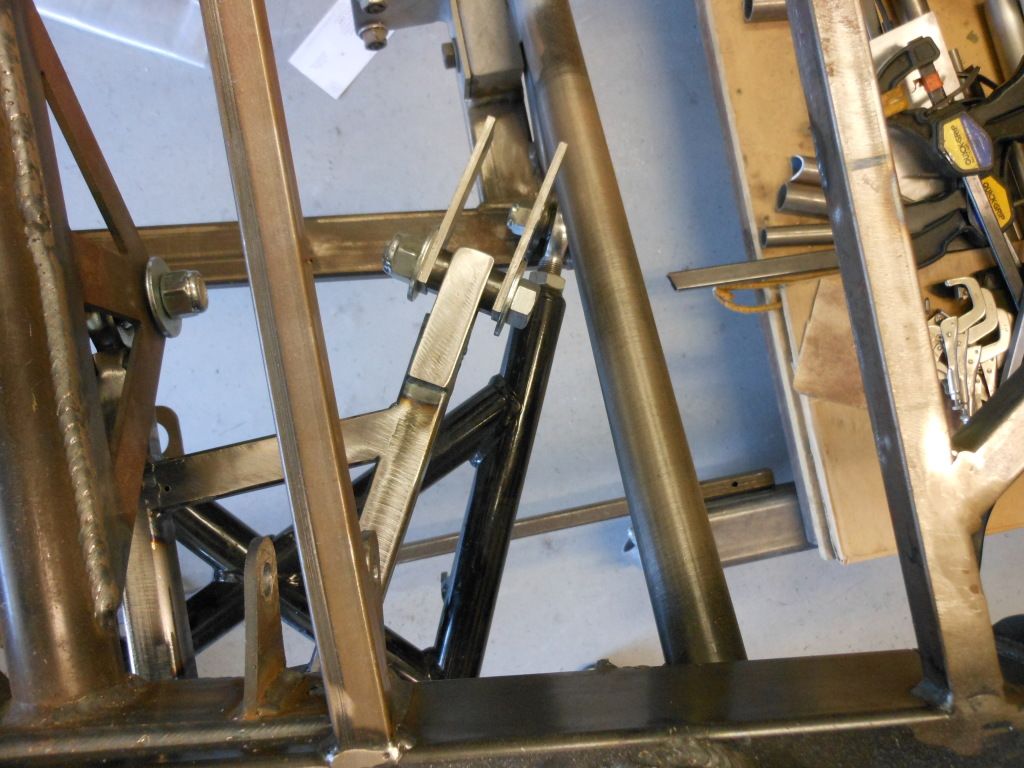
    Jake gave me the idea of going with a mount that used the existing rear IRS support, and adding
    a new cross bar, and short verticals supports, to link the A-arm mount to.

    I made a spacer out of 6061 T6 to insert between the jig and the Knuckle. Once installed, the jig
    doesn't move at all, big time rigid!! The angle set by the lower H-arm is mimicked by the angle at
    the top of the knuckle, and then to the rear mounting point for the upper A-arm.


    Top view of the Jig and the points that I'll need to make to weld the new brackets to. This also shows
    the complexity in insuring that the geometry of the lower H-arm is mimicked by the upper A-arm


    Jake has been a GREAT PARTNER in this, without us bouncing stuff off of each other, I don't think I would have
    seen what was right in front of me. It's good for Anal Retentive types to get together!!

    Hank
    “If you didn’t have enough time to do it right the first time. How come you always have time to go back and do it again?” FFR1000186CP

    Understeer is when you hit the wall with the front of the car and oversteer is when you hit the wall with the rear of the car.
    Horsepower is how fast you hit the wall and torque is how far you take the wall with you.

  7. #87
    Trick Tool Maker, Super Moderator Hankl's Avatar
    Join Date
    Feb 2011
    Location
    Northern CA
    Posts
    671
    Post Thanks / Like
    Blog Entries
    1
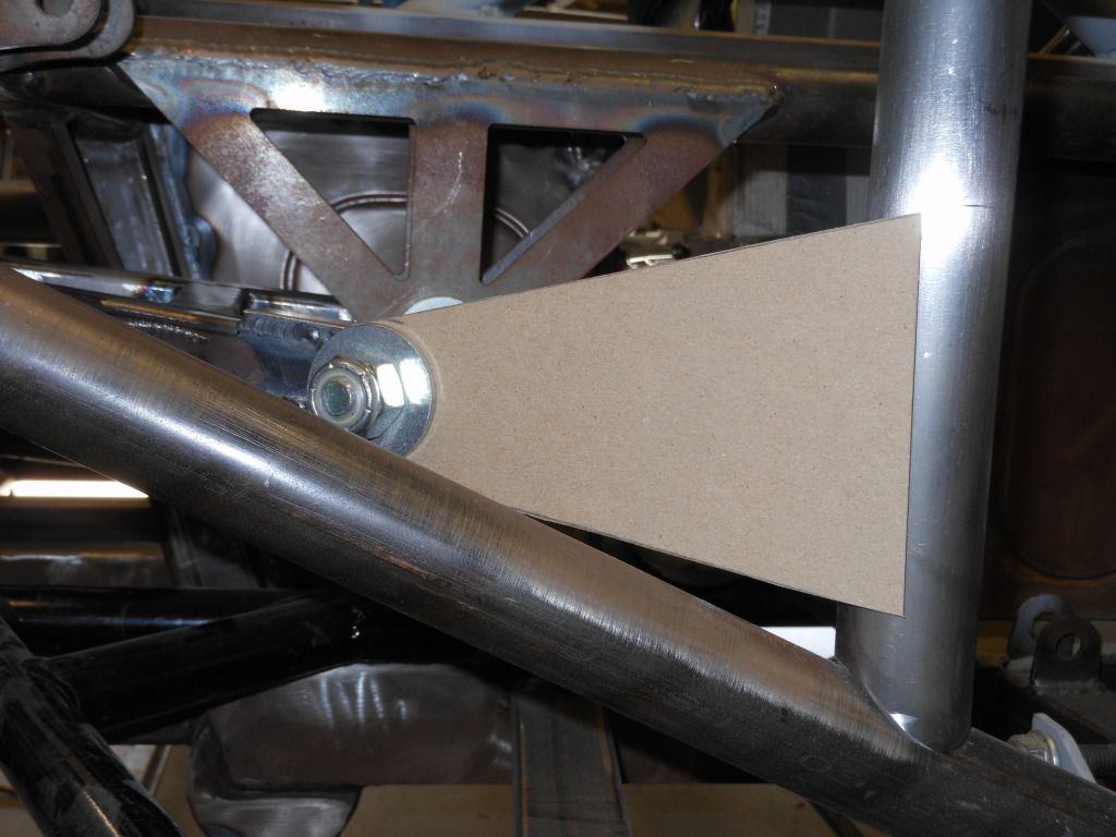
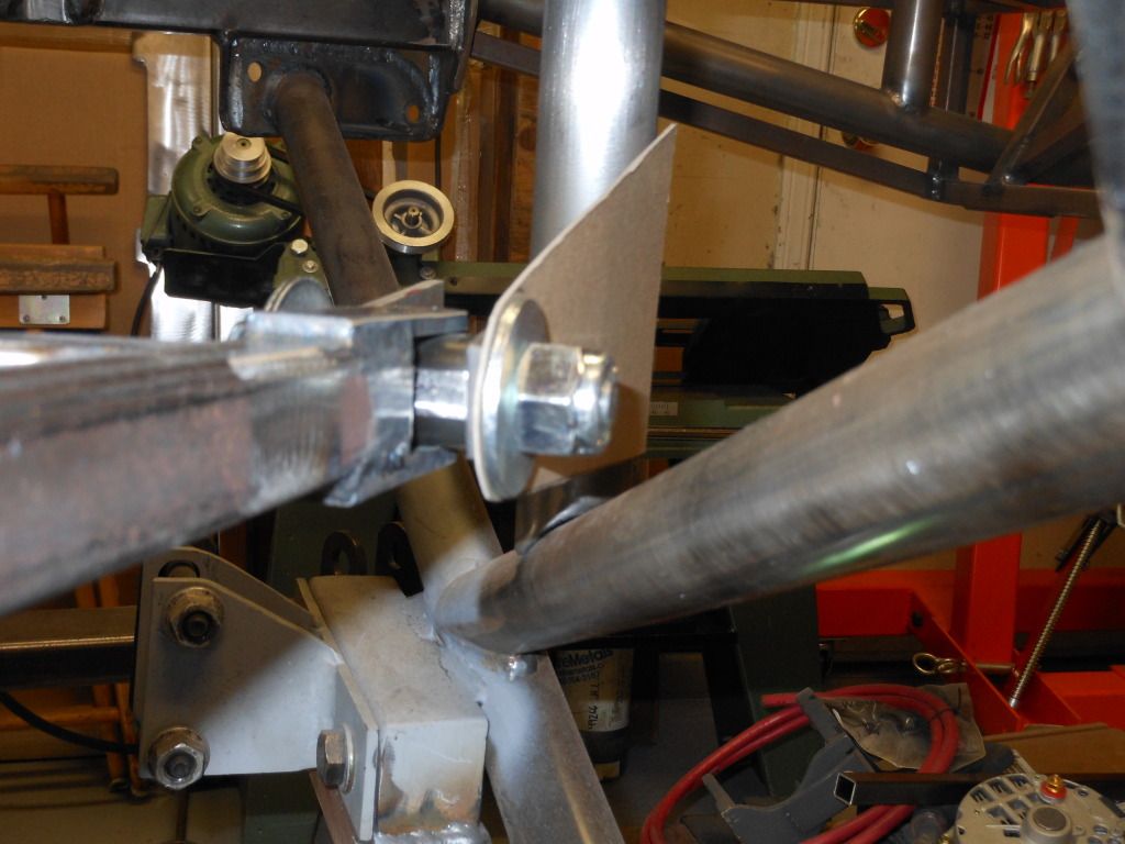
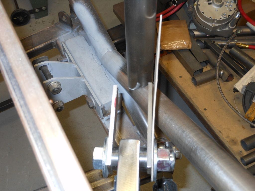
    A little more today on making brackets for the A-arm rear mount, just made from "Chip Board"


    View from the top of the knuckle.


    A better view from the top, it shows the vertical mount that the A-arm brackets attaches to, this was the mod that Jake came up with.
    Plenty of room to get wrenches in there, not crowded at all, even though it looks tight..


    Hank
    Last edited by Hankl; 09-18-2012 at 12:41 PM.
    “If you didn’t have enough time to do it right the first time. How come you always have time to go back and do it again?” FFR1000186CP

    Understeer is when you hit the wall with the front of the car and oversteer is when you hit the wall with the rear of the car.
    Horsepower is how fast you hit the wall and torque is how far you take the wall with you.

  8. #88

    Join Date
    May 2011
    Location
    Pittsburgh, PA
    Posts
    728
    Post Thanks / Like
    Looks good, Hank; very nice! Glad to be working with you on this. I appreciate the detailed history recited above.

    I initially added the round tube tying the frame rails together directly above the IRS "X" tubing as I speculated that Karen's axle problems were caused by frame flex, i.e., the framerails flexing in corners and popping the axles out of place. I believe my speculation was wrong, but the tubing ended up becoming part of the structure for the new IRS pivot.

    Hank and I considered a lot of options in making the new upper IRS arm to fully arrest braking torque. We looked into, to varying degrees, using the upper A arm from a '03-'04 Cobra, "reversing" the current design with a pivot in front of the factory upper arm, making a "drag link" or Panhard-type bar from the upper control arm and running back to the quad shock mounts, and even making a miniature, "sideways" Watt's link on the upper control arm. Karen and Rick had to endure being CC'd on a month's worth of emails with "back of the envelope" calculations literally drawn on the back of envelopes, shaky hand-drawn diagrams, etc.

    As for my build, it will be a big challenge to keep it light given all of the metal I've added. But here are some photos of a few things I just did to trim some of the weight. There is more to come.

    This photo and the one below it show the transmission tunnel top tubes re-fabricated in aluminum. They will be screwed in with machine screws and removable for easy transmission access. I used a Miller Spoolmate 100 spool gun hooked up to my mig machine. It took some practice to adjust to the new (to me) process and the weld appearance is nothing to boast about, but everything stuck together fine.

    Aluminum Cross Bars.JPG

    Aluminum Cross Bars 2.JPG

    You can see here that I removed the lower 3/4" square tube, which was redundant given the .120 DOM tube I added for fuel cell protection.

    Redundant Tube Removed.JPG

    The same thing happened here - I removed the lower horizontal 3/4" square tube, which as far as I could tell served no purpose given the way I added the rear fuel cell protection tube (there is a better and simpler way to do the fuel cell protection tubes shown in Karen's build thread).

    Redundant Tube Removed 2.JPG

    I will post some photos and explanation of how I located the new IRS pivot. It was somewhat convoluted. Thanks for checking this out.

  9. #89
    Senior Member
    Join Date
    Feb 2011
    Location
    Gorham, ME
    Posts
    253
    Post Thanks / Like
    Jacob

    Seems the lower outer ends of the "H" arm attachments to the upright look flimsy as compared to the robust arm itself and the robust weldment at the upper arm attachement to the upright.

    Bill

  10. #90
    Trick Tool Maker, Super Moderator Hankl's Avatar
    Join Date
    Feb 2011
    Location
    Northern CA
    Posts
    671
    Post Thanks / Like
    Blog Entries
    1
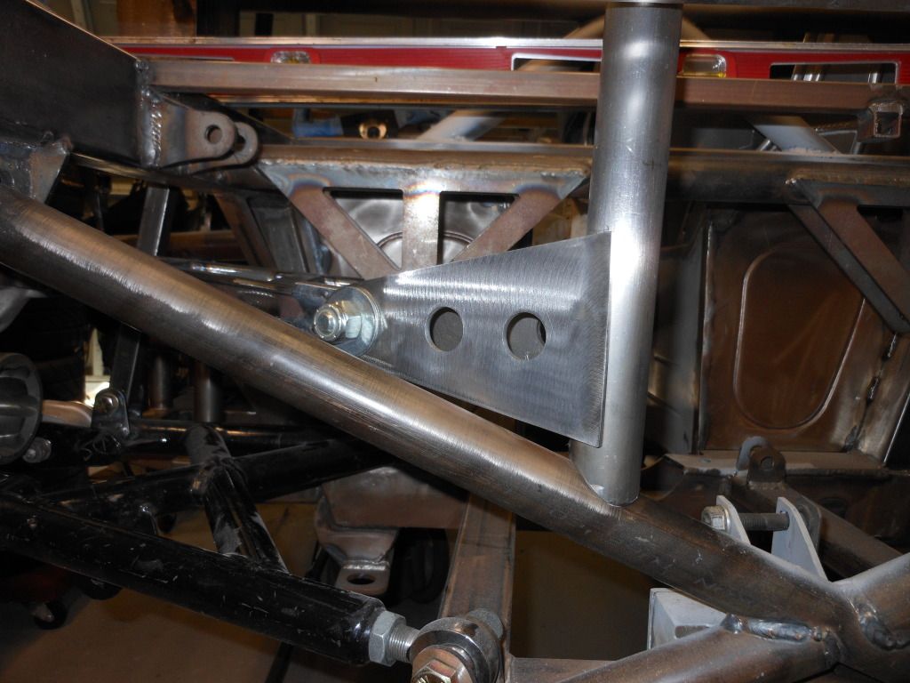
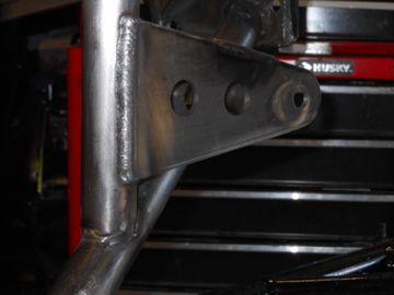
    Here are the brackets I finished today, mocked-up so you can see the final layout. Some lightening holes, 3/16" Mild Steel, same as the rest of the
    suspension mounts. Waiting for some 1 1/2" .120 Wall D.O.M. tubing to finish up


    Hank
    “If you didn’t have enough time to do it right the first time. How come you always have time to go back and do it again?” FFR1000186CP

    Understeer is when you hit the wall with the front of the car and oversteer is when you hit the wall with the rear of the car.
    Horsepower is how fast you hit the wall and torque is how far you take the wall with you.

  11. #91
    Senior Member CHOTIS BILL's Avatar
    Join Date
    May 2011
    Posts
    427
    Post Thanks / Like
    Blog Entries
    1
    Hankl,

    Has anyone given any thought of raising the rear roll center height? I did a quick check on my car and it didn’t seem to be a correct so I talked to FFR about the rear RC height and even though out number didn’t match both seem to be on the low side compared to the front roll center. I had a similar situation with my DSR which had about the same weight distribution but with a lower center of gravity so are not directly comparable but when I raised the rear RC it really helped from mid corner to full throttle. I was wondering if during all your hard work you addressed the roll center height at all.

    Thanks

    Bill Lomenick
    Chotis Bill

  12. #92
    Trick Tool Maker, Super Moderator Hankl's Avatar
    Join Date
    Feb 2011
    Location
    Northern CA
    Posts
    671
    Post Thanks / Like
    Blog Entries
    1
    Bill,

    According to all of the information we have, the Roll Center on the IRS is optimum for what we have to deal with, i.e., OEM parts used/location restraints, we would have to move all of the suspension mounting
    points to affect any changes. From what I recall from conversations with David Borden, the IRS complements the handling of the car vs hindering it, and if I'm correct, David mentioned that the IRS was better
    than the Live Axle in reference to the Roll Center.

    Hank
    “If you didn’t have enough time to do it right the first time. How come you always have time to go back and do it again?” FFR1000186CP

    Understeer is when you hit the wall with the front of the car and oversteer is when you hit the wall with the rear of the car.
    Horsepower is how fast you hit the wall and torque is how far you take the wall with you.

  13. #93
    Senior Member CHOTIS BILL's Avatar
    Join Date
    May 2011
    Posts
    427
    Post Thanks / Like
    Blog Entries
    1
    Thanks Hank,

    With out making a change and trying it out it would be hard to know what effect it would have and that does take a lot of time and effort. I haven’t looked into this very much but just changing the upper control arm inboard mounting point should be all that is needed to change the roll cent height but may cause interference other places. Just a thought.

    Thanks,

    Bill Lomenick
    Chotis Bill

  14. #94
    Trick Tool Maker, Super Moderator Hankl's Avatar
    Join Date
    Feb 2011
    Location
    Northern CA
    Posts
    671
    Post Thanks / Like
    Blog Entries
    1
    Bill,

    I understand the thought process, always endeavoring to make this better. Just thinking off the top of my head, on a Live axle, we usually bend the axle tubes for a 1/2-3/4 degree of negative camber, as that is usually what the bearing will take. With the IRS we can start out with as much or as little Camber as we want, so we have a substantial advantage right there. I think Roll Center adjustment has always been critical for the front suspension to operate as needed, but the rear, for me at least, is more of a secondary factor. I just put a call into Karen to get some feed back from the new 3 Link Coupe, vs, the IRS Coupe. I'll let you know what I learn from that conversation.

    Hank

    Just did a little more thinking about your post, actually moving the upper mount would be one of the easier things we've been up to. Running the current mounting points against new locations with a Suspension Sim would be a good thing, know of anyone that would have the software/could run a couple of scenarios for us?
    Last edited by Hankl; 09-21-2012 at 01:29 PM.
    “If you didn’t have enough time to do it right the first time. How come you always have time to go back and do it again?” FFR1000186CP

    Understeer is when you hit the wall with the front of the car and oversteer is when you hit the wall with the rear of the car.
    Horsepower is how fast you hit the wall and torque is how far you take the wall with you.

  15. #95
    Senior Member
    Join Date
    May 2012
    Posts
    304
    Post Thanks / Like
    Stop me where I get this wrong - the caliper rotates the carrier in when compressing the rotor, causing the upper connection to move forward toward the front of the car, twisting the lower A-arm.

    I reading way to many car mags in the '70s and 80's, especially articles on F1, Can Am, Trans Am, etc. suspension design. I see adding a trailing link to the top A-arm to arrest the rotation of the spindle. It will be in compression (not good,) but it would stop the rotation.

    There's a lot more to it than that, the travel has to be complementary and not negatively affect caster or camber, introduce bump steer, etc. I was a bit surprised not to see one the first time I viewed the chassis layout, as it seemed a natural to me.

  16. #96
    Trick Tool Maker, Super Moderator Hankl's Avatar
    Join Date
    Feb 2011
    Location
    Northern CA
    Posts
    671
    Post Thanks / Like
    Blog Entries
    1
    Tirod,

    What we are doing here is adding a rear portion of what would be referred to loosely as an A-arm on the upper knuckle pivot point. The mount has been place in such a location as to mimic the angular movement of the lower "H" arm in the IRS. The lower "H" arm performs the combined function of the IFS lower A-arm, and a Tie Rod, in that it controls the upward and side to side motion at the lower part of the knuckle. Since the lower portion of the knuckle is fixed by the H arm, the H arm in effect eliminates any Bump Steer & Caster, as that is a front end suspension problem that is not germane to the IRS. As to the camber, that is controlled by the upper mount, shorting increases negative camber, and lengthening provides the opposite result. The rear link is in tension, and it is not a "Trailing Link", so that is also not applicable to the design.

    REAR OF CHASSIS........................................... .................................................. .................................................. .................... FRONT OF CHASSIS

    This is the Jig, not the actual tubing used.


    Hank
    Last edited by Hankl; 09-22-2012 at 11:50 AM.
    “If you didn’t have enough time to do it right the first time. How come you always have time to go back and do it again?” FFR1000186CP

    Understeer is when you hit the wall with the front of the car and oversteer is when you hit the wall with the rear of the car.
    Horsepower is how fast you hit the wall and torque is how far you take the wall with you.

  17. #97
    Senior Member CHOTIS BILL's Avatar
    Join Date
    May 2011
    Posts
    427
    Post Thanks / Like
    Blog Entries
    1
    Hank,

    I use WinGeo by Bill Mitchell but I am not sure of the pickup point locations that I measured on my car since I took the measurements with the car up on blocks and not on my scales. I was going to get the car on the scales and check the numbers I came up with but if someone could get me the pickup point locations we have now and what change you would like to try I can run them and see what needs to change.

    Bill Lomenick
    Chotis Bill

  18. #98
    Super Moderator vnmsss's Avatar
    Join Date
    Feb 2011
    Location
    California
    Posts
    649
    Post Thanks / Like
    Blog Entries
    13
    Hank...It was good talking with you last evening. I appreciate the detailed background you have provided in this thread, as well as the explanation of the ongoing thought process in the development of what will be a more stabilized IRS.

    In regards to the comparison of the 3-link in my new Coupe with the modified IRS in my older Coupe, the new car (3-link) certainly felt stable and responsive in the two trackdays in which I have participated. As we discussed, a number of changes that were made in the new build were the result of our on-track experiences with the first car. Other than moving to a 3-link system, we chose to use of the FFR spindles in the build, and I believe it was a good decision, as the front suspension geometry produces a ton of grip and good turn in, while also creating zero bumpsteer (with the use of rack extenders).

    Early in 2010, and with your design and direct assistance, we changed the rear shock location (outboard) on our older Coupe, and that singular change made a world of difference in the car's overall stability and handling. The addition of the SAI mod (Dave Borden's design) added another level of sophistication and performance enhancement to the car's handling....As the old saying goes though, a system is only as strong as the weakest link, and as we "fixed" one issue, we inevitably found the next "weakest link.".....The ever loosening wheel bearings and constant movement/excessive wearing of the hubs are symptomatic of the next area in need of attention, which is arresting movement in the UCA area.....In the middle of all of this, we also stumbled upon the issue with the axles being machined too short, which certainly added another dimension to the challenge.....

    If I were to venture a guess, I think that 99 out of every 100 FFR builders using an IRS in their cars will never experience the issues we've had, if for no other reason other than the fact that they will never be pushing their cars to the extreme conditions such as we experienced in the 25 hours.....That said, we know there are issues a number of builders have already faced with the IRS, and working together, it's our hope that we can provide improvements for our own use, as well as for the benefit of others.

    It's been a pleasure to work with Hank on the challenges we've faced, and I have truly appreciated Jake McCrae's insights and execution of various steps in the development process as well. Bill (Chotis Bill), thanks for offering to help us...While some may question the thought process (welcomed critsicm BTW, which helps assure we're not Kool-Aide drinking over here), your offer of pragmatic, on-the-ground assistance in running the numbers is much appreciated.

    Thanks again everyone!!!!

    Karen
    Last edited by vnmsss; 09-22-2012 at 07:30 PM.
    #28 FFR Challenge Series
    #28 FFR Type-65 Coupe
    2011 Western Endurance Racing Championship
    2010 West Coast Champion
    Drive it.....Like you stole it!

  19. #99
    Senior Member CHOTIS BILL's Avatar
    Join Date
    May 2011
    Posts
    427
    Post Thanks / Like
    Blog Entries
    1
    Karen,

    I hope no one interpreted what I wrote as a criticism in any way. I have designed the suspension systems on many of the race cars that I have built and know there is no one correct design. I was just curious with all the work that was being done if changing things like the roll center was considered since it can help correct a problem if one even exists. The only reason I mentioned roll center is because of all the work being done to the upper control arm and that is the easiest place to play roll centers. Anti-squat is also a powerful tool to tune suspension but that requires changing the lower control arms pickup points to do the most good and that is another big job.

    Bill Lomenick
    Chotis Bill

  20. #100
    Super Moderator vnmsss's Avatar
    Join Date
    Feb 2011
    Location
    California
    Posts
    649
    Post Thanks / Like
    Blog Entries
    13
    Hi Bill......No worries...No one here took your input as anything other than great questions and great brainpower, which is helping us work through these issues....I have a great respect for your experience, and we truly appreciate your offer to help!! ;.)) Thanks!!

    Karen
    #28 FFR Challenge Series
    #28 FFR Type-65 Coupe
    2011 Western Endurance Racing Championship
    2010 West Coast Champion
    Drive it.....Like you stole it!

  21. #101

    Join Date
    May 2011
    Location
    Pittsburgh, PA
    Posts
    728
    Post Thanks / Like
    My frame mods have almost come to an end, and yesterday I picked up the frame from the powder coater. They did a very thorough job on it, blasting it with a fine medium (titanium dioxide if I recall), followed by pre-treatment with iron phosphate (again, if I recall), followed by a powder primer and a powder top coat. It was quite a bit more expensive than what FFR charges, if anyone is wondering, but since the car will hopefully change hands via my will, I wanted it to be as durable as possible.

    I owe a hearty thanks to everyone who has commented above and offered help and guidance to me in the process; it was and is recognized and very much appreciated. Here are a few photos:

    Finished Frame 1.JPG
    Finished Frame 2.JPG
    Finished Frame 3.JPG
    Finished Frame 4.JPG

    I still have a few ideas to lighten up the frame on this thing, which I hope to post here before too long.

  22. #102
    Senior Member johngeorge's Avatar
    Join Date
    Feb 2011
    Location
    Nashua, NH
    Posts
    878
    Post Thanks / Like
    Jacob, looks great! nice job
    ***SOLD!!! - NASA ST2 FFR#48 Gen3 Type65 Coupe R, Street legal.***
    ***SOLD!!! - NASA ST2 FFR#48 Challenge Car rolling chassis, Street legal.***
    http://johngeorgeracing.com

  23. #103
    Super Moderator vnmsss's Avatar
    Join Date
    Feb 2011
    Location
    California
    Posts
    649
    Post Thanks / Like
    Blog Entries
    13
    Awesome job Jacob!!!!!! Hank's Coupe is coming along nicely, and I know there are a number of others out there building as well...Can't wait for us to get our Competiton Coupes on track together!

    Karen
    #28 FFR Challenge Series
    #28 FFR Type-65 Coupe
    2011 Western Endurance Racing Championship
    2010 West Coast Champion
    Drive it.....Like you stole it!

  24. #104
    Trick Tool Maker, Super Moderator Hankl's Avatar
    Join Date
    Feb 2011
    Location
    Northern CA
    Posts
    671
    Post Thanks / Like
    Blog Entries
    1
    Hey Gang,

    Been really busy the last couple of weeks with school, Russ Foster called to see if I had fallen of the end of the earth, no, but going to classes all day long feels like it.
    Here's what I did last weekend, getting closer to the powder coat phase.


    Hank
    “If you didn’t have enough time to do it right the first time. How come you always have time to go back and do it again?” FFR1000186CP

    Understeer is when you hit the wall with the front of the car and oversteer is when you hit the wall with the rear of the car.
    Horsepower is how fast you hit the wall and torque is how far you take the wall with you.

  25. #105

    Join Date
    May 2011
    Location
    Pittsburgh, PA
    Posts
    728
    Post Thanks / Like
    That looks really good, Hank.


    Quote Originally Posted by tirod View Post
    I see adding a trailing link to the top A-arm to arrest the rotation of the spindle. It will be in compression (not good,) but it would stop the rotation.
    We gave some thought to this approach, specifically running about a 12" link from the upper A arm back to the quad shock mounting area, since it initially seemed like a very easy way to solve the problem. The problem, though, is that the suspension travels up and down in a straight line, while the link moves up and down in an arc, as shown by this rough drawing:
    Back of Envelope Calculation.JPG

    With a 12" link, and assuming 4" of suspension travel, the arc of the new link "departs" from the suspension's path of travel by about 3/16" in the middle of the travel. I am pretty confident that the resulting binding would promptly show us what the weakest component in the system is. This is unfortunate because adding a link would be really easy.

    Anyway, with all the great new coupe threads going I thought I'd join in and post a few pics, despite my modest progress.

    Aluminum Panels.JPG

    Aluminum Panels 2.JPG

    Here are the completed and powder-coated upper control arms.

    IRS Upper Arms.JPG

    The super-lightweight diff breather is actually a spare fuel filter for my Stihl saws.

    IRS Vent.JPG

    I am keeping the fluid reservoirs inside the footbox for simplicity, and will make dual access panels atop the footbox.

    Triple Master Cylinder.JPG

    Modest front suspension progress; don't attach the steering arms upside-down, or on the wrong side (what I did) the first time around!

    Front Suspension.JPG

  26. #106
    Super Moderator vnmsss's Avatar
    Join Date
    Feb 2011
    Location
    California
    Posts
    649
    Post Thanks / Like
    Blog Entries
    13

    Hi Jake! Thanks so much for posting the great pictures, and congrats on the progress! You've been an an amazing supporter and fellow builder in our Competition Coupe project, and I'm stoked to see your build moving forward.

    We have some great builds going on amongst our forum members right now, and it's great that so many people are posting pictures and information for others to use in their builds (or to inspire them to make other modifications). After seeing the finished product, and in being able to follow a number of Coupe builder's progress, such as yours, an increasing number of folks are choosing to add the frame and door modifications to their cars, which is very cool.

    Tom Coon has been relentlessly working on his Coupe (don't tell anyone, but I think he's just a tad bit OCD), and I've never seen anyone make the progress he makes in such a short amount of time! His car looks amazing, and I am looking forward to stopping by his place to "oooh, and ahhh" over it next weekend.

    Thanks again for all of your assistance with the Competition Coupe build manual. The document is destined to become another milestone accomplishment and benchmark resource for our community. You rock!!

    Karen
    Last edited by vnmsss; 03-12-2013 at 12:05 AM.
    #28 FFR Challenge Series
    #28 FFR Type-65 Coupe
    2011 Western Endurance Racing Championship
    2010 West Coast Champion
    Drive it.....Like you stole it!

  27. #107
    Senior Member tcoon's Avatar
    Join Date
    Mar 2011
    Location
    Angwin, CA
    Posts
    302
    Post Thanks / Like
    Hey Jacob the car looks great! It's really cool to see forum members from all over the country picking up the competition coupe torch! Can't wait to see you on track...one small thought, I think you will find your master cylinder location to be impossible to use. At it's current location it is under the cowl of the body with the body on the car. The cowl comes about midway down the footbox. The 2x2 tube is way under the body. Even with a forward access door(which I also put on mine) you will not be able to reach the master cylinders in that location. Now is the time to change it. Keep up the good work!
    Coyote powered Daytona Coupe Competition Racecar #21
    Challenge series #21
    FFR 33 Hot Rod
    2009 3rd place NorCal series
    2010 3rd place West Coast series
    2011 2nd place NorCal, 2nd place West Coast Series, 3rd place WERC class E1

  28. #108
    Senior Member tcoon's Avatar
    Join Date
    Mar 2011
    Location
    Angwin, CA
    Posts
    302
    Post Thanks / Like
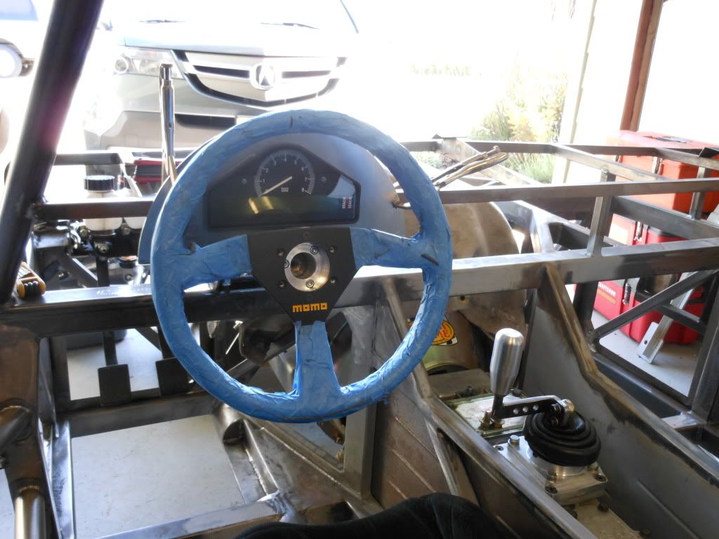
    One other thought while I'm at it...I found the steering wheel to quite high and far to the right. I lowered the shaft and moved it to the right, about 1" each direction, by notching and boxing in the 2x2 crossmember. Rick Anderson made a similar mod to Karen's car. Before I did this I could not even see the tach and speedo with the steering wheel on. I unfortunately only discovered this after the dash, wiring ,etc was completed. I then had to take all that apart to notch and weld the crossmember. Again...NOW is the time to address that issue.
    Coyote powered Daytona Coupe Competition Racecar #21
    Challenge series #21
    FFR 33 Hot Rod
    2009 3rd place NorCal series
    2010 3rd place West Coast series
    2011 2nd place NorCal, 2nd place West Coast Series, 3rd place WERC class E1

  29. #109
    Supreme Cobra Commander TimC's Avatar
    Join Date
    Feb 2011
    Location
    Flowery Branch, Ga.
    Posts
    317
    Post Thanks / Like
    Any photos of this? I'd like to drop my steering wheel just a little too. Now it would still be kind of easy but before long that are will be finished.

    Quote Originally Posted by tcoon View Post
    One other thought while I'm at it...I found the steering wheel to quite high and far to the right. I lowered the shaft and moved it to the right, about 1" each direction, by notching and boxing in the 2x2 crossmember. Rick Anderson made a similar mod to Karen's car. Before I did this I could not even see the tach and speedo with the steering wheel on. I unfortunately only discovered this after the dash, wiring ,etc was completed. I then had to take all that apart to notch and weld the crossmember. Again...NOW is the time to address that issue.
    Tim.

    Knowledge is good-Faber.

    I'm so broke I can hardly pay attention-Me.

  30. #110
    Trick Tool Maker, Super Moderator Hankl's Avatar
    Join Date
    Feb 2011
    Location
    Northern CA
    Posts
    671
    Post Thanks / Like
    Blog Entries
    1
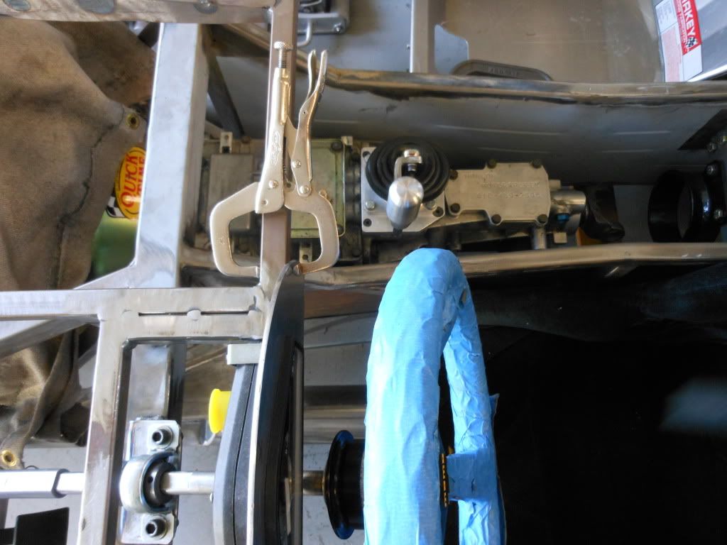
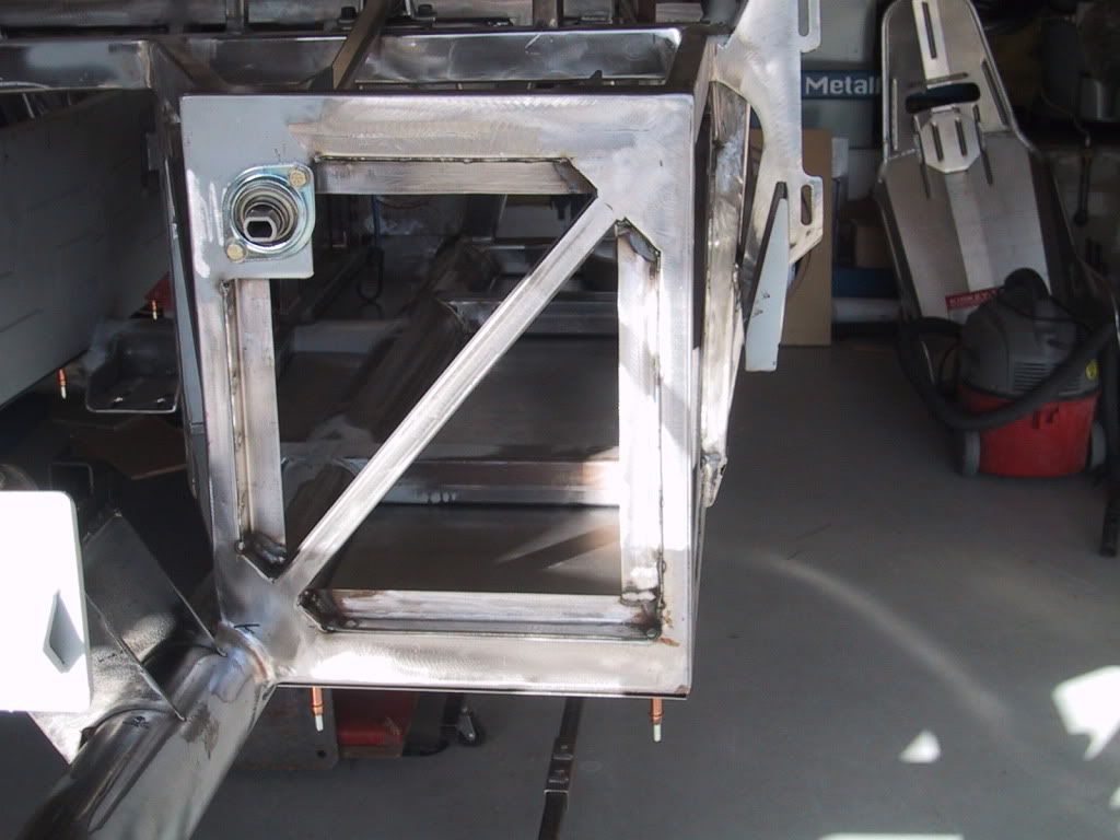
    There is actually another way to move the steering wheel. Move the location of the thru shaft bearing in the foot well.
    Moving the bearing up, lowers the steering wheel, and moving it outwards, moves the steering wheel in towards the centerline of the chassis.


    As originally configured, there is a slight cant of the wheel in the "X" axis, it leans inwards on the door side. Here there is no longer any cant.


    I have a radically different footbox now, but you get the idea.


    Hank
    “If you didn’t have enough time to do it right the first time. How come you always have time to go back and do it again?” FFR1000186CP

    Understeer is when you hit the wall with the front of the car and oversteer is when you hit the wall with the rear of the car.
    Horsepower is how fast you hit the wall and torque is how far you take the wall with you.

  31. #111
    Senior Member CHOTIS BILL's Avatar
    Join Date
    May 2011
    Posts
    427
    Post Thanks / Like
    Blog Entries
    1
    Hank,

    Just using my SWAG gauge I would say that modification to the footbox must add a bunch of torsional stiffness to the cockpit area. Thanks for the idea of moving the lower bearing.

    Bill Lomenick
    Chotis Bill

  32. #112
    Senior Member CraigS's Avatar
    Join Date
    Feb 2011
    Location
    Blacksburg, Va
    Posts
    4,728
    Post Thanks / Like
    I just came across this thread, and I don't have IRS or a coupe but have always had a few questions about the FFR IRS. I understand using the T-Bird stuff as is works fine on a street car but I think it could be improved a lot and still use the spindle as is. 1- I would like to see the LCA cut into two parts. This would allow much easier alignment, especially toein. IE; the front of the LCA could be a triangle picking up the two frame mounting points and the front of the spindle. The link to the rear of the spindle could be a single tubular link w/ left hand rodend on the inner end attached to the rear of the triangle near the frame like Jacob did to the outer end of his UCA in post #82 pic #3 and 4. The outer end of this link would be right hand threaded bolt w/ a big "U" shape welded to it to attach to the rear of the spindle. Seems this would also allow a UCA mod like mentioned by Jacob in post #105 but w/o the binding. 2- I like HankLs' UCA w/ two questions. a-Looks like no fun to adjust camber. b-the base of the triangle at the frame end is pretty narrow.
    FFR MkII, 408W, Tremec TKO 500, 2015 IRS, DA QA1s, Forte front bar, APE hardtop.

  33. #113
    Trick Tool Maker, Super Moderator Hankl's Avatar
    Join Date
    Feb 2011
    Location
    Northern CA
    Posts
    671
    Post Thanks / Like
    Blog Entries
    1
    CraigS,

    Like this?


    There are several BAD parts to doing it like this. Engineering wise it's neat, but loads on some of the components, (to Me) are excessive. You're going to have extremely high spring rates
    to deal with due to the location of the shock mounts. That's how the IRS got into trouble to start with (racing wise). There would have to be major modifications to the FFR chassis to
    make everything work, not impossible, but would it be worth it?

    Hank
    Last edited by Hankl; 03-16-2013 at 02:36 PM.
    “If you didn’t have enough time to do it right the first time. How come you always have time to go back and do it again?” FFR1000186CP

    Understeer is when you hit the wall with the front of the car and oversteer is when you hit the wall with the rear of the car.
    Horsepower is how fast you hit the wall and torque is how far you take the wall with you.

  34. #114
    Senior Member CraigS's Avatar
    Join Date
    Feb 2011
    Location
    Blacksburg, Va
    Posts
    4,728
    Post Thanks / Like
    Hank, I see what you mean. His LCA is what I was thinking of but not his coilover attachment points. He would need huge springs.
    FFR MkII, 408W, Tremec TKO 500, 2015 IRS, DA QA1s, Forte front bar, APE hardtop.

  35. #115
    Senior Member CHOTIS BILL's Avatar
    Join Date
    May 2011
    Posts
    427
    Post Thanks / Like
    Blog Entries
    1
    With the spring mounted that far from the wheel not only does the spring rates need to be very large but you get very little movement on the shock making them difficult to get setup for different track conditions. It would seem to me the spring and shock could fit to the outside of the UCA cross brace and if not it would be better to curve the UCA tubes enough to get them into that area. I think I still have some #1000 springs left if anyone would like to try them out.

    Bill Lomenick
    Last edited by CHOTIS BILL; 03-18-2013 at 03:40 PM.
    Chotis Bill

  36. #116

    Join Date
    May 2011
    Location
    Pittsburgh, PA
    Posts
    728
    Post Thanks / Like
    Interesting discussion here, as is the norm. It wouldn't be too difficult to build a lower control arm as Craig suggests and those pictures show, graft on Hank's outboard shock mod, use the upper control arm I modified (post #105), and run a drag link backwards to the quad shock mounts, as mentioned above by tirod, myself and others, to arrest braking torque. Assuming that there are no big downsides, this would obviate the difficulty I encountered in accurately locating the new, 4th pivot point. It won't be anytime soon, but I may give it a try someday.

    Here are some photos showing what I had to do to "extrapolate" the stock upper control arm inner pivot point location to the new location. I basically had to build a jig or fixture (not sure of the right term) to use the 1" x 2" frame rail as a surrogate for the pivot point tabs, which are not parallel and are therefore tough to use as a starting point. The device I fabbed up got me within about .030, and a little heat resolved the rest of the problem, but it was not easy fab work.

    Pivot Point Jig 1.JPG

    Pivot Point Jig 2.JPG

    Pivot Point Jig 3.JPG

    Pivot Point Jig 4.JPG

    Pivot Point Jig 5.JPG

  37. #117

    Join Date
    May 2011
    Location
    Pittsburgh, PA
    Posts
    728
    Post Thanks / Like
    I haven't done much on the coupe for about nine months, having been tied up with 60-80 hour weeks at work and a really odd assortment of other obligations. Anyway, I spoke to Hank the other day and mentioned the pinion rotor parking brake setup I'm working on. After reading about problems people have with making their parking brakes work, I decided that if I had to be aggravated by a lousy setup that doesn't work well, it may as well be my own lousy setup that doesn't work well. The other, more important goal was to give great flexibility in choice of rear brake. With the parking brake moved to the pinion I can install whatever brakes I want, provided I can fab the mounting brackets.

    I bought a pinion rotor from Superformance (about $80), a Wilwood hydraulic billet spot caliper, and a 1/4" spacer for the caliper ($7 from a snowmobile shop). For reasons unknown Wilwood lets you adjust the width of the caliper with a spacer but doesn't sell the spacer. I just need to get a two-tiered spacer machined to perfectly index the rotor, the pinion flange and the driveshaft to each other. It will look a little like the "power dome" hat that those jokers from the band Devo wore. The other parts, not seen in the photos below, are a hydraulic "drifting" emergency brake handle and a short braided line. I grafted a mount for the spot caliper onto a Forte's drive shaft safety loop. I may gusset the loop as I've cut into it to make the caliper fit. To be totally honest no one will be more surprised than me if this holds the car well; it's really just there for inspection purposes and the above-mentioned reasons. Anyway, here are the photos:

    Pinion Brake 1.JPG

    Pinion Brake 2.JPG

    Pinion Brake 3.JPG

    Pinion Brake 4.JPG

    Pinion Brake 5.JPG

    Edit: If anyone finds themselves using the Wilwood billet spot caliper and needs a spacer, here is the link to the snowmobile shop that sells them:
    http://www.wahlracing.com/product.php?productid=18874
    Last edited by Jacob McCrea; 09-23-2013 at 08:46 AM.

  38. #118
    Trick Tool Maker, Super Moderator Hankl's Avatar
    Join Date
    Feb 2011
    Location
    Northern CA
    Posts
    671
    Post Thanks / Like
    Blog Entries
    1
    Jake,

    There will be a small package arriving at your work Monday or Tuesday..........

    I like the caliper!


    Hank
    “If you didn’t have enough time to do it right the first time. How come you always have time to go back and do it again?” FFR1000186CP

    Understeer is when you hit the wall with the front of the car and oversteer is when you hit the wall with the rear of the car.
    Horsepower is how fast you hit the wall and torque is how far you take the wall with you.

  39. #119
    Trick Tool Maker, Super Moderator Hankl's Avatar
    Join Date
    Feb 2011
    Location
    Northern CA
    Posts
    671
    Post Thanks / Like
    Blog Entries
    1
    Some pictures of todays progress, the tubes are tack welded to the adjusters for testing, I'll be using swedged steel trailing arms made from 1" O.D. x .072 wall thickness and have a 3/4" right and left hand thread.
    They are available in 1/2" increment


    Here's the view from the top of the knuckle at full extension. I fortunately had no binding during full shock travel, however, exceeding the downward travel 2 inches past the shock stop did incur some binding,
    but I imagine that was past the limits of the geometry of the suspension design.


    View from up top.


    I'm a HAPPY CAMPER!!

    Hank
    “If you didn’t have enough time to do it right the first time. How come you always have time to go back and do it again?” FFR1000186CP

    Understeer is when you hit the wall with the front of the car and oversteer is when you hit the wall with the rear of the car.
    Horsepower is how fast you hit the wall and torque is how far you take the wall with you.

  40. #120
    Senior Member
    Join Date
    Feb 2011
    Location
    Gorham, ME
    Posts
    253
    Post Thanks / Like
    Jake

    If you are registering the coupe for the road you might want to check with your state if a hydraulic emergency brake is allowed. I had thought about this idea a couple of years ago prior to relocating my e-brake up to the tunnel. I called my state's inspection dept and they told me it would not be allowed. Must be mechanical. FWIW.
    Bill

    Coupe #421, Picked Up 11/15/08, started 1/1/09 - Rebuilt mildly massaged 302, T5, 3 Link, and Loads of Extras

Page 3 of 6 FirstFirst 12345 ... LastLast

Posting Permissions

  • You may not post new threads
  • You may not post replies
  • You may not post attachments
  • You may not edit your posts
  •  

Martin's Dent and Collision Shop

Visit our community sponsor