
Visit our community sponsor

Thanks:
0

Likes:
0
-
Senior Member

Please help me interpret my front bump steer data.
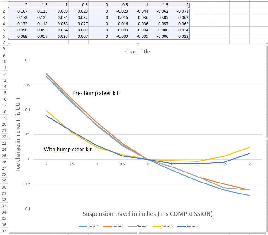
Here is the data that I have obtained using the Longacre bump steer gauge (MODIFIED UCA LOCATION).
I have moved the UCA back a little over an inch for caster gain, also dropped the rear mount a little over an inch for some anti-dive.
Series 1-3 are pre-installation of bump steer kit; Series 4&5 are after installation of the kit. Number across the top is compression (+) and rebound (-). Toe out is (+), toe in is (-).
After the bump steer kit, I really like my rebound #'s, but the compression #'s leave a lot to be desired. I actually installed the kit with zero shims, bringing the tie rod closer to the upright mount I believe (compared to standard tie rod end). Adding shims (ie dropping the outer tie rod) made a similar graph to the original tie rod end. This didn't make sense as adding caster raised the tie rod mount on the upright - seemed to me that I would have to bring it back down with shims?? Looks like I need to bring it up even higher, but I don't know how I can do that - or lower the rack.
I am now seeing toe out in both compression and rebound, which is significantly improved compared to before installing the kit.According to the Longacre technique guide, the cure for this is to shorten the tie rod. Does this sound correct? Do I basically need a rack extender? Thanks!
dave
Last edited by beeman; 03-29-2017 at 09:45 PM.
MK3.1 2004 Mach 1 donor. ABS, PS, TC.
GTM #304 LPE 525hp LS3
2000 C5 Lingenfelter LS1@489hp
1999 Corvette FRC/Z06 track car
-
Senior Member
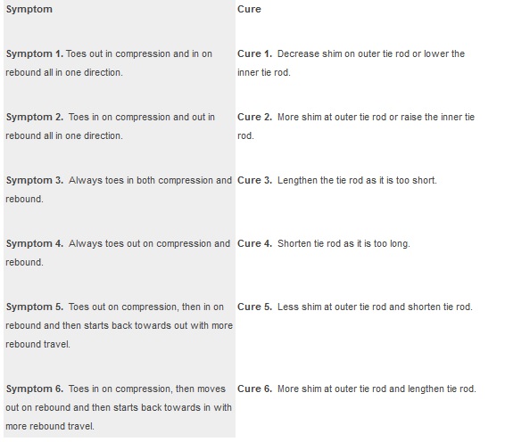
Per this chart, I have symptom 5.
Would you agree that I need to raise the outer tie rod? How can I do this since i am already running no shims? Lower the rack (With an offset bushing maybe)?
Looks like my tie rod is too long - would a rack extender fix this? Do they make one for our manual racks?
Thanks
Last edited by beeman; 03-29-2017 at 10:32 PM.
MK3.1 2004 Mach 1 donor. ABS, PS, TC.
GTM #304 LPE 525hp LS3
2000 C5 Lingenfelter LS1@489hp
1999 Corvette FRC/Z06 track car
-
Senior Member
OK, been thinking about this through the night.
Basically I want my ride height to be at the apex of the curve. This can be accomplished by (1) changing the ride height (2)raising the outer tie rod - I can't do this as it's already as high as it can go, or (3) lower the rack with an offset bushing.
To correct the out-toeing, the tie rod length needs to be effectively shortened. This will likely require the Flaming River rack extender kit. I will look at it again and shorten the tie rod temporarily by rotating the steering towards the side I'm measuring while maintaining the same toe. This will tell me how much tie rod shortening I need.
MK3.1 2004 Mach 1 donor. ABS, PS, TC.
GTM #304 LPE 525hp LS3
2000 C5 Lingenfelter LS1@489hp
1999 Corvette FRC/Z06 track car
-
-
Something to know...we try and get our bump steer dynamic down to a reasonable number, but more importantly, we want the bump steer to actually benefit what we are doing as far as car attitude and dynamic performance. In other words, bump steer is nearly impossible to make zero, but we can use that to our advantage by making the bump steer effect go into toe out under braking/turn in, and toe in under acceleration. This makes for a more aggressive turn in, and a more stable situation when accelerating down long fast straights. As long as, dynamically, you are not doing the opposite, you should be fine with those numbers.
-
Senior Member

Originally Posted by
FFinisher

Ha, thanks from all of us!
I went from knowing very little about bump steer yesterday morning, to receiving the bump steer gauge and doing a lot of reading. I'm starting to grasp it. It really helps to be there and see the dynamic toe with compression/rebound. I know my roadster has bump steer issues as well that I will need to tackle at some point.
Originally Posted by
crash
Something to know...we try and get our bump steer dynamic down to a reasonable number, but more importantly, we want the bump steer to actually benefit what we are doing as far as car attitude and dynamic performance. In other words, bump steer is nearly impossible to make zero, but we can use that to our advantage by making the bump steer effect go into toe out under braking/turn in, and toe in under acceleration. This makes for a more aggressive turn in, and a more stable situation when accelerating down long fast straights. As long as, dynamically, you are not doing the opposite, you should be fine with those numbers.
I was hoping you'd chime in, thanks.
So am I thinking I'm better off with the 'after' curve, but maybe my goal should be putting the ride height away from the apex of the toe curve? IE leave it where it is on the curve. I see people say avoid toe-in bump, but you think a little is OK on rebound?
Maybe keep the end link angle where it is, lengthen the rack only? That looks like it should give me a flatter toe curve but allow for a slight amount of toe-in with rebound.
Thanks!
Last edited by beeman; 03-30-2017 at 10:12 AM.
MK3.1 2004 Mach 1 donor. ABS, PS, TC.
GTM #304 LPE 525hp LS3
2000 C5 Lingenfelter LS1@489hp
1999 Corvette FRC/Z06 track car
-
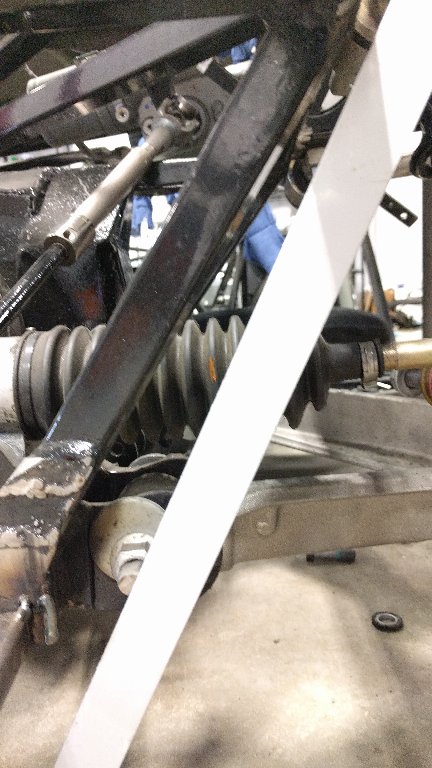
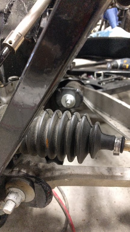
Senior Member
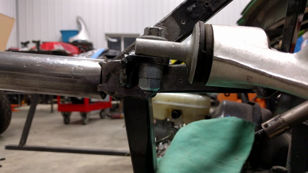
Here's a straitedge connecting the inner control arm pivot points. The orange mark on the rack boot is the inner tie rod location, looks like it's only about 1/2 to 3/4" too inboard. Flaming River makes rack extenders, but they come in 2" and 4" lengths.
MK3.1 2004 Mach 1 donor. ABS, PS, TC.
GTM #304 LPE 525hp LS3
2000 C5 Lingenfelter LS1@489hp
1999 Corvette FRC/Z06 track car
-
Because of the dynamics involved, your question is not an easy one to answer. For instance, we changed our shock package and now our car likes to stay a lot lower when it is driving, but static ride height is normal at around 4-4.5 inches. So you really have to look at where you are intending to operate and shoot for the correct geometry and changes from there, as opposed to just the static number. Unlike camber gain, it doesn't really effect the car nearly as much when you go thru the inflection point of toe. While you will certainly know if you get too much toe in or out, I have not really felt any ill effects from going thru the toe inflection point. We do set the toe at static ride height, obviously, but we also are aware that that is not necessarily where the system will be operating most of the time. Just be aware of the dynamics and guesstimate about where you are likely to be operating most of the time and make sure the numbers are not too extreme. What are those numbers? Tough to pinpoint in general terms, but you will know it if you reach the extremes as the car will fight itself and wander if TOO MUCH TOE IN is achieved, and will become very light feeling and wander if TOO MUCH TOE OUT is achieved. It is a balancing act that is unique to every car and every operating condition.
-
Originally Posted by
beeman
Here's a straitedge connecting the inner control arm pivot points. The orange mark on the rack boot is the inner tie rod location, looks like it's only about 1/2 to 3/4" too inboard. Flaming River makes rack extenders, but they come in 2" and 4" lengths.
Right idea, but remember that your suspension pivot points stay stationary and your rack pivot point moves as you change steering input. Again, this must be looked at in a dynamic way, not just static, and because of this change, you will never achieve a zero toe change number. NEVER.
-
Senior Member
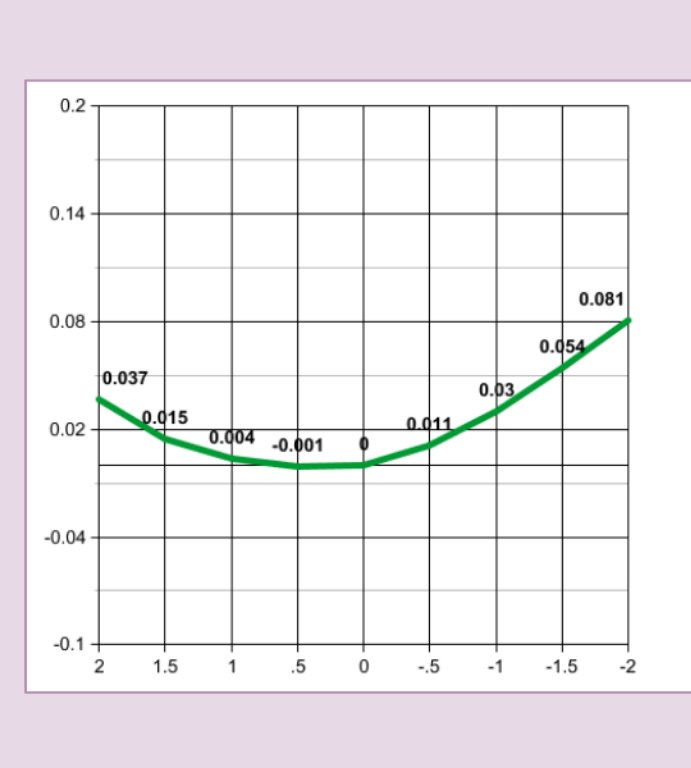
My thought is that most high speed driving is going to be with the rack centered, I should optimize that to avoid instability at high speed, right?
Here is where I am now, my compression numbers (left side of the chart) seem pretty good, and my rebound numbers look OK to 1" of rebound then drop off. Should I care as much about rebound travel as compression?
MK3.1 2004 Mach 1 donor. ABS, PS, TC.
GTM #304 LPE 525hp LS3
2000 C5 Lingenfelter LS1@489hp
1999 Corvette FRC/Z06 track car
-
I think you are going to be pretty happy with what you have there. The numbers do not appear to be drastic. I would not suggest knocking yourself out at this point trying to minimize or tune that further. You need to keep going on the building parts of this project! 
-
Senior Member
No kidding! I feel like I've taken a lot of steps in the opposite direction of the finish line, oh well.
It's amazing how a small tie rod shim or small change in LCA cam bolt position changes a 0.005" bump at 1" travel to 10x, ie 0.050".
Now that I know I can live with this, time to weld in the UCA mounts.
Last edited by beeman; 03-30-2017 at 03:19 PM.
MK3.1 2004 Mach 1 donor. ABS, PS, TC.
GTM #304 LPE 525hp LS3
2000 C5 Lingenfelter LS1@489hp
1999 Corvette FRC/Z06 track car
-
Senior Member

Your numbers look a lot better than mine.
Just an old man with a great hobby
-
Senior Member
Roger -
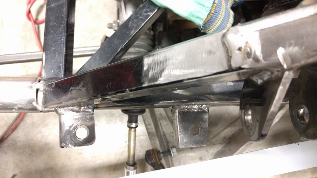
Here's where I put everything with that bump steer curve. I'm guessing caster about 7 degrees with some room in both directions. Camber with a digital angle gauge about 1.2 degrees at ride height, again with room for adjustment. UCA mounts as close to frame rail as possible (moved at least 1/8" inboard), now about 1/16" clearance. Have about 1" of anti-dive (maybe about 40% of C5 amount). Shimmed up and down with washers until I had the bump steer curve above, got worse with moving mounts up AND down. You might try measuring bump steer with moving your UCA up (and potentially down) with 1/8" washers to see if things get better. I do have a bump steer kit for my tie rod.
Goal of this was to accomplish the defeat of 2 things that could kill me - bump steer and lack of caster. I am running electric power steering it should be noted.
Last edited by beeman; 03-31-2017 at 08:55 PM.
MK3.1 2004 Mach 1 donor. ABS, PS, TC.
GTM #304 LPE 525hp LS3
2000 C5 Lingenfelter LS1@489hp
1999 Corvette FRC/Z06 track car
-
Senior Member
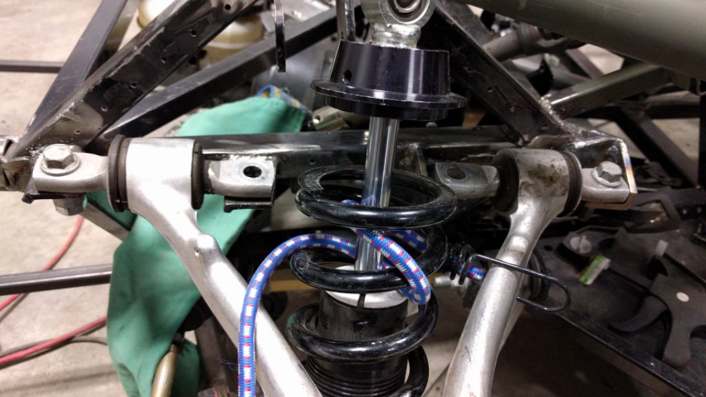
Corrected last post. Here's a couple pics.
Edit : should mention my front ride height is 4.5"
Last edited by beeman; 03-31-2017 at 09:25 PM.
MK3.1 2004 Mach 1 donor. ABS, PS, TC.
GTM #304 LPE 525hp LS3
2000 C5 Lingenfelter LS1@489hp
1999 Corvette FRC/Z06 track car
-
Senior Member
When I get back from vacation I will post my bump steer numbers.
Just an old man with a great hobby
-
Senior Member
Roger -
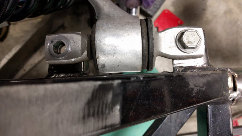
One other comment. The LCA cam design adds another degree of difficulty to getting the bump steer right. Changing the cam position effectively shortens and lengthens the lower control arm. This changes the intersection point /instant center of the suspension. Moving the cam bolt had a profound affect on bump steer. And changes in LCA length are hard to address with bump steer kits/shims, you would need to change the tie rod length to correctly address that. So I found a position of the LCA cam bolts that gave me a good curve and am going to keep them essentially there and accept the camber and caster I have.
So if your curve looks off, and you have some room with camber and caster, you could play with the cam bolt positions.
Here's where I have them
Last edited by beeman; 04-01-2017 at 10:03 AM.
MK3.1 2004 Mach 1 donor. ABS, PS, TC.
GTM #304 LPE 525hp LS3
2000 C5 Lingenfelter LS1@489hp
1999 Corvette FRC/Z06 track car
-
Senior Member
There is a forum member (Mike) that put together the proper combination of a arm parts effectively making his own upper control arm. This setup would allow caster change without welding the frame (not anti dive). It would also allow for a shorter or longer uca to, as you posted, change the position of the lower cam and the relative position of the steering rod pivot.
When I moved my uca mounts 1 inch rearward I also changed from a vertical bolt to a horizontal bolt like the corvette mount. I can add spacers to decrease camber (move the top out). I could then move the position of the lower control arm to recover my camber. This would result in a different relationship between the steering rod pivot and the upper and lower pivot points. Providing I have enough fender clearance under bump/turning conditions. If I were to make changes my first choice would be to modify the end of the steering rack either longer or shorter as required.
As it is now, my GTM has very good turn in manners.
I agree with the approach you are taking in sorting these things out before you get too far. I can't wait to see what you come up with next.
Just an old man with a great hobby
-
Senior Member
I am familiar with that custom UCA, I have been made aware that it is not currently available, but may become available in a few months. I am at a point in my build where I would like to start throwing the body on, and needed to know where my front wheels will be with the caster I desire. So I felt I needed to keep things moving. I still may find a reason to buy it if it does become available again, it really expands your options.
MK3.1 2004 Mach 1 donor. ABS, PS, TC.
GTM #304 LPE 525hp LS3
2000 C5 Lingenfelter LS1@489hp
1999 Corvette FRC/Z06 track car
 Posting Permissions
- You may not post new threads
- You may not post replies
- You may not post attachments
- You may not edit your posts
-
Forum Rules

Visit our community sponsor


 Reply With Quote