-
Matt's Gen2 65 Coupe Build Thread
I had my build thread on the other site, but now that I'm finished I decided that I'll duplicate the build thread on this site as well. I had posted my photos on photobucket, but now that they've eliminated 3rd party hosting, all the pictures don't show up, so I'm starting to slowly upload my pictures to the gallery here. That way the pictures will be with the site and hopefully will stay together with the build thread. It'll take a while to complete the process, but I figure if I do a little each day soon it will be finished. Bare with me and I apologize if it may seem funny when I write "today" for something that happened in the past, since a lot of this will be cut and paste.
We'll see how it works out and hopefully it will be helpful to people as their build their cars.
Thanks.
-Matt
-
Trip to Factory Five
In October 2013, my Dad, his friend and I took the 1.5 hour trip from Hubbardston, MA to Wareham, to take a tour of the Factory Five headquarters. A few weeks later I ordered up the 65 Coupe complete kit with IRS. In the time between when the kit was ordered and when I picked it up, I spent many hours reading this forum, ordering the Russ Thompson turn signal system and windows, mustang pedal box from Mike Everson, and steering rack and IRS and brakes from Mike Forte. Also spent time trying to understand the rules in MA on getting this car registered.
-Matt
-
-
Engine
After researching what it will take to get this car on the road in MA, it looks like there were 3 options for the engine:
1. Get a donor car and use engine and associated emissions from that car.
2. Get a pre 1974 car with a V8 that has been registered in the past 5 years and scrap it.
3. Get a pre 1974 engine and rebuild it.
This is all in theory as I haven't finished the car and gone through the process yet.
With that being said, I'm trying to go with option 3. I found a 1971 Ford Mustang at a junk yard in RI with a 302 in it. I called up and inquired about it and the person said the engine turned over when it came to them. It had been sitting outside in their yard for a bunch of years. I told them I'd take it. It was under a bunch of snow, so they said it would take a few days to pull it out. A few days later, I received a call saying that got the engine out, but it wouldn't turn over. He said he'd try soaking the cylinders with oil for a few days and see if that would help. Got a call a few days later saying, "nope, still wouldn't turn over". I figured oh well, it'll be a learning experience. I bought the engine anyways, loaded it up on my truck and took it home.
There was a picture of the car it came out of on the yard's website. The car looked in pretty good condition, which probably wasn't a good thing. I started thinking there are probably two main reasons a car is in a yard.
1. The car is totaled
2. There is something wrong with the engine or tranny.
We'll it wasn't reason 1, so it had to be reason 2. I was just hoping the block wasn't cracked.
Below are two pics of the car it came out of and a few of the engine on my truck.


-Matt
-
-
-
AC/Heater cont.
Here's a picture with the drain added below the AC hoses. This is connected with 2 - 90's and shoot's straight down inside the start of the transmission tunnel.

Everything associated with the AC/heater/drain hoses was very tight and just barely fit. Let's hope it actually works....
-Matt
-
-
Steering
When I installed the steering shaft it wasn't really centered in the hole in the dash. I then put on the steering wheel to see what that looked like. I noticed the wheel seemed a little high and also totally blocked the gauges. I decided to lower the wheel and center it a little better, so off with the old mount. Then I notched into the frame some to lower the shaft and wheel.
This is not the best picture, but you can see the notch in the frame to lower the wheel

Then I needed to create a new way to mount the pillow bearing. Ended up making some crazy mount, but it seems to work. Then you can see the Russ Thompson turn signal mount into the new piece.

Now the shaft was a little lower and better centered.
-Matt
-
-
-
-
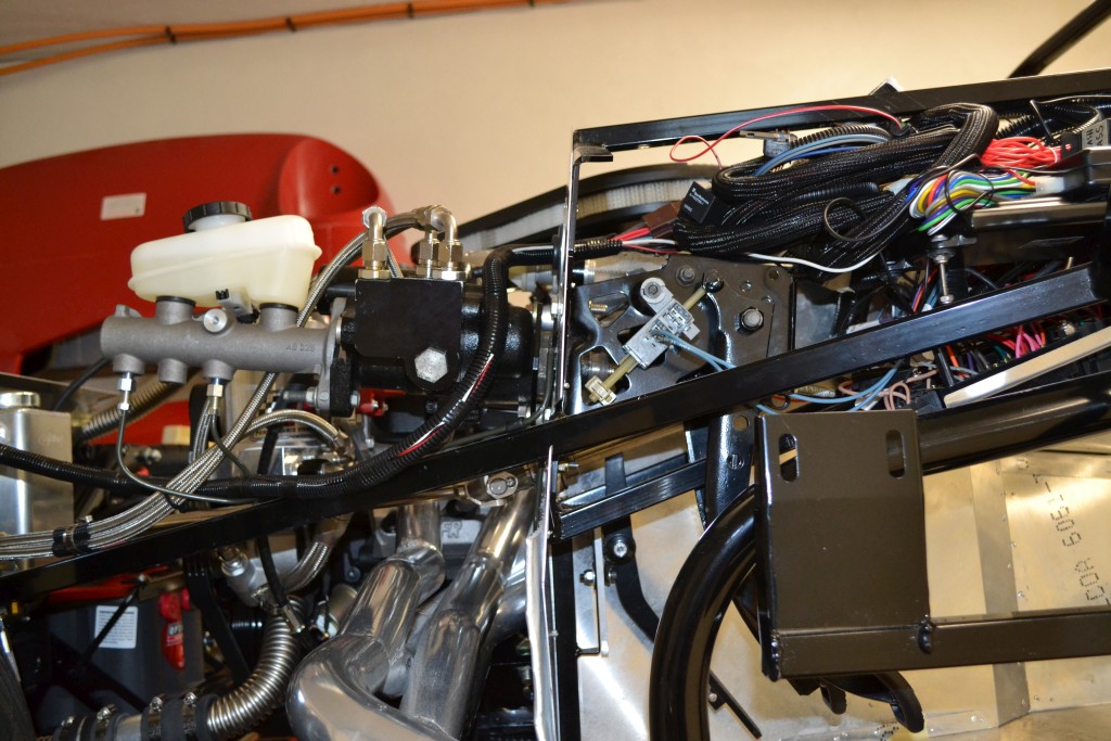
Pedal Box and Hydroboost
For the pedals I bought a 94+ Mustang Pedal box from Mike at replicaparts. When it came in the mail, it was perfect and looked better than new with everything freshly powder coated. I was planning on using hydroboost for power brakes. To mount the pedal box, there are 4 bolts which go through the firewall/metal and hold it tight. To mount the hydroboost, I had to take off the plate and use some of the spacers to space it properly. On one of the spacers my Dad welded a small tab to fit in the notch of the hydroboost to keep it from spinning. This spacer is held on with the hydroboost nut, then another spacer before the firewall and bolts through and sandwich the pedal box.
The hydroboost unit came from a 2004 Mustang. When I received the unit, the low pressure return fitting was broken off, with the thread part of it still in the aluminum block which bolts onto the hydroboost. I tried to remove what was still in the aluminum, but couldn't get it out. So over to my Dad's who has some bolt extractor bits. When we tried that, it wouldn't budge and would just strip the bit that was still in. Finally, we decided we would drill it out. As soon as we put the drill in, the piece came right out. It was a left hand thread! I couldn't imagine why they would use a left hand thread. Oh well, the piece was out. Next was trying to find a replacement, but I couldn't find any.
After much searching on the internet, I came across this post on the sn95 forum:
"*****Important note, there are differences in the Hydroboost units that you buy, so try to get them from the same car. On the 96-98 the 3 lines for the fluid all go into the unit, but on the 99-04 they have a separate aluminum block that bolts to the side of the hydroboost unit for one of the high pressure lines, and the low pressure return. ALSO I WOULD RECOMMEND NOT BUYING A UNIT FROM 2004, in 99-03 they aluminum block I just mentioned is perfect and can be changed to AN Hose easily, but on all Hydroboost units from the 2004 year they have a LEFT Handed fitting and you have to be careful not to strip it out. My unit was from a 2004, so I have mine machined to use right handed thread fitting adapters."
Once I found that post I decided to buy a -6AN to 1/2-20 o-ring fitting and drilled and tapped the aluminum piece for that.
The other two fittings I found adapters for -6AN.
For the brake master cylinder I got a Cardone Select 13-2937 Brake Master Cylinder.


-Matt
-
-
Power Steering
Going with power steering. Not sure if I need it or not, but thought it would be easier to put in while building, rather than try to add in later. This did complicate the build a bit going with hydroboost and power steering. Bought the rack from Forte's, then when I got the rack found out about the rack extension as well. Called up Factory Five and ordered those as well. Next was the connections, got the adapters to -6AN from Breeze. Then of course more reading on this forum and more spending money, had to have a cooler as well. Got the Derale -13310 cooler. The rack was fairly straight forward to put in, but required a bunch of tweaking to center it and the steering wheel. Once I got that all set, then I need to cut the tie rods a bit as they were too long.
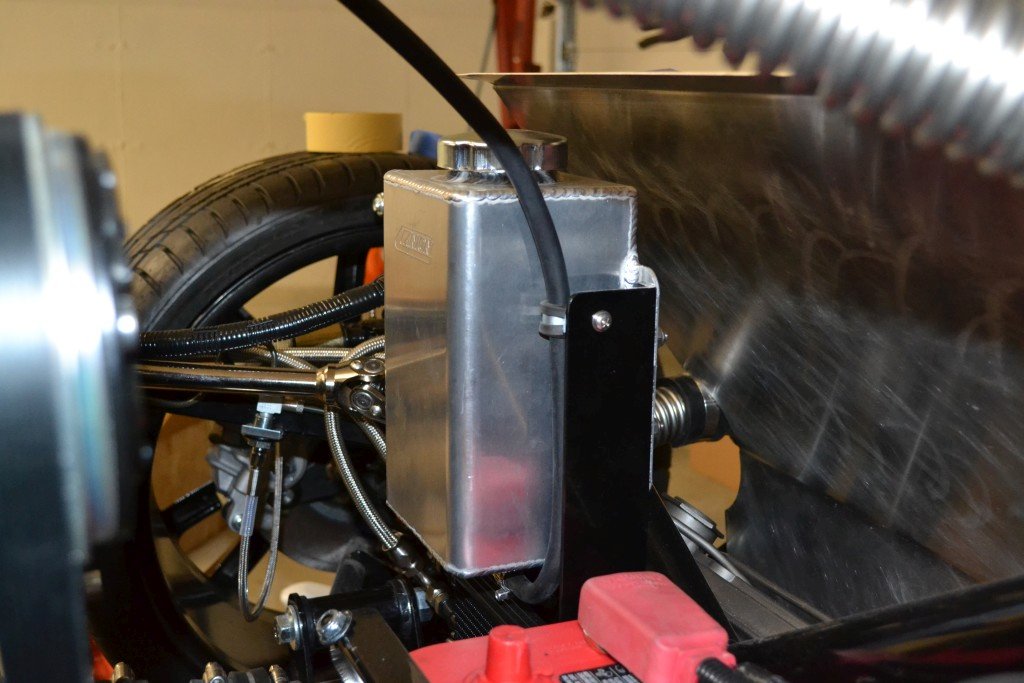
Next was the power steering reservoir. For that I got the PSC 8.25" Pro Touring P.S. Remote Reservoir w/ Filter For Hydro Boost Brakes Brushed Aluminum. It just kept getting more complex and expensive. I was in too deep to turn back now, just need to figure out how to mount and connect all of this together. I made a few more pieces from aluminum and mounted the reservoir right above the pump and it just fit.
So I started drawing some diagrams and figuring out the adapters and hoses that I needed. I'd spend a little time every night refining it, "if I use a 90 here, then I'll need a straight here", "if I route this hose here, then this one will go here", etc. Ok, enough planning, time for some "doing". I ordered up the hose got 10' Russell 632640 -6AN power flex hose, 8 - 90's and 2 - straight ends. Then I started making hoses. Read a little on the internet how to make them and it wasn't too bad. Well I haven't tested them out yet, so I can't say for sure if I did them correctly. Slowly it started to come together. I got lucky that the 90's just fit on the rack and between the X of the frame and still could get a wrench on them. Looped around to the cooler which I mounted to the X frame, then to the pump.
Reservoir

Reservoir also doubles as coil mount.


cooler mounted


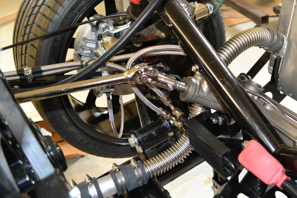
90's just fit.....

-
-
Post Thanks / Like - 0 Thanks, 1 Likes
-
-
-
-
-
Coolant Lines Cont.
Now zooming back out.

-Matt
-
Recovery Tank
For the coolant recovery tank, I bought the Canton Racing Products 80-201 2 Quart Aluminum Recovery Tank. I mounted this to the left of the battery and over the power steering cooler.
I made some metal mounts out of aluminum angle and shared some of the mounting points with the cooler and battery box.

-Matt
-
Electric Fuse Box
The electric. At first I thought it would be hard with all the sensors, wires, etc. Then I thought it would be easy since I have the wiring harness with the complete kit and it should just be plug and play. Well, my first thought was correct. It's not that it is that hard, just very time consuming. I spent a lot of time looking over the schematics and trying to draw up my own. I really wanted to understand where all the wires went and not just plug it in and hoped it all worked.
The first thing I did was to mount the fuse box. This I did in the recommended spot under the steering shaft.

Then once it was mounted I tried to trace all the wires going to the fuse box and see where they got their power. I wanted to know whether it was powered from the battery feed, ignition feed or the accessory feed. The schematic in the manual didn't show that detail. Below is a picture that I drew up with the location of the fuses and the wiring to each fuse.

Once I had that information, I could start drawing up the full schematic of how I would connect everything to the fuse box. I redrew the fuse box and added in some additional labels.

Then I put together this sheet with how I would wire in the power to the fuse box. I also show how I wired up the battery, alternator, key switch going to a 12V distribution point.
At the bottom of the page I have the head light switch.

That's about it for the basic wiring diagrams. I'll add in more later showing the turn signal, hazard lights, backup lights, cameras and fog lights.
-Matt
-
Heat Shield
Before I installed the engine, I wanted to put some heat shielding along the foot boxes and the firewall. I bought some Zero Clearance Aluminum/Fiberglass/PSA Insulation from Breeze Automotive. First I made some templates with brown packing paper, then when I was happy with that, I started cutting up some pieces. I mainly uses scissors to cut it, but it wasn't easy to cut. I then peeled off the backing and stuck the pieces on. In some cases also added rivets with washers on them to make sure the pieces stayed on.
Here you can see where I added it. I also ran it down the inside of the transmission tunnel a bit.

You can also see some of the wiring that I talked about in the last post between the passenger motor mount and foot box. I ran a + and - from the battery to the starter, then a + and - to the fuse box.

I still plan to put a piece on the top of the passenger foot box and the driver side once I get those panels installed.
-Matt
-
-
Side Pipes
When I first received the kit I took out the side pipes and figured I'd better paint them before they got rusty. I didn't know how long it would be before I'd have a chance to use them. I brought them to my Dad's house and bead blasted them clean. I then used some high heat primer on them. Then followed that up with a couple of coats of Rust-Oleum High Heat Ultra "Semi-Gloss" black paint. I don't know how well it will last, but figured I could easily touch it up later if I had to. Also wanted to go with black to match the black wheels.
I wanted to get the pipes on for the first start to see how loud it will be with these. I thought it might be tight fitting them on. I went to put the driver's side on and try to slide them on the header. Nope, wouldn't go. I jammed wood shims in the headers and a clamp on the muffler to bring the two pipes closer so they would fit. Nope. Ok, let me try one of the two pipes onto one of the header pipes. Nope, not even close. Time to start grinding, sanding, filing, dremeling, etc. At this point I didn't care about scratching anything, I just wanted to be able to slide the pipes on. Finally after a few hours of taking a little bit off at a time of both the outside of the header and the inside of the mufflers, I was able to slide the driver's side on. Put on the clamps and called it a night. The passenger side would wait until the next night.
Time for the passenger side. Looking at the two pipes of the muffler for the passenger side, I could see that the metal at the end was much thinner on one of the two pipes. That side would easily slide over the header. The other one was the same thickness as both of the driver side pipes. This needed grinding to fit on, but at least I was prepared for it this time. I ground away and was able to get this side on much easier. Put the clamps on and went to bed.
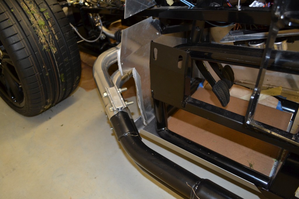
Back to the drivers side, the header was slightly touching the corner of the driver's foot box. To gain more clearance, I cut the footbox and bent it in. I still need to make the outside piece fit, and will get to this soon.
Here you can see the cut in the footbox that I needed to make (as well as the grass still on the tires from my first go kart) to provide clearance for the header. Since my foot could never get in that corner, it shouldn't really impact the room in the footbox.:
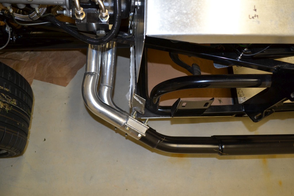
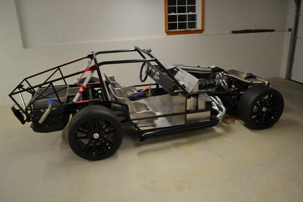
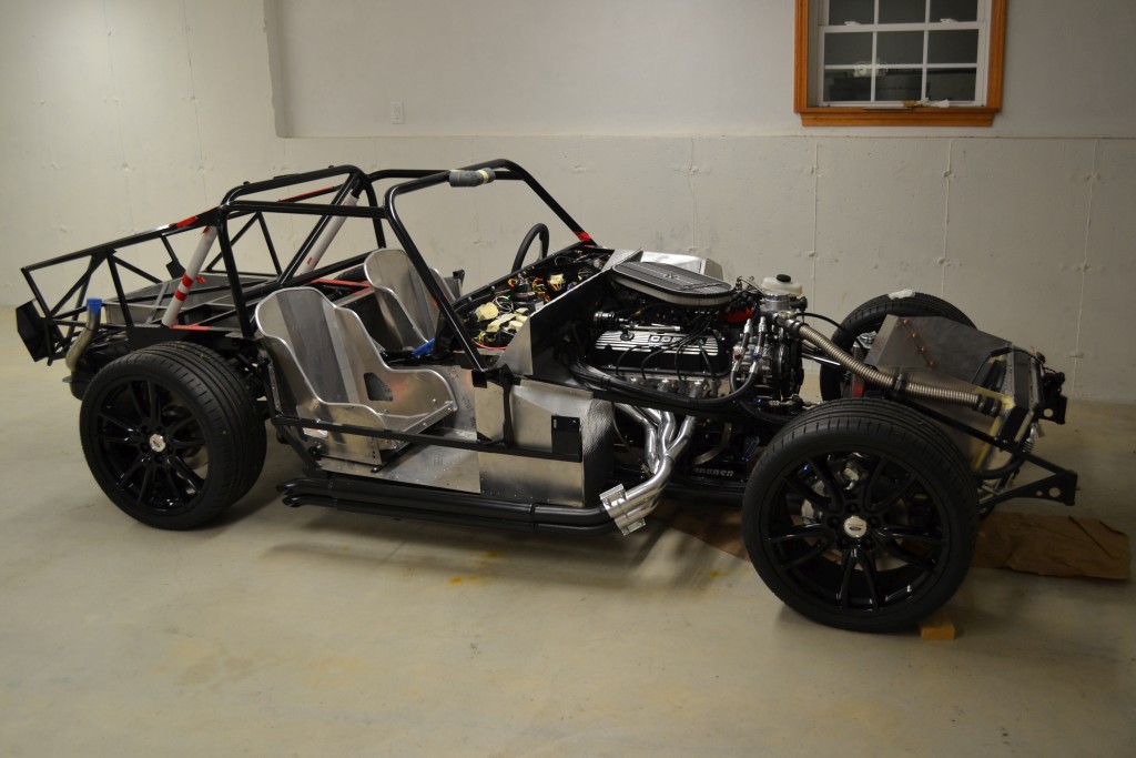
Here are a couple of pics of the passenger side of the car showing the black pipes and how the car sits now:
I didn't install the hangers yet and will wait to do this after the body is on.
-Matt
-
Hazard and Turn Signals
Back to the electric and the hazard switch and turn signals. For the hazard switch, I used the ON-ON double pole switch from the kit. For the turn signal, I was using the Russ Thompson turn signal. It took a bunch of research to figure out how I wanted to connect it up. Eventually I settled upon the following schematic:
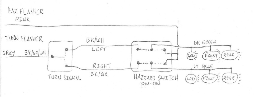
Normally, the hazard switch will be in the down position (connecting left to middle in the above picture), which connects the turn signal path. The middle connection of the hazard switch goes to the dash LED and front/rear lights for each side. Then the turn signal will function.
With the hazard switch in the up position (connecting right to middle in the above picture), the turn signal will be bypassed and since the hazard flasher connects to both the left and the right side of the switch, both sides will flash.
-Matt
-
-
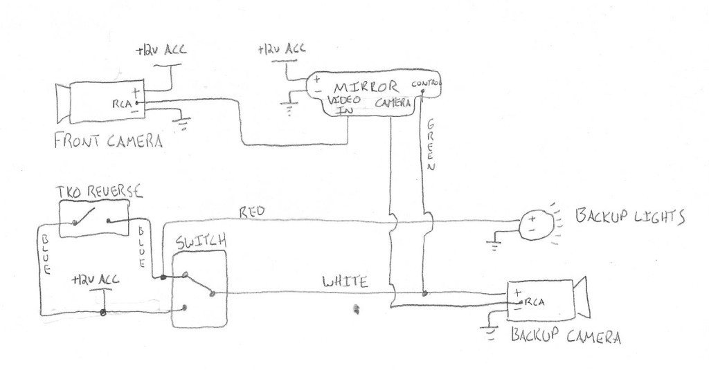
Front and Backup Cameras
I wanted to have a backup camera on the car since I figured it would probably be difficult to see out the back. Then I decided, why not a front one as well? I spent a bunch of time trying to research different ones as well as how to display the pictures.
I decided that I wanted to use the rear view mirror to display the cameras. I ended up getting the CrimeStopper SecurView SV-9156.CT. This has a 4.3" LCD Screen, Compass and Thermometer and has 2 inputs.
For the cameras I got 2 PyleView PLCM38FRV cameras which can be used as a forward or a reverse camera (ie. flip image). There are 3 wires on the camera that can be tied together to reverse the image and show distance lines. For now I have the distance lines off and the rear camera reversed.
Now for the fun part, hooking them up. Again back to the pencil and paper to map out the connections. I wanted the backup camera to turn on when in reverse, so I needed to use the reverse switch on the TKO500. To connect to that I bought the Ron Francis Wiring Transmission Backup Light Connector Pigtails PG-055. I also added in a manual override switch to turn on the backup camera when I wanted, while not in reverse. So I can see who's tailgating me. :) I didn't want to turn on the backup lights when using this manual override switch, so I can use it while driving and not have the backup lights turn on. This required me to connect it via the schematic below.
The front camera will be powered all the time and the display can be turned on/off by a button on the mirror. So when the ACC is on, the front will display. If in reverse or I override it, the back will display.
There's a green wire on the mirror that when at +12V will display the backup camera, so this had to be wired in.
For the backup lights, I bought 2 Marker Lights - L488-Clear from Finish Line Accessories which match the Factory Five tail lights.
Here's the schematic:
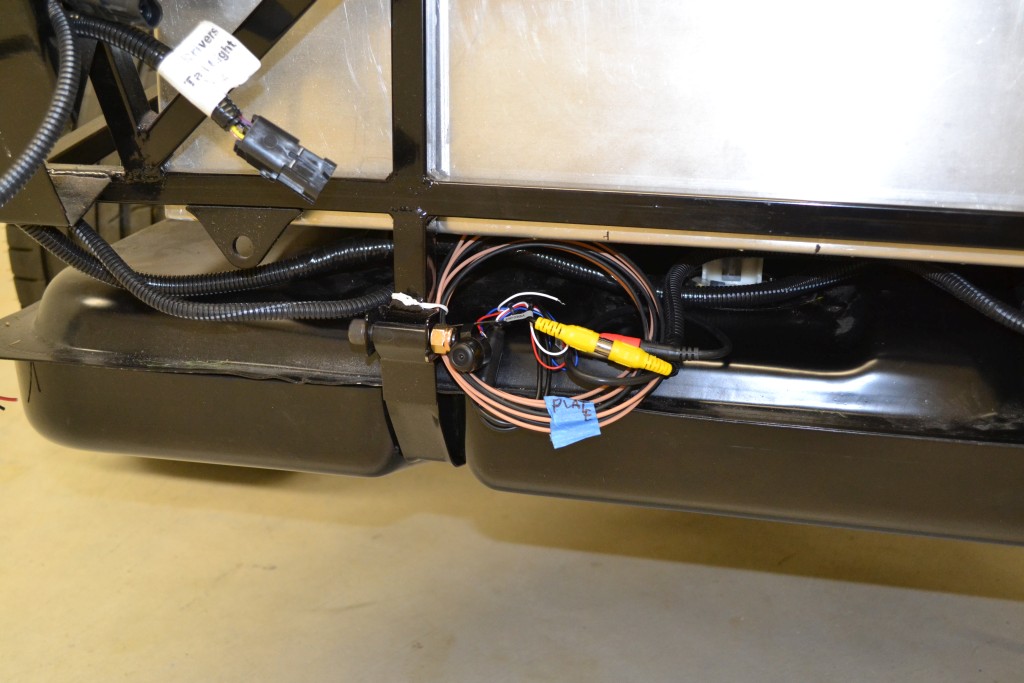
Backup camera (not the final mount):
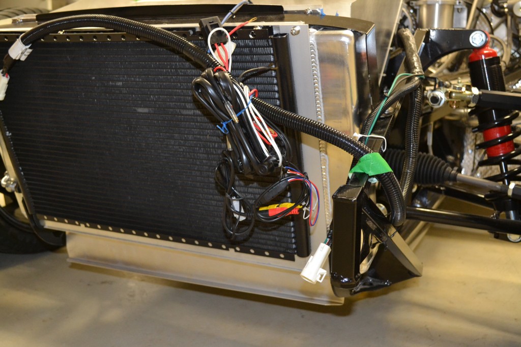
Front camera (not the final mount):
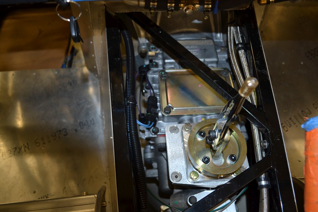
TKO pigtail. Hard to see.
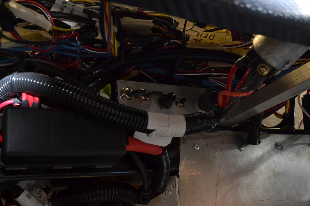
Override switch under the dash. The switch on the left is the backup camera override. Next to that is the radiator fan override switch, the dash dimmer, clock set button and AC temp knob.
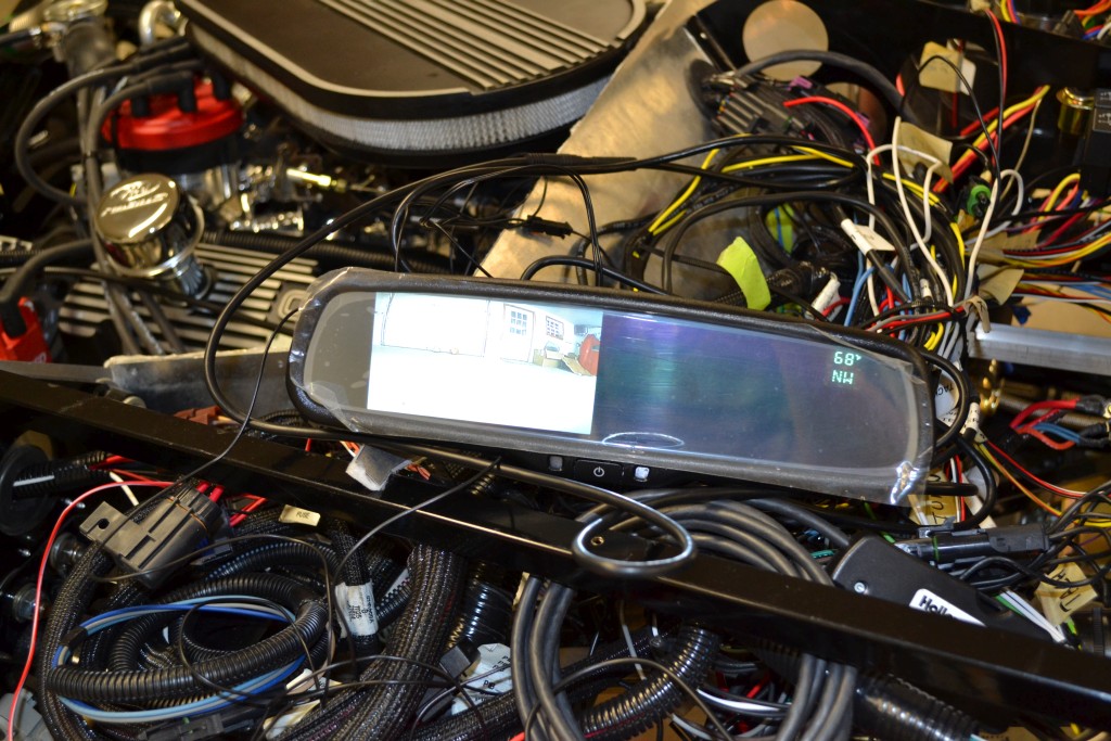
Here's a picture of the mirror showing the front camera. Also has the direction and the temperature.
Lastly, I had to make a video to show it in action. Enjoy. :)
-Matt
-
-

Steve >> aka: GoDadGo

So Totally Cool!
Congratulations On This HUGE Milestone!
-
-
-
-
-
Looks great. Re-welding the headers seems to be a rite of passage for Gen 1 and 2 coupe builders, from what I can tell. Carry on!
-
-
-
-


 Thanks:
  Likes:


 Reply With Quote
