BluePrint Engines

Visit our community sponsor

Thanks Thanks:  0
Likes Likes:  0
Page 3 of 4 FirstFirst 1234 LastLast
Results 81 to 120 of 160

Thread: Custom Body - Methods and Means - Software, Programs and Techniques

  1. #81
    Banned
    Join Date
    Mar 2011
    Location
    San Diego CA & Cave Creek AZ
    Posts
    294
    Post Thanks / Like
    Fabric surfaces are necessarily limited to flat sections, with the exception of areas where heat shrinking will pull it to a subtle hyperbolic paraboloid.
    Finishes can vary from matte to high gloss.
    Weight should be minimal, especially if aluminum tubing is used.
    In a few places, fiberglass parts would be used (windshield surround, side scoops, etc.). The interior close-offs including wheel houses would also have to be hard materials. Windshield is based on general measurements of a Chevy Aveo.
    This rear engine design would allow for 2+2 seating. OAH is at 46”, a little less than the FFR template but reasonable.
    SSS4.jpgSSS3.jpgSSS5.jpgnewtubesA.jpg
    Last edited by olpro; 08-30-2011 at 10:09 PM.

  2. #82
    Senior Member kach22i's Avatar
    Join Date
    Mar 2011
    Location
    Michigan
    Posts
    894
    Post Thanks / Like
    Quote Originally Posted by olpro View Post
    This rear engine design would allow for 2+2 seating.
    There are several cases of Subaru engines now powering 912's and 911's (formerly air-cooled variants), is this the same type of installation you had in mind?

    I really like your design, something about how clean and simple it looks, and with little adornment is appealing to me.
    Last edited by kach22i; 08-31-2011 at 06:32 PM.
    George; Architect, Artist and Designer of Objects

    1977 Porsche 911 Targa, 2.7L CIS Silver/Black, owned since 2003
    1998 Chevy S-10 Pick-Up Truck 4x4 4.3L V6 Black with front and rear spoilers
    1989 Scat II HP hovercraft with Cuyuna two stroke ULII-02, 35 hp with experimental skirt and sound control

  3. #83
    Senior Member crackedcornish's Avatar
    Join Date
    Feb 2011
    Posts
    306
    Post Thanks / Like
    Quote Originally Posted by olpro View Post
    This rear engine design would allow for 2+2 seating.
    SSS4.jpgSSS3.jpgSSS5.jpgnewtubesA.jpg
    and wheelies!

  4. #84
    Banned
    Join Date
    Mar 2011
    Location
    San Diego CA & Cave Creek AZ
    Posts
    294
    Post Thanks / Like
    http://mendeolamotors.com/motors/ind...d=1&Itemid=103
    I understand they have achieved about a 45-55 weight distribution with this arrangement. I wouldn't try a (heavier) six but the turbo fours would be fine, the car pulling over 1g in the corners. Remember a Meyers Manx once cleaned up at Pikes Peak, beating everything else. I don't know what powered it.
    On dune buggies, wheelies are cool but not probably on the road... In any case, this arrangement seems to have worked out okay for the 911, for years and years in racing.

    By the way George, thanks for the nice comments.
    Last edited by olpro; 08-31-2011 at 04:25 PM.

  5. #85
    Banned
    Join Date
    Mar 2011
    Location
    San Diego CA & Cave Creek AZ
    Posts
    294
    Post Thanks / Like
    Here is an earlier pix with a rear occupant in place.
    Although this is a possibility, I would never suggest it other than in an emergency. For one thing, it seems inconsistent to have 2+2 seating in a roadster with no doors/ hop over the side access.
    SSmidRayT.jpg. Second, in any version with weather protection, it is (obviously) not going to work out very well for the sap in the back

  6. #86
    Senior Member bromikl's Avatar
    Join Date
    Feb 2011
    Location
    Milwaukee, WI
    Posts
    378
    Post Thanks / Like
    Quote Originally Posted by olpro View Post
    Here is an earlier pix with a rear occupant in place.
    Without being able to see through the body, it looks like the driver has bookoo leg room and the passenger is riding the engine. With the 95 inch wheelbase, a 2+2 should be possible, but the driver will need to move forward quite a bit.

    Do you have a transparent image or frame view?
    Last edited by bromikl; 08-31-2011 at 05:43 PM.

  7. #87
    Senior Member kach22i's Avatar
    Join Date
    Mar 2011
    Location
    Michigan
    Posts
    894
    Post Thanks / Like
    George; Architect, Artist and Designer of Objects

    1977 Porsche 911 Targa, 2.7L CIS Silver/Black, owned since 2003
    1998 Chevy S-10 Pick-Up Truck 4x4 4.3L V6 Black with front and rear spoilers
    1989 Scat II HP hovercraft with Cuyuna two stroke ULII-02, 35 hp with experimental skirt and sound control

  8. #88
    Senior Member mekeys's Avatar
    Join Date
    Apr 2011
    Posts
    170
    Post Thanks / Like
    Blog Entries
    4
    Hurray finally started posting pictures of the 700 ,First batch up today..

  9. #89
    Banned
    Join Date
    Mar 2011
    Location
    San Diego CA & Cave Creek AZ
    Posts
    294
    Post Thanks / Like
    Quote Originally Posted by bromikl View Post
    Without being able to see through the body, it looks like the driver has bookoo leg room and the passenger is riding the engine. With the 95 inch wheelbase, a 2+2 should be possible, but the driver will need to move forward quite a bit.

    Do you have a transparent image or frame view?
    This layout drawing shows the driver in the full rearward position, with the rear passenger crammed in. These both are American 50th percentile manikins but front legroom is consistent with a 95% manikin.
    Obviously, with a 2+2 seating package, the front occupants can be expected to track their seats forward a bit, especially if there are adults in the back.
    The SAE manikin is not set up to show that people can spread their legs a little to avoid the seat in front of them – so there is some interference with the seat (if it were shown). Also the Beetle pedal position could be modified to improve the legroom situation.
    Please be assured that I would not consider this a decent four place package. On the other hand there are cars out there like this - I have been stuffed in the back of some of them .
    SSS6.jpg

  10. #90
    Senior Member bromikl's Avatar
    Join Date
    Feb 2011
    Location
    Milwaukee, WI
    Posts
    378
    Post Thanks / Like
    I may be mistaken, but if that's a Subaru engine/transmission back there, isn't it facing the wrong way? What did I miss?

  11. #91
    Banned
    Join Date
    Mar 2011
    Location
    San Diego CA & Cave Creek AZ
    Posts
    294
    Post Thanks / Like
    This one is done on a Beetle pan, rear engined not mid. The Subaru would be driving a beefed up 091 VW bus transaxle. Of course the engine and trans are faked because it is impossible to get a decent drawing of either.

    Post 81: '.... This rear engine design would.....'
    Last edited by olpro; 09-01-2011 at 08:28 AM.

  12. #92
    Senior Member kach22i's Avatar
    Join Date
    Mar 2011
    Location
    Michigan
    Posts
    894
    Post Thanks / Like
    Is that a radiator up front?

    What's it for?

    I love the overlay, grid background and all.
    George; Architect, Artist and Designer of Objects

    1977 Porsche 911 Targa, 2.7L CIS Silver/Black, owned since 2003
    1998 Chevy S-10 Pick-Up Truck 4x4 4.3L V6 Black with front and rear spoilers
    1989 Scat II HP hovercraft with Cuyuna two stroke ULII-02, 35 hp with experimental skirt and sound control

  13. #93
    Senior Member crackedcornish's Avatar
    Join Date
    Feb 2011
    Posts
    306
    Post Thanks / Like
    Quote Originally Posted by kach22i View Post
    Is that a radiator up front?

    What's it for?

    I love the overlay, grid background and all.
    it's still using Subaru power, so it still needs a radiator

  14. #94
    Senior Member kach22i's Avatar
    Join Date
    Mar 2011
    Location
    Michigan
    Posts
    894
    Post Thanks / Like
    Quote Originally Posted by crackedcornish View Post
    it's still using Subaru power, so it still needs a radiator
    I thought it was both a VW Beetle pan, and engine.

    Thought it could be an oil cooler, or A/C condenser.

    http://mendeolamotors.com/motors/ind...news&Itemid=27

    I see Ford and Chevy engines listed in the link above, not what I expected.
    Last edited by kach22i; 09-01-2011 at 12:01 PM.
    George; Architect, Artist and Designer of Objects

    1977 Porsche 911 Targa, 2.7L CIS Silver/Black, owned since 2003
    1998 Chevy S-10 Pick-Up Truck 4x4 4.3L V6 Black with front and rear spoilers
    1989 Scat II HP hovercraft with Cuyuna two stroke ULII-02, 35 hp with experimental skirt and sound control

  15. #95
    Senior Member kach22i's Avatar
    Join Date
    Mar 2011
    Location
    Michigan
    Posts
    894
    Post Thanks / Like
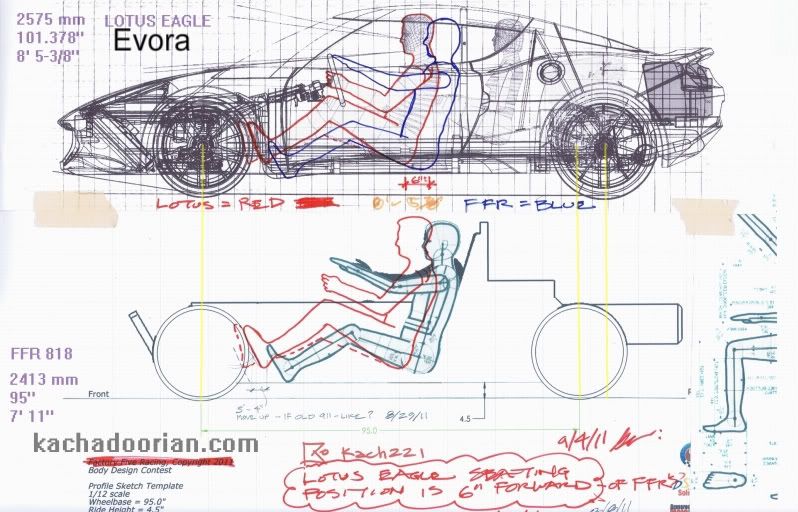
    I just wanted olpro to see this template work I've played with.................should be at least a little interesting to him.

    http://s184.photobucket.com/albums/x...rial%20Design/


    EDIT: Here it is without my mark-up mucking it all up.
    http://s184.photobucket.com/albums/x...2i/Automobile/
    Last edited by kach22i; 09-04-2011 at 07:46 PM.
    George; Architect, Artist and Designer of Objects

    1977 Porsche 911 Targa, 2.7L CIS Silver/Black, owned since 2003
    1998 Chevy S-10 Pick-Up Truck 4x4 4.3L V6 Black with front and rear spoilers
    1989 Scat II HP hovercraft with Cuyuna two stroke ULII-02, 35 hp with experimental skirt and sound control

  16. #96
    Banned
    Join Date
    Mar 2011
    Location
    San Diego CA & Cave Creek AZ
    Posts
    294
    Post Thanks / Like
    Thanks George.
    I had been looking for a seating package like that. The ones I had were all much higher (what would you expect from production Nissans?). In lowering my manikin, I had to fake the steering wheel location and forward vision lines, which that package includes.
    It also shows a good radiator location.
    Last edited by olpro; 09-18-2011 at 04:07 PM.

  17. #97
    Senior Member kach22i's Avatar
    Join Date
    Mar 2011
    Location
    Michigan
    Posts
    894
    Post Thanks / Like
    DIY CNC Router with Downloadable Drawings
    http://www.grabercars.com/content/view/67/2/
    These cnc router plans are free no strings attached. See below if you want the original files in either Solidworks or IGES format.

    This information has been COPIED here from a popular thread in my Grabercars forum. The CAD plans to build your own cnc router table are being made available to the general public for free.

    If you want to see some photos of what Jim has built so far, please visit Image Gallery Here . Hopefully I will be able to update with more photos as Jim gets them to me.

    Jim from Australia writes:
    I use a CNC 5-axis router for making Foam Plugs. The machine is scratch built and the cutting area is 3m * 3m * 2m. I use the machine for building aircraft and boat molds. All up it cost me about $3000 AUD ($1500 US) to build. The router is a classic Gantry style unit. The slides are made using 2 pieces of equal angle to form an X with bearings between them. The XYZ axis is driven via a threaded rod suspended on each end with a pillow block bearing. I machined the threaded rod to attach a sprocket and ran a chain drive to a stepper motor. The router motor is a 17turn RC car motor running on 12V with a PWM speed control.
    CNCRouter1.jpg
    George; Architect, Artist and Designer of Objects

    1977 Porsche 911 Targa, 2.7L CIS Silver/Black, owned since 2003
    1998 Chevy S-10 Pick-Up Truck 4x4 4.3L V6 Black with front and rear spoilers
    1989 Scat II HP hovercraft with Cuyuna two stroke ULII-02, 35 hp with experimental skirt and sound control

  18. #98
    Senior Member kach22i's Avatar
    Join Date
    Mar 2011
    Location
    Michigan
    Posts
    894
    Post Thanks / Like
    I'm told this skin is ordinary 3M window film, I'll have to verify that later. Take a look, it's pretty cool.

    http://minddrive.org/
    George; Architect, Artist and Designer of Objects

    1977 Porsche 911 Targa, 2.7L CIS Silver/Black, owned since 2003
    1998 Chevy S-10 Pick-Up Truck 4x4 4.3L V6 Black with front and rear spoilers
    1989 Scat II HP hovercraft with Cuyuna two stroke ULII-02, 35 hp with experimental skirt and sound control

  19. #99
    Banned
    Join Date
    Mar 2011
    Location
    San Diego CA & Cave Creek AZ
    Posts
    294
    Post Thanks / Like
    A very interesting site and projects.

  20. #100
    Banned
    Join Date
    Mar 2011
    Location
    San Diego CA & Cave Creek AZ
    Posts
    294
    Post Thanks / Like
    I was going to create a new thread for this subject but, since it is really about the “design process”, I thought it would fit into this already existing & informative thread started by George. I hope that is okay.

    (This post contains a lot of fussy detail and may be very boring for many people. On the other hand, if you are having trouble sleeping, this may be perfect for you)
    ---------------------------------------------
    The FFR templates have been a subject of much discussion, some of which was leaning toward minimizing their importance and ultimately their value.
    I have taken the opposite view, that indeed the templates were essential to a quality result and, if anything, they were too vague and flexible. This post is an attempt to address this subject in detail, NOT as an argument but simply as an explanation of this thing here called a “template” and how it generally works in the industry’s design processes.

    First of all, in the industry, the common term would be ‘layout drawing’ or ’LO’ drawing (‘template’ actually has a specific and different connotation – which is somewhat in contradiction to the FFR desire to not inhibit the designers in their efforts).
    The layout drawing (also called the ‘package’) is the responsibility of the engineers who are defining the project in terms of components, sizes and general seating, etc. It would include wheel locations, wheel and tire options, various ride heights (design, curb, show room, etc.) These last items will result in the ‘ground’ line being shown in several different positions and attitudes. Static load ratings on the tires relates to the different ground planes because tires ‘squish’ differently. This is important to show when considering the stance of a design relative to the world, as well as a factor in wheel/body clearances which might also be shown on the LO.
    Bumper heights and offsets, lamp heights, ramp angles, etc. are all related to the ground planes. Variations in wheels, tires, bumper systems and ride options can play hell with these height sensitive requirements.
    Mechanical clearances are shown with regard to the selected engine(s), suspension parts, radiator, fuel tank and fillers, and so forth. Luggage space and air openings may be shown, in terms of desired locations and areas.

    THE major concern of a LO is the people who must fit in the vehicle. Engines and suspensions can be redesigned but not people. Of course the LO engineers can select the specific people they want to ‘package’. This is usually done with respect to sex, percentile and sometimes even racial characteristics (i.e. 95% American Male, 50% Japanese Female, etc.). Also keep in mind that a 60% tall man can have a 75% torso length and 30% legs, etc. It gets complicated. The nature of the vehicle sets the seating package because of age, entry/exit requirements, etc. A sports car designer can assume things a passenger car designer cannot, in terms of seating issues. A sporty sedan or coupe will be done with the assumption that the folks in the back seat are not wookies. A good LO drawing will show not only the seating positions but maybe entry-exit envelopes. It may show ‘reach’ issues such as shifters (automatics and the various manual options, maybe even 4WD shifters – all shown in their multiple positions), dash controls and certainly steering. It will show vision requirements for gauges, mirror locations, direct forward and rearward vision angles. It will show head clearance bogies for header and headliner, usually for the different sized occupants. If engineering sections are available, showing the welded steel box section for a windshield header for example, this will be shown and how it affects the head clearances. Much of this relates primarily to interiors but exteriors are impacted.

    The basic reference point for the seating manikin is the H-point (hip point) and everything is related to this. Seat heights to the floor & ground planes, back angles, etc. are all measured from the H-point. Since most vehicles have sliding seats, the H-point is shown at different places. Normally the seat track slopes down at the back so the taller driver (who probably has longer legs) will be lower to the floor, preserving headroom for him/her.
    Most LOs I have seen will have special factors shown, according to the specific design program. Often this has to do with Carry Over parts because most programs are not all new from the ground up. Door handles, etc. can be moved around but each has its own maddening little requirements and clearances.

    With the advent of computer drafting, it is easy to select whatever lines on whatever components the LO engineer wishes to include on the drawing. The designer doesn’t want all the lines & info but it is time consuming to edit out the critical edges of a strut tower so the engineer shows the whole thing and the drawing starts to look like a big hairball.
    A lot of the engineer/designer negotiations have to do with the clearances that are required. A hood must clear the battery but by how much? What is an acceptable space for an assembly worker (or owner) to install a bulb? These things usually affect the exterior surfaces of the car.
    The government in its wisdom has not simplified the design process. Many things are the result of some Senate committee or bureaucratic agency responding to some specific issue. A child was run over at a stop light in Japan because a SUV driver didn’t see him. The result was a complicated set of vision requirements - mandatory in Japan but, because of import-export issues, also affecting the world. Severe European standards for pedestrian safety must be accommodated everywhere if the product might be sold worldwide. Various states may even have specific needs, not necessarily in the law but still worth knowing about (i.e. rear glass fouling in bad weather climates).
    On a production car, particularly a front drive, the cowl is the most complicated and fought over area on the LO drawing. Cross car structures, HVAC, engine bay parts, instrument panel components, windshield mounting & wiper locations are all competing for space. A high cowl which is jammed back toward the driver is a bad, bad thing for appearance, especially when combined with a windshield header location that is high and forward and little wheels. The high cowl results in a high H-point and roof. The cowl is not only the most complicated area on these cars, it is the most critical to design appearance. If ignored during initial design selection, the chickens will come home to roost later and the car will be a toad.

    A basic feature of the LO drawing is the reference system - which is a numerical grid with assumptions on what is ‘level’ and what are the ‘zero’ points from which to measure. This varies from company to company but often the zero line for up-down measurements is around (and parallel to) the SILL of the vehicle. This is usually called the Z axis. The side to side reference (Y axis) is the longitudinal centerline. The fore-aft reference line may be at the front wheel centerline - or maybe a point forward of the front bumper (this latter approach is intended to keep measurement numbers positive). The ground line is never parallel to the grid or at least it seems that way. The grid provides a universal measurement system for all engineers and designers and is indispensable throughout the process, from concept to collision repair.

  21. #101
    Banned
    Join Date
    Mar 2011
    Location
    San Diego CA & Cave Creek AZ
    Posts
    294
    Post Thanks / Like
    Continued from above...

    Generally the designers start a project with a preliminary LO which has at least some elementary information. Since they are doing freehand sketches, liberties will be taken – sometimes to the point where the sketch is not only useless but misleading and dangerous. Therefore, cool design ideas are then taken, by the designers, to an accurate side view with the current LO drawing as an underlay. In my heyday, this was done as a TAPE drawing, first in ¼ scale, ultimately in full scale. Cheating was still possible but the evidence was apparent for all to see. Even in this digital age, a tape drawing (done with black map tape over a printout of the package) is a great way to ‘test’ a design and make improvements that actually work with the real proportions of the vehicle. A designer will learn what the proportions are, and will find ways of manipulating the lines and forms to enhance and work with them, rather than ignoring them to the detriment of the design.
    Selections for 3D modeling (usually in ¼ scale) are made from the side view tape drawings because the sketches are misleading. The artistic talent level of designers, in terms of dramatic and flashy rendering, varies so much that a realistic selection must come from a dimensionally reliable tape drawing. It is an honor in most studios to have your design selected to go to the tape drawing stage, and any designer is going to want to control that process before turning the design over to someone else for further development.
    Over the course of my forty year career (for two major auto companies), I have been involved in at least that many design programs. I have been a staff designer, a studio assistant who has to follow the model’s progress, a chief designer in charge of the team and, later, a teacher at a major design university with numerous former students currently working in the industry.
    Although many of those vehicles were significant and successful products – worthy of pride, it is not those programs which most inform my opinions on the best process to follow. Rather it is the projects that were not successful that provided the important lessons (and there were many such projects).
    The most common downfall for those programs that didn’t work out so well was the tendency to select designs early on, fall in love with them and not see what was really happening as they were developed. Unfortunately the necessary changes are not always faced up to and the result is (literally) not a pretty sight. The concept sketches still look great but the final car is not so hot. Keep in mind this still happens with experienced professional designers running things.

    Of course a good LO drawing for a contest like this one doesn’t require nearly as much detail as it would in a company design studio. Even in a college class setting, the LO is quite minimal, and subject to student ‘invention” (except maybe for the manikin size). Nonetheless, any of these fussy little package details can rear its ugly head in a given situation and ruin a vehicle.

    I will try to find and post some examples of LO drawings and vehicles designed to them. In the meantime, any additions, comments and observations are certainly welcome.
    Last edited by olpro; 09-29-2011 at 08:58 PM.

  22. #102
    Senior Member
    Join Date
    Feb 2011
    Location
    Orange, CA, USA
    Posts
    739
    Post Thanks / Like
    Great post, thanks for taking the time to share. Looking forward to more.

  23. #103
    Senior Member kach22i's Avatar
    Join Date
    Mar 2011
    Location
    Michigan
    Posts
    894
    Post Thanks / Like
    Quote Originally Posted by olpro View Post
    I will try to find and post some examples of LO drawings and vehicles designed to them. In the meantime, any additions, comments and observations are certainly welcome.
    I think you should follow up with drawing examples (as you have mentioned doing), I had to look up COWL for instance just to make sure I hand in mind the same thing as you. RE: SILL of the vehicle. This is usually called the Z axis.........a drawing would be worth a thousand words here too.

    It would be nice if you could put your name and a little Copyright symbol on it and make it a downloadable PDF. I can see such a booklet being used in a starter course at CCS or some other design college. You could always ask for a small donation in lieu of charging per download.

    You might also have the start of a good design text book here.
    Last edited by kach22i; 09-30-2011 at 01:52 PM.
    George; Architect, Artist and Designer of Objects

    1977 Porsche 911 Targa, 2.7L CIS Silver/Black, owned since 2003
    1998 Chevy S-10 Pick-Up Truck 4x4 4.3L V6 Black with front and rear spoilers
    1989 Scat II HP hovercraft with Cuyuna two stroke ULII-02, 35 hp with experimental skirt and sound control

  24. #104
    Senior Member D2W's Avatar
    Join Date
    Feb 2011
    Location
    Spokane, WA
    Posts
    400
    Post Thanks / Like
    Great post Oldpro full of useful information. Maybe now those people who argued against templates can see where you are coming from.
    I can do anything with enough time and money.

  25. #105
    Senior Member mekeys's Avatar
    Join Date
    Apr 2011
    Posts
    170
    Post Thanks / Like
    Blog Entries
    4
    Thanks to olpro we have a crash course on Automotive Design 101.Very concise and lots of information.

    Mel

  26. #106
    Senior Member PhyrraM's Avatar
    Join Date
    Feb 2011
    Posts
    1,468
    Post Thanks / Like
    I don't think anybody thought that 'oldPro was wrong in a technical sense. He's proven many times over that he knows what he's doing.

    What was the crux of the issue was the "spirit" of the competition and Dave's wishes for it vs. the actual needs of designing a car. Dave (and FFR) was looking for a way to involve the community and gather ideas and direction. FFR already has a strong handle on the technical needs and really didn't need "to the tee" designs, hence Dave's empassioned direction to keep the contest open to as many folks as possible.

  27. #107
    Banned
    Join Date
    Mar 2011
    Location
    San Diego CA & Cave Creek AZ
    Posts
    294
    Post Thanks / Like
    PhyrraM, this level of detail is certainly not for everyone and definitely goes beyond any contest resource material. As to FFR's strong handle on this kind of stuff, I really don't know what they know. The "templates" they did come up with don't seem to indicate a deep understanding of basic manikin and seating geometries. Remember the vehicles they have made so far came from existing designs for the most part. The one exception to that was done by a seat-of-the pants method -which is probably okay since individual owners will make mods as needed to fit inside.

  28. #108
    Banned
    Join Date
    Mar 2011
    Location
    San Diego CA & Cave Creek AZ
    Posts
    294
    Post Thanks / Like
    This was a climb-over-the-side basic concept for four passengers. The underlying package LO drawing is actually for a small crossover type vehicle but it still provides some good reference so I used it.
    It shows some package information on header sections at the windshield and rear hatch tops. A reference to the welded steel structure is shown, although the front one seems to be out of place.
    There are two front headliner sections suggested. They are also out of place relative to the roof shown but probably correct as minimums with respect to the manikin and upward vision line. One would be a guesstimate of a headliner at the vehicle centerline, the lower one at the outboard station where the driver is placed.
    The manikins show some headroom arcs, one apparently at the actual head and the other showing a suggested headliner clearance. It looks like a lot of headroom but clearances like this are very arbitrary. On the other hand, people don’t like to hit their heads.
    I don’t remember exactly why there are several rear manikins shown. Obviously I made my own selection and went with it.
    You can see the front and rear direct vision lines showing minimum up and down angles. They are plotted from a point that appears to be ahead of the driver’s actual eyepoint but this is typical practice. A studio engineer could explain this but I couldn’t. These are direct vision lines. The angles to the indirect vision (mirrors) are not shown.
    The cowl section at the windshield touchdown point is shown, with some hood and instrument panel top surface. Again it is confusing because the sections have been moved around to try to fit this particular application. The sections are called “typical” sections and are from some other (comparable) vehicle. They would eventually be redesigned to fit the actual new conditions as the program progresses.
    “Typical” sections are valuable because they provide a good guess of what will be needed without waiting for the specific engineering to be completed.
    You can see some floor structure information although it is mostly obscured. Nonetheless you can make out part of a spare tire behind the rear wheel and fuel tank in front of it. Also a bit of a muffler is there. Above the spare tire is some floor info and some hatch details.
    There seems to be a bit of entry-exit criteria, lines suggesting a front and rear door opening, probably drawn at the actual weather seal line.
    Note the lines showing two tire sizes and three ground planes. For my drawing, I ignored this information, creating my own tire sizes and ground plane.
    The engine and radiator lines are obscured by the rendering.
    sherpashade.jpg

  29. #109
    Junior Member
    Join Date
    Jun 2011
    Posts
    6
    Post Thanks / Like
    Olpro, these are great posts. Thanks for spending the time to write them up.

    Quote Originally Posted by PhyrraM View Post
    I don't think anybody thought that 'oldPro was wrong in a technical sense. He's proven many times over that he knows what he's doing.
    And that's quite clear from these posts.

    Quote Originally Posted by PhyrraM View Post
    What was the crux of the issue was the "spirit" of the competition and Dave's wishes for it vs. the actual needs of designing a car. Dave (and FFR) was looking for a way to involve the community and gather ideas and direction. FFR already has a strong handle on the technical needs and really didn't need "to the tee" designs, hence Dave's empassioned direction to keep the contest open to as many folks as possible.
    I think PhyrraM is right about this. The competition was open to people with a wide range of skills and should not be viewed as part of what Olpro described as the design process above. It was a competition.

    Quote Originally Posted by D2W
    Great post Oldpro full of useful information. Maybe now those people who argued against templates can see where you are coming from.
    As one might be lumped into this group, I'd like to point out that my argument was not whether the templates should have been followed or whether they should have existed, just that they weren't required for the competition. That's still the case. But I'm going to stop beating this dead horse and say no more about it. Olpro has done something really helpful and constructive and that's a great direction to go in. Thanks for turning it back into a positive direction Olpro.
    Last edited by rsmith; 09-30-2011 at 12:38 PM.

  30. #110
    Banned
    Join Date
    Mar 2011
    Location
    San Diego CA & Cave Creek AZ
    Posts
    294
    Post Thanks / Like
    rsmith, your position was logical and well argued.
    Thanks for your comments.

    This is an example of student work (second year) and the package drawing is of some interest. You can see the rear engine ghosted under the vellum, the occupants (his rear passenger is sideways). The general assignment was to design a vehicle of any kind that fit the size box (very small).
    This is a tape drawing and the lines can be changed and tuned until the designer is happy with them. The model is painted clay
    To keep the students from branding their work as a Pontiac, Ferrari or some other car - with all the design baggage those kinds of brands would entail - they were forced to come up with some non-automotive brand to study and work to, in this case K2.
    DSCF0005a.JPG
    DSCF0006a.JPG

  31. #111
    Senior Member kach22i's Avatar
    Join Date
    Mar 2011
    Location
    Michigan
    Posts
    894
    Post Thanks / Like
    Quote Originally Posted by olpro View Post
    This is an example of student work (second year) ........(his rear passenger is sideways).
    Impressive work (2nd yr or senior), and the sideways rear passenger tells me that he/she has been in the back seat of an old air-cooled 911 before.
    George; Architect, Artist and Designer of Objects

    1977 Porsche 911 Targa, 2.7L CIS Silver/Black, owned since 2003
    1998 Chevy S-10 Pick-Up Truck 4x4 4.3L V6 Black with front and rear spoilers
    1989 Scat II HP hovercraft with Cuyuna two stroke ULII-02, 35 hp with experimental skirt and sound control

  32. #112
    Banned
    Join Date
    Mar 2011
    Location
    San Diego CA & Cave Creek AZ
    Posts
    294
    Post Thanks / Like
    Probably so. You won't catch me back there very often however.
    This is another student from that same class. He did a snow rescue vehicle and currently works at GM Design Staff, I have heard.
    DSCF0015.JPG
    DSCF0016.JPG

  33. #113
    Banned
    Join Date
    Mar 2011
    Location
    San Diego CA & Cave Creek AZ
    Posts
    294
    Post Thanks / Like
    Here's another old LO drawing which shows some of the things mentioned earlier. I have to be a little careful in what I show here.
    The front manikin is AM95 (AmericanMale 95%), shown with an AM95 head and a JM95 head (JapaneseMale 95%). Rear passengers are AM50 and AM95.
    The double arcs on the front passenger head clearance probably show the condition to the headliner and to the sheet metal. By the way, we generally use INSIDE surface of sheet metal on drawings.
    The eye “ellipse” is shown in use projecting instrument gauge vision angles.
    The little detail at the left top shows the header sections (at Center Line and Drivers position) and mirror.
    The heads are added to the official SAE (Society of Automotive Engineers) manikin which has NO head. What that tells you about the SAE, I won’t conjecture.
    bigpackage.jpg

  34. #114
    Senior Member kach22i's Avatar
    Join Date
    Mar 2011
    Location
    Michigan
    Posts
    894
    Post Thanks / Like
    Here is a way to make a car look more exotic.

    Go from this deck lid:
    http://forums.vwvortex.com/showthrea...ge2&p=73883653
    7f5c0e93.jpg

    To this clam hinge:
    http://www.boefabrication.com/index....duct/clamhinge
    15_thumb.jpg
    Video in link above.
    George; Architect, Artist and Designer of Objects

    1977 Porsche 911 Targa, 2.7L CIS Silver/Black, owned since 2003
    1998 Chevy S-10 Pick-Up Truck 4x4 4.3L V6 Black with front and rear spoilers
    1989 Scat II HP hovercraft with Cuyuna two stroke ULII-02, 35 hp with experimental skirt and sound control

  35. #115
    Senior Member D2W's Avatar
    Join Date
    Feb 2011
    Location
    Spokane, WA
    Posts
    400
    Post Thanks / Like
    Quote Originally Posted by kach22i View Post
    Here is a way to make a car look more exotic.

    Go from this deck lid:
    http://forums.vwvortex.com/showthrea...ge2&p=73883653
    7f5c0e93.jpg

    To this clam hinge:
    http://www.boefabrication.com/index....duct/clamhinge
    15_thumb.jpg
    Video in link above.

    That clamshell would also make it a breeze to get your beer out
    I can do anything with enough time and money.

  36. #116
    Senior Member kach22i's Avatar
    Join Date
    Mar 2011
    Location
    Michigan
    Posts
    894
    Post Thanks / Like
    Quote Originally Posted by D2W View Post
    That clamshell would also make it a breeze to get your beer out
    After watching that video, I'm not sure I could close that clamshell sober let alone after a few beers.
    George; Architect, Artist and Designer of Objects

    1977 Porsche 911 Targa, 2.7L CIS Silver/Black, owned since 2003
    1998 Chevy S-10 Pick-Up Truck 4x4 4.3L V6 Black with front and rear spoilers
    1989 Scat II HP hovercraft with Cuyuna two stroke ULII-02, 35 hp with experimental skirt and sound control

  37. #117
    Banned
    Join Date
    Mar 2011
    Location
    San Diego CA & Cave Creek AZ
    Posts
    294
    Post Thanks / Like
    For the body design geeks who find this stuff interesting… and it is a slow day.

    This pix shows a bit of the old bumper design criteria. The two bumper outlines show a high and low “hit” condition, for the standard government bumper pendulum. They are referenced to the ground(s) height, in this case the ground lines associated with the smaller tire size.
    Say you are on the freeway and the guy in front of you hits his brakes hard – and they are better than yours. His rear rises under deceleration, your nose dives. Bumpers that might have been at a common height are no longer, as the vehicles come together. There are also vertical lines in there which have to do with fore-aft clearance which would vary with the bumper system and impact speed. I can’t remember how to interpret those lines.
    The goal is to design a bumper section (at your design height) that picks up at least an inch or so of both the high and low pendulum hits. This inch overlap varies slightly depending on the materials – rubber doesn’t slip as much as chrome plated steel and is less likely to over ride or under ride.
    The bumper standards try to take into account low speed impacts, which usually means parking situations. In the case of my freeway example, they still are only expected to account for maybe a five mph difference (two and half became more of the official standard later).
    The pendulum also has an upper add-on thingy, not shown, which is not allowed to touch parts of the car above the bumper, especially safety related items like lamps. There are other criteria for how the pendulum is set up for a bumper test - i.e. at the centerline, 300mm outboard from centerline, a 30 degree corner hit, etc. Add in ‘build variations’ and the bumpers get even harder to manage.

    I would never expect this kind of detail on a contest like FFR’s or a school project.
    On the other hand, for those people who are concerned about protecting their cars from the dangers out there, these drawings might provide some relief, at least as far as where to anticipate the damage.

    Bumper rules are an interesting subject for auto design history nuts. I remember when we went from the “chrome eyebrows” like on a classic Vette to the humungous bumpers, ala Ralph Nader - with 5mph capability. That was a huge change. The insurance companies all promised lower rates if the US Senate would just codify their worries into law. Didn’t happen of course. For one thing, the bumper might work at 5 mpg but at 7, you had to replace a much more expensive bumper.
    It was all BS so they decided to go to a 2.5 mph standard instead. I don’t know what it is today but the advent of the SUV with a soccer mom driving it blew any possibility of expecting bumpers to really line up. The SUVs always over ride anything and no one wanted to meet these bumper heights with such a high vehicle - they would look stupid.
    Brange copy.jpg

  38. #118
    Banned
    Join Date
    Mar 2011
    Location
    San Diego CA & Cave Creek AZ
    Posts
    294
    Post Thanks / Like
    Another post for the geeks.

    This section shows more package criteria. The door section (expanded on the right) shows the glass plane and some sill section information. Also there is a OAWidth body wide line, not to exceed. The internal components, glass drop mechanism, door guard beam, handle mechanism, etc. are not shown. The door section seems fat but there is actually a lot of stuff to fit in there.
    The manikin in front view is shown on the front (driver’s) seat (the rear passengers are outboard). Upper and downward vision suggestions are apparent in this view. Obviously a passenger car package like this is much more generous with headroom and head clearances than a performance car.
    doorSection copy.jpg

  39. #119
    Senior Member kach22i's Avatar
    Join Date
    Mar 2011
    Location
    Michigan
    Posts
    894
    Post Thanks / Like
    Along this same topic, which has interested me for many years, is this old thread in another forum.

    Bumper mismatch can wreck your wallet
    http://forums.pelicanparts.com/off-t...ur-wallet.html

    The original Yahoo business link is gone, but some of the comments are interesting. Below is the one I made.

    Quote Originally Posted by kach22i View Post
    The actual bumper on the Ford Expedition is the lower gray part - the top part is for looks. This is still way over a 911, but lines up with lower SUV's and large cars.

    I think this was the original article from 2006.

    http://www.bankrate.com/finance/auto...-wallet-1.aspx
    Bumper mismatch can wreck your wallet
    By Terry Jackson • Bankrate.com

    Many Americans believe sport utility vehicles, or SUVs, and pickup trucks cause extensive damage to passenger cars when they collide just because they're bigger and heavier. While pure size may come into play, the real culprit in low-speed collisions may be the mismatch between the height of the bumpers on each.

    SUVs, pickup trucks and minivans sold in the United States are not required by the federal government to have bumpers at all. And while many manufacturers do put bumpers on them, they typically do not match up with passenger cars which are required to have bumper systems placed in a range of 16 to 20 inches from the ground.

    What's more, SUV and truck bumpers are usually pretty flimsy. "Most truck and SUV bumpers are purely decorative,'' says Russ Rader, a spokesman for the Insurance Institute for Highway Safety -- an insurance-industry-funded center that routinely does crash tests on a wide selection of vehicles.

    Too high, too low
    Years ago, this was not such an issue, but as the popularity of SUVs and pickups has soared, so has the problem of the mismatch.

    What that could mean for consumers is an unexpectedly costly repair bill resulting from even the most minor of accidents.

    Five years ago Rader's group subjected seven pickups and SUVs to 5 mph collisions and found that, even when equipped with bumpers, almost all sustained expensive damage. Damage back then ranged from more than $1,000 for a Chevrolet Silverado to more than $2,000 for a RAV4.

    Manufacturers have criticized such tests as not being representative of real-world situations and say they ignore the overall safety features of vehicles. Rader acknowledges that the issue isn't safety-related -- bumpers usually have little to do with protecting occupants in a crash. "Bumpers really have little impact on safety. It's a cost thing,'' he says.

    To illustrate the problem of bumper mismatch, the Insurance Institute for Highway Safety, or IIHS, tested several passenger cars and SUVs with rear-end collisions at 10 miles an hour.
    The tests involved the following cars in rear-end collisions:

    Ford Taurus versus Ford Explorer (SUV)
    Volvo S40 versus Volvo XC90 (SUV)
    Dodge Stratus versus Jeep Grand Cherokee (SUV)
    Nissan Altima versus Nissan Murano (SUV)
    Toyota RAV4 (SUV) versus another Toyota RAV4 (SUV)
    View the damage reports and the repair costs in the slideshow below.


    Costly collisions: Crash tests of SUV and car bumpers


    Read more: Bumper mismatch can wreck your wallet http://www.bankrate.com/finance/auto...#ixzz1a8K4J5Vn
    George; Architect, Artist and Designer of Objects

    1977 Porsche 911 Targa, 2.7L CIS Silver/Black, owned since 2003
    1998 Chevy S-10 Pick-Up Truck 4x4 4.3L V6 Black with front and rear spoilers
    1989 Scat II HP hovercraft with Cuyuna two stroke ULII-02, 35 hp with experimental skirt and sound control

  40. #120
    Banned
    Join Date
    Mar 2011
    Location
    San Diego CA & Cave Creek AZ
    Posts
    294
    Post Thanks / Like
    Protecting the body panels in this current diverse vehicle mix is nearly impossible but I would hope that the 818 can at least protect the internal components like the radiator in front and the drive train stuff in the rear - even if that means extending the tube framework a little.

Page 3 of 4 FirstFirst 1234 LastLast

Posting Permissions

  • You may not post new threads
  • You may not post replies
  • You may not post attachments
  • You may not edit your posts
  •  

Breeze

Visit our community sponsor