-
Senior Member


Originally Posted by
Ajzride

Amazing how good that red frame looks.
Agreed. Big thanks to Bob_n_Cincy for his color choice!
-
Senior Member

I agree that the red frame looks good, bit everything is much to clean. I LOVE all gokart vids but the smiles and "can I have a ride?" make this memorable.
818S/C : Chassis #25 with 06 WRX 2.5 turbo, ABS, cruise, PS, A/C, Apple CarPlay, rear camera, power windows & locks, leather & other complexities. Sold 10/19 with 5,800 miles.
Mk3 Roadster #6228 4.6L, T45, IRS, PS, PB, ABS, Cruise, Koni's, 17" Halibrands, red w/ silver - 9K miles then sold @ Barrett-Jackson Jan 2011 (got back cash spent).
-
Congrats, looks like youve made a lot of progress since I was there.
'33 Hotrod, #1047 Gen 1, delivered on 2/27/18, go cart on 9/24/18.
LS3 w/Gearstar Level 3 4L65e Tranny, Yank converter, Lokar shifter, Electric PS, Vintage AC/Heat/Def, 8.8" 3.55
TorqThrust II Wheels w/Toyo Proxy T1 Sport Tires, F 235/45ZR17 R 295/35ZR18
Garage Built, Driveway Painted.
-
Senior Member
Originally Posted by
AZPete
I agree that the red frame looks good, bit everything is much to clean.
Thanks, Pete! Comments like that mean a lot coming from you. And yes, the kids enthusiasm was great. It was a really special moment when I could remind my son of all the hard work hed put in and that this was such an amazing accomplishment. Honestly, Im still floored that weve gotten this far with it. While I had always imagined we would finish the car, I didnt appreciate all the challenges wed need to overcome. And yes, I know go-kart is just the beginning of many of the challenges. 😄
Originally Posted by
JimLev
Congrats, looks like youve made a lot of progress since I was there.
Thanks, Jim. Hopefully you saw those battery cables of yours. I appreciate your help through all this. Just make sure to keep working on your 33!!!
-
Fletch, I forgot all about looking for the cables. Just went back and saw you had put the blue sleeving on them. Glad you found a use for it.
Still coming over this Fri or Sat to get that adapter milled?
'33 Hotrod, #1047 Gen 1, delivered on 2/27/18, go cart on 9/24/18.
LS3 w/Gearstar Level 3 4L65e Tranny, Yank converter, Lokar shifter, Electric PS, Vintage AC/Heat/Def, 8.8" 3.55
TorqThrust II Wheels w/Toyo Proxy T1 Sport Tires, F 235/45ZR17 R 295/35ZR18
Garage Built, Driveway Painted.
-
Senior Member
More photos & some comments
It's cold and windy out today so I figured I'd spend some time posting. Here's a shot of the engine bay. Starting from 12 o'clock moving clockwise you'll see:
- Two 120A breakers mounted to the rear firewall. These are (1) between the alternator and the battery, and (2) between the battery and the rest of the car. They have proven very handy already in our electrical debug but are mostly there to isolate the energy from the cabin in case of a (big!) short.
- The power steering reservoir. This had to be relocated and of course we need to have longer hoses fabbed, but for ~$100 I figured it was worth it.
- Cheap eBay intake with zip tie hanger. The filter will probably be relocated into the side pod at a later date.
- Silver coolant overflow tank
- ZeroDB AWIC core
- Crankcase breather
- Silver AWIC coolant reservoir
Also, just to the left of the crankcase breather you can see one of the rear brake proportioning valves. The reason these are in the rear is we sized up the rear rotors and calipers so the rears should have more braking force than the fronts. If you stuck with anything close to OEM brakes, you will want these up front. And the reason we have two is because we retained the Subaru ABS system which crosslinks the front right & rear left brakes in a single circuit.

-
Post Thanks / Like - 0 Thanks, 1 Likes
-
Senior Member
- Here you can see the AWIC pump mounted vertically inside the left frame. Also, we mimicked Bob's idea with the bleeder hoses from the core to the reservoir.
- The heater hoses are front and center and route under the front of the transmission, then up the passenger side.
- In this photo you can see the two shifter cable brackets we fabbed to route the cables around the engine & trans. Although you can see the brackets, you can't really see the cables. I'll try to get a better pic of the cables soon. One bracket is at the very bottom edge of this picture just aft of the axle. It's a small piece of bent aluminum that keeps the cables from deflecting upward into the axle. The second bracket is painted blue and mounted to the bottom frame rail. In this pic you can see it between the brake flex line and the upper lateral link. The shifter cables themselves actually route under the left engine mount, jog around the exhaust manifold and then back through the firewall at the tunnel. Like I said, I'll try to get some better pics of the cables.

-
Post Thanks / Like - 0 Thanks, 1 Likes
-
Senior Member
Not much to see here other than the AC hardlines and hoses. There are lots of hoses, cables & wires routed across the rear firewall. We spent hours securing everything in place to make sure they didn't bump the alternator & accessory belts.
Sideview of the two breakers also.

-
Senior Member
- From front to rear are: AC condenser, AWIC, and radiator. Originally we planned to use the radiator from our donor, but discovered numerous cracks during pressure testing (another good suggestion from Bob). We modified a two-way radiator cap (vent & vacuum) to eliminate both functions, meaning it always leaks into the overflow tube allowing trapped air to return to the degas tank via the tiny black hose. It took some effort to fully fill the coolant loop, then several (maybe 5?) heat/cool cycles to get all the air out. The OEM thermostat is still in place on the coolant pump intake.
- In the center is our front mount gas tank.
- The AC drier is on the left side behind the radiator. It's plumbed but not wired.
- On the front firewall to the left of the gas tank is the ABS module. We still need to design & 3d print brackets for the brake lines up here.

The heater exchanger triple-stack... makes me hungry for one of these.
1341407_dillonc118_355743f6-1305-4cd3-9c14-d4ba831fb3f8.jpg
-
Post Thanks / Like - 0 Thanks, 1 Likes
-
Senior Member
- The ECU panel - another design idea stolen from Bob. I would do two things differently (Bob did these things better). (1) Move the post terminals away from the edges so ring lugs could enter from both sides - top & bottom. (2) Keep the wire raceway a little farther from the ECU. As it is, it makes it hard to remove the ECU connectors.
- Isaac welded some square tube to the existing tunnel in that ramp fashion so the wires could exit the firewall directly to the tunnel. Also exiting the firewall are the e-brake cables (2) and the shifter cables. I'll get some better pics of that shortly. Note also that the rear of the e-brake bracket is mounted to the inclined portion of the square tube. This will hopefully enable usage of the OEM console, but we'll see about that.

-
Post Thanks / Like - 0 Thanks, 2 Likes
-
Senior Member
-
Post Thanks / Like - 0 Thanks, 2 Likes
-
Senior Member

Great Job!!!!!!!!!!!!!
Bob_n_Cincy
-
I wish I had gone front mount gas tank.
I have a 3D printable spacer to drop the column and move it backwards, posted it to thingiverse if you need it.
-
Thinker of thoughts

Really appreciate all the pictures. It is a great reference for things I haven’t done yet.
Rick
-
[QUOTE=fletch;434237]I was really unhappy with the location of the steering wheel in several ways.
1) It's up too high.
2) It's too close to the driver.
3) The FFR steering wheel and space put the stalks very far away from the driver's hands.
Fletch,
My son and I are actually at FFR Build School as I write this, and seeing a lot of the features up close has made me really like some of you decisions in the build. Definitely considering the front mounted fuel tank for lots of reasons.
Question: where did you land the battery?
Assuming the fuel tank you went with was just a stock size from someone?
-
Senior Member
Hey Rob,
Im glad my photos are helpful. I got the battery from Amazon. It was cheap and quick to arrive which checked the boxes for me. Its a motorsports battery typically used for ATVs and the like. I cant vouch for its quality or durability yet.
ExpertPower EXP12200 12 Volt 20... https://www.amazon.com/dp/B00KC39BE6...p_mob_ap_share
The gas tank is a custom order from Boyd Motorsports but I didnt purchase it. Bob_n_Cincy was the original owner of this kit and bought the tank from Boyd. He may be able to provide a part number or order number. If you need dimensions, I can certainly get those to you. LMK.
-
Thanks Fletch. Where is the battery? Back by the engine?
Bob: The tank was total custom? Be interested to know what went into your decision and what specs you ended up with when ordering?
-
Senior Member
Originally Posted by
roadrashrob
Thanks Fletch. Where is the battery? Back by the engine?
Bob: The tank was total custom? Be interested to know what went into your decision and what specs you ended up with when ordering?
Here is a link to my gas tank design. This original design had a bolting filler neck. Boyd did not have that anymore so he changed it to a 6" tall welded in fill tube.
https://1drv.ms/b/s!AgduxxAs3q-xhBV6...Bl2lX?e=INcBhD
-
Post Thanks / Like - 0 Thanks, 1 Likes
-
-
Senior Member
The battery is right of the transmission just aft of the right axle.
-
Two more questions with regards to the fuel tank. From bob's drawings, it looks like it has 4 "feet" at the bottom. How did you fasten it?
From the looks of it, and your comment that it isn't coming out, assuming you snuck it through the firewall before the sheet metal got installed.
My second question is around how you plan to fill the tank? Are you planning a fill neck on the fender, or just raise the hood at the gas station?
-
Senior Member
Originally Posted by
roadrashrob
Two more questions with regards to the fuel tank. From bob's drawings, it looks like it has 4 "feet" at the bottom. How did you fasten it?
From the looks of it, and your comment that it isn't coming out, assuming you snuck it through the firewall before the sheet metal got installed.
My second question is around how you plan to fill the tank? Are you planning a fill neck on the fender, or just raise the hood at the gas station?
I removed the bars in the bottom and installed it up through the bottom. see bottom view cad picture. I remove my hood to refuel.
I don't know how fletch will refill. Maybe access through the hood.
Bob
cad.jpg
-
Interesting. I guess I'm a bit confused by the CAD. The bars in the bottom come front to back in a "V" there. Your mounts show parallel. Did you cut out the diagonals and replace with parallels, or install the parallels between the diagonals? (If that makes any sense to you!) :-)
-
Senior Member
Originally Posted by
roadrashrob
Interesting. I guess I'm a bit confused by the CAD. The bars in the bottom come front to back in a "V" there. Your mounts show parallel. Did you cut out the diagonals and replace with parallels, or install the parallels between the diagonals? (If that makes any sense to you!) :-)
I cut out the "V" and the battery tray.
-
Senior Member
Originally Posted by
Bob_n_Cincy
I don't know how fletch will refill. Maybe access through the hood.
Not sure yet how we're going to refuel. I did buy the ZeroDB hood hinge kit so raising the hood will be easier than removing it...
Last edited by fletch; 11-20-2020 at 12:44 AM.
Reason: spelling error
-
Senior Member
-
Post Thanks / Like - 0 Thanks, 1 Likes
-
-
Senior Member

I must give you props for your choices of colors on your build. It makes everything pop and showcases your excellent work.
-
Senior Member
Originally Posted by
flynntuna
I must give you props for your choices of colors on your build. It makes everything pop and showcases your excellent work.
That's very kind of you. Bob chose the frame color and we picked the blue to go with it. We're planning to run in the white gel coat with some wide vinyl stripes of both red and blue to complement.
-
Senior Member
Some of the wiring mess
We aren't so much dieting the Subaru harness as treating it like a parts bin... lots of wires, connectors, relays, etc. The chief purpose being there won't be any extraneous wires in the build... hopefully making troubleshooting easier. We'll see. It means a lot of work up front - figuring, sketching and testing. Here's an example of some work in progress. One functional headlight and DRL. The turn signals work too, we just didn't have one hooked up. All controlled via the stalk (& e-brake for DRLs) with appropriate indicators on the cluster. I plan to post the complete wiring diagram once it actually is complete.

-
Post Thanks / Like - 0 Thanks, 2 Likes
-
Senior Member
Clock spring repair
Anybody else out there get a little too curious and disassemble the Subaru clock spring?? Comes apart in a bunch of pieces and generally the ribbon cables get torn. At least, that was my experience.
We wanted a functional horn and like the idea of the OEM turn signal stalk resetting when the wheel returns to center. So, we fixed it. We only needed a single conductor to provide 12V for the horn. The other contacts on the cable were soldered in place for mechanical purposes.

We couldn't have done it without the help of this website.
https://www.iwsti.com/threads/diy-st...ng-fix.199354/
-
I tried to repair mine, but eventually bought a brand new one from China for less than $40.
-
Senior Member
I adapted it to use the donor turn signal stalk and I used a paper clip for the horn contact. See Post #11 of this thread:
https://thefactoryfiveforum.com/show...nished-I-think
818S/C : Chassis #25 with 06 WRX 2.5 turbo, ABS, cruise, PS, A/C, Apple CarPlay, rear camera, power windows & locks, leather & other complexities. Sold 10/19 with 5,800 miles.
Mk3 Roadster #6228 4.6L, T45, IRS, PS, PB, ABS, Cruise, Koni's, 17" Halibrands, red w/ silver - 9K miles then sold @ Barrett-Jackson Jan 2011 (got back cash spent).
-
Senior Member
Originally Posted by
Ajzride
I tried to repair mine, but eventually bought a brand new one from China for less than $40.
It was fussy and took more than two hands to put everything where it belonged. I have a relatively small soldering iron tip which made the soldering feasible.
Originally Posted by
AZPete
Our adapter didnt have that kind of copper ring, and Im not sure I would have wanted to wire it with 12V even if it did. Were you ever concerned about it shorting out?
-
Senior Member

You made a lot of progress from a year ago, awesome!
I did similar thing on the steering column with the spacers, thank god I only needed to adapt that.
I also dismantled the coil spring and adapted it to work with the horn and self-cancelling turn signals. I had to modify the black plastic piece that turns and cancels the stalks but I don't remember on the horn, wasn't much of a mess anyway!
Frank
818 chassis #181 powered by a '93 VW VR6 Turbo GT3582R
Go-karted Aug 5, 2016 - Then May 19+21, 2017
Tracked May 27/July 26, 2017
Build time before being driveable on Sep 27, 2019: over 6000h
Build Completed Winter 2021
-
How do you like the aluminum overflow bottles? I see you have one on the AWIC and one on the engine coolant. 1.6L?
-
Senior Member
Originally Posted by
Shawn818c
How do you like the aluminum overflow bottles? I see you have one on the AWIC and one on the engine coolant. 1.6L?
The reservoirs are 1L and both are installed in a non-pressurized application. Here is the link to what I bought: https://www.amazon.com/gp/product/B086D291F6/
I wanted to use smaller diameter hoses and the female threads in the tanks were a straight metric thread. So I used JBWeld to bond these adapters wherever needed. https://www.amazon.com/gp/product/B07RVC9BWY/
I also needed to lop off a few sections of the mounting plate to accommodate hose routings and threading in the 1/4" elbows. Simple because the tanks are aluminum.
-
Senior Member
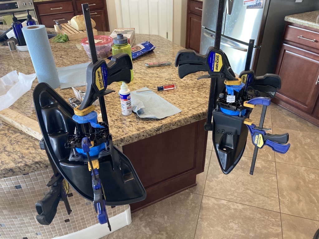
Baby, It's Cold Outside...
...and JB-Weld doesn't cure in the garage. So, we're moving into the kitchen. <Insert photo of delighted wife here>
Honestly, she's cool with it... to a point. If I start bringing body panels in, we're gonna have a "conversation". 
Spent a few hours with the headlight buckets, sealing them and epoxying the headlight mounts in place. Generally followed this thread (Thank you Blwalker105!):
https://thefactoryfiveforum.com/show...-and-Removable
The two buckets were clearly assembled by hand. The mounting flange for the headlights is glued into the bucket itself. Unfortunately, the flange on the left bucket was rotated differently from the right bucket, meaning the two headlights would not be rotated symmetrically to one another. [Ideally, we'd want them rotated so the low beam cutoff shutter was level. I settled for symmetrically rotated. -- maybe they're not level, but they'll both be canted inward the same amount. Hope that makes sense.] Consequently, the right bucket was far easier to deal with. It required zero modification, while the left bucket needed to have two of the holes that receive the headlight adjusters hogged out. Blwalker105 does a good job of describing this in his thread. On both buckets, I had to hog out the headlight holes a bit with a metal file. The glass portion of the lamps wouldn't insert easily/smoothly into the holes most likely due to misalignment between the bucket and the headlight mounting flange. I also had to dremel screwdriver slots into the screws since they didn't come that way from Hella.
Some pics...


Been experimenting with sourdough the past few weeks. My skills are improving!

-
Post Thanks / Like - 0 Thanks, 1 Likes
-
Senior Member
Brake line clips
Isaac made these clips for our build. 3D printed using PLA, 3 x 3/16" brake lines w/ 1/8" rivets.

I'm a little concerned that the thickness of the rivet tabs isn't sufficient, but figured we'd try it as is. If it breaks, it's easy to fix.
I'd be willing to print some more if anyone else would find them useful. Isaac's may also design/print a bracket for 2 lines shortly. It's hard finding time in his schedule during vacation! 
-
Post Thanks / Like - 0 Thanks, 1 Likes
-
Senior Member
Radiator drain
We've gotten pretty good at draining & refilling the coolant system ... because we've had to fix so many leaks. 
One of the royal pains was the radiator outlet. It was trapped inside the radiator frame. In order to open the drain we had to remove the radiator mounting brackets at the top, then shift the radiator up and forward.
So, we needed a solution. More JB-Weld and a few fittings along with a ball valve. We drilled a hole through the handle so we could safety-wire it in the closed position.


 Thanks:
  Likes:


 Reply With Quote
