-
01-08-2023, 01:46 PM
#121
Senior Member

Almost forgot to add these little stinkers:

-
01-11-2023, 08:48 AM
#122
Senior Member
-
01-13-2023, 09:05 PM
#123
Senior Member
-
01-13-2023, 09:10 PM
#124
Senior Member
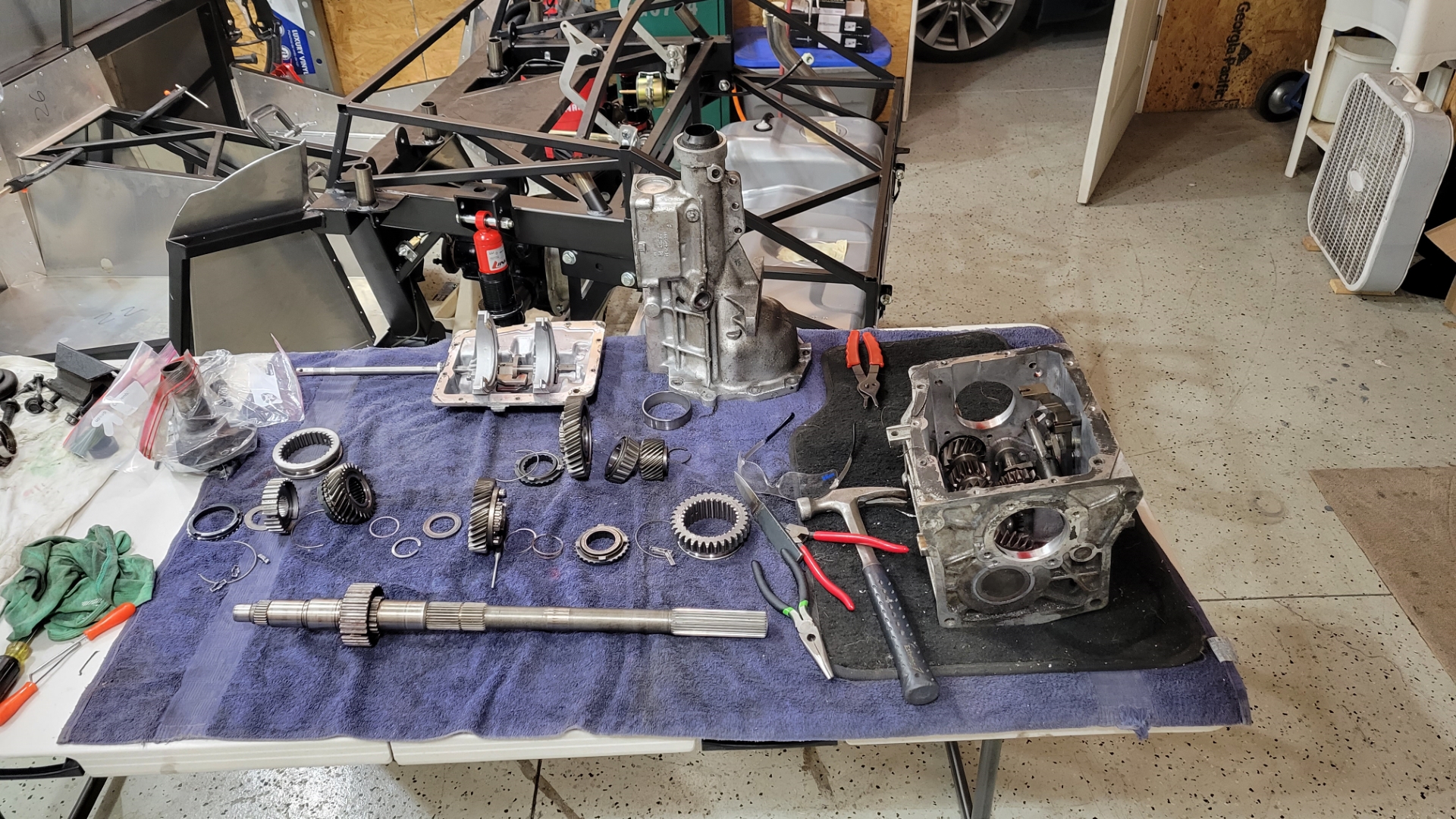
Now I need to take a little brake on the vehicle-specific progress for a few weeks. Not only am I waiting on some parts (including some POL items for the front brakes and the fuel tank), but I also have to paint my wheels, buy and mount some tires, and rebuild the T5 transmission. I was waffling on rebuilding the tranny but decided to pull the trigger after watching a few rebuild videos and seeing how much worn synchros and loose bearings can reek havoc on smooth shifts. Once the trans is done I can bolt it to the engine and toss those in the car.
I'll keep posting pics. They won't be car specific, but they will be related to the build.
-
01-14-2023, 11:03 AM
#125
You might want to check the hyd fluid reservoir height, to make sure the fluid level is higher than the master cylinder. It looks like you have plenty of room to work with.
20th Anniversary Mk IV, A50XS Coyote, TKO 600, Trunk Drop Box, Trunk Battery Box, Cubby Hole, Seat Heaters, Radiator hanger and shroud.
-
Post Thanks / Like - 1 Thanks, 0 Likes
 MB750
MB750 thanked for this post
-
01-15-2023, 08:14 AM
#126
Senior Member

Originally Posted by
Railroad

You might want to check the hyd fluid reservoir height, to make sure the fluid level is higher than the master cylinder. It looks like you have plenty of room to work with.
Yea, I thought of this during the install, but the manual says it's ok to be installed there so I went with it. When I think about it, once the system is bled it's air tight between the MC and the reservoir. Temp changes in the fluid cause it to expand and contract, which is the purpose of the reservoir during normal use. As long as there's some air space in the reservoir it should operate normally and shouldn't create a siphon effect since it's sealed. As the level drops (for whatever reason) that little rubber seal under the lid just expands down to take up the space.
Typically when I bleed brakes, especially when new, I use my air compressor on a very low setting and force the fluid from the reservoir thru the MC's and down to the calipers. Once fluid is coming out of all the bleeders, then I pump the brakes and bleed the air out like normally. Just have to make sure the caliper bleeders are open when you do this, and once fluid starts coming out you close them quickly. I've done this on countless Harleys and it works great. I've got a little plate with a rubber pad on one side and a hole in the middle. I put my rubber tipped air nozzle into the hole and push down on the whole affair when I pressurize the reservoir. I'm only talking like 2 psi here, just enough to get the fluid flowing. Since this reservoir is the size of a shot glass I'll have to check the level frequently while I do this.
I also hit the calipers with a dose of pressurized air as well to get the pads up against the rotors. This frees up maximum volume in each caliper so there's minimal losses in reservoir during bleeding.
But back to your point, I still may move it to the firewall, or up on the 3/4" tube in front of the footbox. The last thing I want is my brakes going Tango Uniform....
Last edited by MB750; 01-15-2023 at 08:24 AM.
-
01-15-2023, 10:08 AM
#127
Not a waxer

I once had a landscape employee who thought liquid could run uphill. Try as I might she never got it.
Jeff
-
Post Thanks / Like - 0 Thanks, 1 Likes
-
01-15-2023, 11:18 AM
#128
Senior Member
Originally Posted by
Jeff Kleiner
I once had a landscape employee who thought liquid could run uphill. Try as I might she never got it.
Jeff
I find it obvious the key word in that comment is "had". 
-
01-15-2023, 11:24 AM
#129
Senior Member
FFR sells the brake reservoir for $67. It's the whole enchilada (mount, hoses, fittings, canister, etc...) so I'm gonna buy it and move both up on the frame rail like so many people have already done.
https://www.factoryfiveparts.com/341...ir-components/
And I'll have two, because I'll probably go with a hydraulic clutch eventually.
-
01-15-2023, 07:40 PM
#130
Senior Member
Thanks to Eric the Car Guy and this video to get me in the correct direction:
-
Post Thanks / Like - 0 Thanks, 1 Likes
-
01-16-2023, 10:58 AM
#131
I think you can attain a higher mount on the front of the fox box, where you are, than on the frame rail.
I put mine on the frame rail and the bottom of the reservoir is not higher than the master cylinder.
The top of the full fluid level is higher. So, my reservoirs need to stay full.
Just FYI, before you mock up the move.
20th Anniversary Mk IV, A50XS Coyote, TKO 600, Trunk Drop Box, Trunk Battery Box, Cubby Hole, Seat Heaters, Radiator hanger and shroud.
-
Post Thanks / Like - 1 Thanks, 0 Likes
MB750 thanked for this post
-
01-17-2023, 07:37 AM
#132
Senior Member
Originally Posted by
Railroad
I think you can attain a higher mount on the front of the fox box, where you are, than on the frame rail.
I put mine on the frame rail and the bottom of the reservoir is not higher than the master cylinder.
The top of the full fluid level is higher. So, my reservoirs need to stay full.
Just FYI, before you mock up the move.
I thought of that, but then the reservoir blocks that large hole. For the life of me I have no idea what that huge hole is for, but I just don't think I should block it.
I got another reservoir on order from FFR. Putting the two of them next to each other, as high as possible, is the goal.
Matt
My build thread
here
-
01-17-2023, 07:38 AM
#133
Senior Member
I created a dedicated thread for my Cadillac (Brembo) front calipers here

I'll paint them red eventually, and put a larger Brembo sticker on the outside surface so everyone knows how cool my brakes are. 
Matt
My build thread
here
-
Post Thanks / Like - 0 Thanks, 1 Likes
 BRRT
BRRT liked this post
-
01-17-2023, 08:06 AM
#134
Originally Posted by
MB750
I thought of that, but then the reservoir blocks that large hole. For the life of me I have no idea what that huge hole is for, but I just don't think I should block it.
I got another reservoir on order from FFR. Putting the two of them next to each other, as high as possible, is the goal.
Typically thats where the front end wire harness leg goes through that hole with a grommet and them runs up the 1x1" tube
MK4 Complete Kit #10315 / Coyote G3 / TKX / 427 HardTop
Build Thread Production Date: 2/26/22, Registered 5/19/22, Graduated 3/1/2023
-
Post Thanks / Like - 1 Thanks, 0 Likes
MB750 thanked for this post
-
01-19-2023, 01:21 PM
#135
Senior Member
Ok, better fuel lines:


And don't let anyone tell you that copper nickel is "easy to bend..." Like hell it is! This is 3/8" line and it was almost as hard to bend as the 5/16" steel that came from FFR. At least now I'll have the flow. I put hose barb fittings on each end so I can just use flex line rated for FI pressures.
Matt
My build thread
here
-
01-22-2023, 05:24 PM
#136
Senior Member
Diving into the transmission, I discovered these have an issue:

These are the synchronizer keys for the 1-2 gear shift. So I figured, they're steel, and I have a TIG welder, lemme straighten them out, drop a bead or two, and be good to go.
Well, no dice. They're some really hard and brittle steel, and my TIG doesn't drop the amperage low enough to run a really small bead. I even cranked up the pulse to soften the heat and it still kept wanting to melt. Well, I tried.
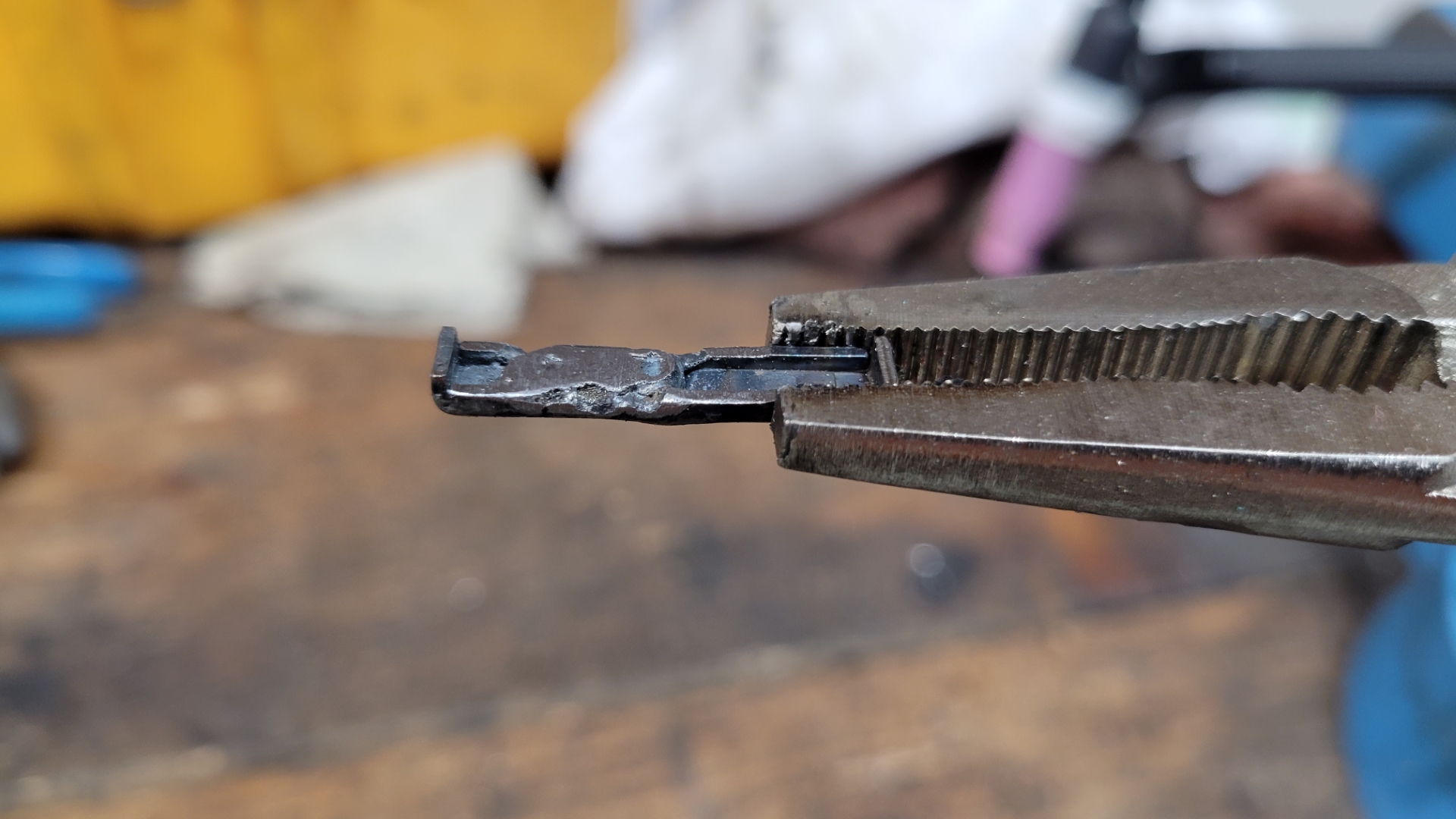
I was having trouble finding a set of just those keys, but after I discovered their actual part number I found a bunch of sources.
Matt
My build thread
here
-
01-22-2023, 06:27 PM
#137
Might be just camera angles, but some of those fuel lines look like they have some significant creases in them that could restrict flow. These are cheap and help maintain the integrity of the tube: https://a.co/d/9WYGGFm
MK4 Complete Kit #10315 / Coyote G3 / TKX / 427 HardTop
Build Thread Production Date: 2/26/22, Registered 5/19/22, Graduated 3/1/2023
-
01-22-2023, 10:21 PM
#138
Senior Member
Originally Posted by
JeffP
Might be just camera angles, but some of those fuel lines look like they have some significant creases in them that could restrict flow. These are cheap and help maintain the integrity of the tube:
https://a.co/d/9WYGGFm
Thank you, but that's exactly the same tool that caused the weirdness in the tubing. It would start kinking the line after about 45 degrees of bend. Combined with how hard that line was and it turned into a bit of a pain in the ***.
Makes me wonder if I couldn't have just ran regular copper.
Matt
My build thread
here
-
01-23-2023, 06:22 AM
#139
Not a waxer
Originally Posted by
JeffP
Might be just camera angles, but some of those fuel lines look like they have some significant creases in them that could restrict flow
Id be even more concerned by the flow restriction caused by those brass hard 90 degree fittings.
Jeff
-
01-23-2023, 08:39 AM
#140
Senior Member
In all honesty, I'm not happy with how it's turned out either. Why is this fuel line kicking my *** so much?
It's got me tempted to just run braided 3/8" PTFE from the tank to the regulator. Am I bound by running hard line down on the frame rails or can I go flex the whole way?
Matt
My build thread
here
-
01-23-2023, 09:06 AM
#141
Originally Posted by
MB750
In all honesty, I'm not happy with how it's turned out either. Why is this fuel line kicking my *** so much?
It's got me tempted to just run braided 3/8" PTFE from the tank to the regulator. Am I bound by running hard line down on the frame rails or can I go flex the whole way?
I haven't installed mine yet (hopefully this weekend), but I'm doing -6AN PTFE braided stainless for the whole system. 4 hoses that I am making to length myself. Haven't decided whether to go along the 4" tube or along the top of the tunnel.
<><><><><><><><><><>
Mk4 Roadster complete kit Chassis F5R1010480RD
Ordered Dec 2021, Delivered Sept 2022, First start Mar 2023
Completed October 2023
IRS, Wilwood, 17" wheels, Forte 427W/TKX/EdelbrockEFI
-
Post Thanks / Like - 1 Thanks, 0 Likes
MB750 thanked for this post
-
01-23-2023, 09:29 AM
#142
Senior Member

Originally Posted by
MB750
In all honesty, I'm not happy with how it's turned out either. Why is this fuel line kicking my *** so much?
It's got me tempted to just run braided 3/8" PTFE from the tank to the regulator. Am I bound by running hard line down on the frame rails or can I go flex the whole way?
I ran -6AN SS braided PTFE lines along the 4" tube for my fuel and return lines. FYI, the OD of the -6AN PTFE is slightly smaller than regular SS braided rubber lines. I think I found the appropriately sized clamps through Earl's.
-
Post Thanks / Like - 1 Thanks, 0 Likes
MB750 thanked for this post
-
01-23-2023, 12:38 PM
#143
Senior Member
That does it, it's coming out. 3rd time's the charm... 
Matt
My build thread
here
-
01-23-2023, 02:41 PM
#144
Senior Member

I haven't done it but, when I do, I think this is the way. Some people are really good with this stuff. I will also run ss braided PTFE lines the whole way. I think.
-
01-29-2023, 08:39 AM
#145
Senior Member
Just some notes for future short-term goals while I'm thinking about it. I've almost got the tranny back together so I'll consider it done for January. Things got a little "spendy" for January, I need to reel that business in for February. These goals are more focused on parts I have on hand, not so much things I need to buy (except for the wheel stuff and fuel lines):
February -
Engine, trans, and driveshaft installed
Wheels powder coated
Tires installed
Wiring harness laid out in chassis, terminations where applicable
New -6AN fuel lines
Install POL items in fuel tank (assuming I actually get these items...)
Finish and bleed brakes (again, POL items pending...)
Finish aluminum panels in back half of car
Matt
My build thread
here
-
Post Thanks / Like - 0 Thanks, 1 Likes
-
01-31-2023, 11:25 AM
#146
Senior Member
Matt
My build thread
here
-
01-31-2023, 11:57 AM
#147
Senior Member

Originally Posted by
MB750
In all honesty, I'm not happy with how it's turned out either. Why is this fuel line kicking my *** so much?
It's got me tempted to just run braided 3/8" PTFE from the tank to the regulator. Am I bound by running hard line down on the frame rails or can I go flex the whole way?
You can run full flex lines, no issues with doing it this way. Just make sure they are a name brand PTFE line (ie: Fragola). This will also allow you to use some nice -AN fittings for a clean look and no leaking.

-
Post Thanks / Like - 1 Thanks, 0 Likes
MB750 thanked for this post
-
01-31-2023, 02:56 PM
#148
Senior Member
Originally Posted by
Fman
You can run full flex lines, no issues with doing it this way. Just make sure they are a name brand PTFE line (ie: Fragola). This will also allow you to use some nice -AN fittings for a clean look and no leaking.
Yes, that is exactly the route I'm going with. PTFE all the way from the tank pickup to the carb.
Matt
My build thread
here
-
Post Thanks / Like - 0 Thanks, 1 Likes
Fman liked this post
-
02-05-2023, 08:31 AM
#149
Senior Member
Moving right along:


New throwout bearing (also called a clutch release bearing, apparently), and I buttoned it all back up. Kinda regret not going with a new clutch and flywheel, but I need to curb expenses a little. I'm discovering a LOT of items I'm having to source myself for one reason or another and it's adding up. If I were having a 500hp engine put in here I would have put those two higher on the list, but since this is basically just a warmed over 302, the OEM stuff should be ok. Worse case scenario, I'm dropping the trans a few months after it's roadworthy to install $300 worth of clutch bits. To me, that's a fun weekend.
My dad's gonna come up next weekend to help me install the engine/trans. Not much else tho. I'm expecting a POL shipment tomorrow, but I can only speculate what's in it. Hopefully fuel tank stuff.
Matt
My build thread
here
-
Post Thanks / Like - 0 Thanks, 1 Likes
-
02-05-2023, 09:04 AM
#150
Not a waxer
I see by the bellhousing that you're using a SN95 configuration which I assume you know moves the transmission farther rearward than in a Fox body. The last one that I built using SN95 components required the driveshaft to be shortened because the FFR T-5 shaft is set up for Fox length. Just a heads up for ya'.
Jeff
-
02-05-2023, 09:43 AM
#151
Senior Member
Originally Posted by
Jeff Kleiner
I see by the bellhousing that you're using a SN95 configuration which I assume you know moves the transmission farther rearward than in a Fox body. The last one that I built using SN95 components required the driveshaft to be shortened because the FFR T-5 shaft is set up for Fox length. Just a heads up for ya'.
Jeff
Jeff
No, I was not aware of that, thanks for bringing it to my attention. Just like the axle width, it's an other SN-95 curveball. I guess I kinda figured when I told FFR that my "donor" was a 95 they'd account for these types of things but I guess not.
How much shorter did you have to make your driveshaft?
Considering the overall length of my trans/bellhousing, I'm guessing if I were to make everything Fox Body equivalent I'd obviously need a bellhousing, but also the input shaft to the trans since that dictates the bellhousing "length" as well.
Also, follow-up question, but in your professional opinion do I have any more SN-95 specific ghosts in my closet that will jump out unforeseen?
Matt
My build thread
here
-
02-05-2023, 10:46 AM
#152
Not a waxer
Originally Posted by
MB750
Jeff
No, I was not aware of that, thanks for bringing it to my attention. Just like the axle width, it's an other SN-95 curveball. I guess I kinda figured when I told FFR that my "donor" was a 95 they'd account for these types of things but I guess not.
How much shorter did you have to make your driveshaft?
Considering the overall length of my trans/bellhousing, I'm guessing if I were to make everything Fox Body equivalent I'd obviously need a bellhousing, but also the input shaft to the trans since that dictates the bellhousing "length" as well.
Also, follow-up question, but in your professional opinion do I have any more SN-95 specific ghosts in my closet that will jump out unforeseen?
You are correct; if you change the bell it requires a different input. SN95 works but you will need to check the driveshaft (after setting the pinion angle) to see if it bottoms in the transmission during suspension compression. That occurred on the car I built with SN95 configuration and I had the shaft shortened...an inch as I recall. The shifter will move rearward so you'll need to open up the hole in the trans tunnel top.You already know that the rear end is 1.5" wider. The other oddity with SN95 is the engine's front dress. Don't know what your plan is there---if you go with aftermarket Fox based pulleys and brackets you'll have to also change the water pump. If you stick with SN95 and plan to use power steering you may find that the PS pump conflicts with the steering shaft.
Jeff
Last edited by Jeff Kleiner; 02-05-2023 at 10:58 AM.
-
Post Thanks / Like - 1 Thanks, 0 Likes
MB750 thanked for this post
-
02-05-2023, 12:22 PM
#153
Senior Member
Originally Posted by
Jeff Kleiner
You are correct; if you change the bell it requires a different input. SN95 works but you will need to check the driveshaft (after setting the pinion angle) to see if it bottoms in the transmission during suspension compression. That occurred on the car I built with SN95 configuration and I had the shaft shortened...an inch as I recall. The shifter will move rearward so you'll need to open up the hole in the trans tunnel top.You already know that the rear end is 1.5" wider. The other oddity with SN95 is the engine's front dress. Don't know what your plan is there---if you go with aftermarket Fox based pulleys and brackets you'll have to also change the water pump. If you stick with SN95 and plan to use power steering you may find that the PS pump conflicts with the steering shaft.
Jeff
Thanks Jeff, I appreciate your input.
My plan was to install the driveshaft during this whole process since I'll have help from my dad. Now what I may do is get the engine and trans installed, and then take off the rear shocks so I can easily articulate the driveshaft. In the upper most position get a measurement so I'll have an idea on driveshaft length and go from there.
Also regarding the front of the engine, mine's all dressed:

SN95 underdrive pulley, I bored out the inner hole on the Fox Body water pump pulley to make it fit, and the alternator mount is a very custom job so now they all line up. For some reason this engine had the Fox Body water pump and crank pulley (and all accessory brackets and mounting locations). Now it's nice and tight. No PS either, for now. If I do, it'll be electric.

Matt
My build thread
here
-
02-05-2023, 12:31 PM
#154
Not a waxer
Unless the photo is deceiving it looks like you have a smooth pulley on the water pump. Are you taking the belt from the crank pulley to the alternator with the back side of the belt kissing the pump and driving it or are you taking the belt up and over the pump to the alternator? If it’s the latter the pump will be spinning the wrong direction and the grooved belt won’t want to stay on the smooth pulley.
Jeff
-
02-05-2023, 04:43 PM
#155
Senior Member
The pump will be spinning opposite of the crank. I made 100% sure of that before ordering it and setting things up like this. The way I built my alternator adjusting bracket puts more tension on the pump pulley as I push the alternator up.
I've seen a few pics from other builds where they do the same orientation. Yes, there isn't much belt on the water pump pulley, but they don't have overheating issues.
Matt
My build thread
here
-
02-11-2023, 09:01 PM
#156
Senior Member
-
02-11-2023, 09:05 PM
#157
Senior Member

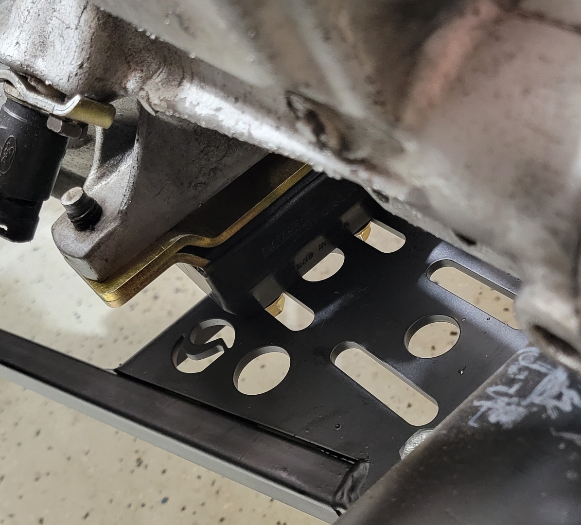
There was a plate that's used as an adapter between the transmission and the transmission mount. It's used to offset the trans mount rearward a bit and supposed to line up with the slots in the A-frame. Well, due to my SN-95 combination the mounting holes in the urethane were right in the middle of the two slots. So, removing that adapter bracket made all the difference. The mount by itself works swimmingly:
I also shoved the driveshaft all the way forward to see how it mounts up to the pinion flange:

No dice. Gotta take off about 3/4" to make it work.

Matt
My build thread
here
-
02-11-2023, 10:27 PM
#158
Senior Member

Originally Posted by
MB750
No dice. Gotta take off about 3/4" to make it work.
It's going to be more that 3/4". The slip joint at the trans will have some amount exposed. Not tight against the seal (be careful with that). You don't want it too long or you'll have difficulty getting it installed without taking stuff apart. Which shouldn't be necessary. Plus with your solid axle there will be some movement at the slip joint. Google how to measure for a driveshaft with a slip joint. There are plenty of how-to's. Or maybe the shop that shortens it will provide instructions to get the right length.
Build 1: Mk3 Roadster #5125. Sold 11/08/2014.
Build 2: Mk4 Roadster #7750. Sold 04/10/2017.
Build Thread
Build 3: Mk4 Roadster 20th Anniversary #8674. Sold 09/07/2020.
Build Thread and
Video.
Build 4: Gen 3 Type 65 Coupe #59. Gen 3 Coyote. Legal 03/04/2020.
Build Thread and
Video
Build 5: 35 Hot Rod Truck #138. LS3 and 4L65E auto. Rcvd 01/05/2021. Legal 04/20/2023.
Build Thread. Sold 11/9/2023.
-
Post Thanks / Like - 1 Thanks, 0 Likes
MB750 thanked for this post
-
02-12-2023, 07:09 AM
#159
Senior Member
Originally Posted by
edwardb
It's going to be more that 3/4". The slip joint at the trans will have some amount exposed. Not tight against the seal (be careful with that). You don't want it too long or you'll have difficulty getting it installed without taking stuff apart. Which shouldn't be necessary. Plus with your solid axle there will be some movement at the slip joint. Google how to measure for a driveshaft with a slip joint. There are plenty of how-to's. Or maybe the shop that shortens it will provide instructions to get the right length.
Good points. There's a drawing from FFR floating around that says my combo should have a driveshaft that's 10.375" (compared to the Fox Body driveshaft of 11"). See here:

It's grainy, but if you zoom in you can see the values. Per your suggestion what I'll do is remove the driveshaft and measure the distance from a consistent point on the pinion flange to the trans output shaft with the axle at full slack, then remove the shocks and jack the axle all the way up and measure again. This will tell me the "take-up" during suspension travel. When I know the absolute tightest that distance will be, then I'll back out the math to get my new driveshaft length, based on accepted clearances of course. According to Motortrend, 1" of slip yolk travel from the tightest position is the number.
Last edited by MB750; 02-12-2023 at 07:12 AM.
Matt
My build thread
here
-
02-12-2023, 08:10 AM
#160
Not a waxer
Originally Posted by
MB750
No dice. Gotta take off about 3/4" to make it work.
Sorry…told ya’….make it a full inch.
Jeff
-
Post Thanks / Like - 1 Thanks, 0 Likes
MB750 thanked for this post


 Thanks:
  Likes:


 Reply With Quote