I'm looking for some help installing the engine and transmission in my Mk IV Roadster.
I am using a Blue Print Engine 427 / 4R70W combination. While I have the right side engine mount bolted into place, I am having trouble with the left side. The engine mount is fastened loosely in the frame. The engine block attachments points for the engine mount are forward of the engine mount by about 1 inch. Looking at the transmission tail shaft, it looks like it needs to move to the right to align with the IRS. Moving the tail shaft right would also help align the engine mount with the engine block. Unfortunately the transmission tail shaft will not go further to the right. It hits the e-brake hardware in the transmission tunnel.
Has anyone else run into this problem or have an idea what I am doing wrong?
If it matters, my BPE package came with a GearStar 4R70W instead of one from Performance Automatic.
I went through a very similar thing as you days ago. 4 times actually as I needed to lift the engine back up a few times. It's definitely a drag. For the most part, I did what you are doing. The alignment pegs, once in, will both bee at the very top of the hole. What worked for me was to do as you did, align the passenger side first, move the transmission rear end as much toward the passenger side as possible, but this could be different depending on where the DS tab is in relation to the hole. If it's toward the front of the car, push the rear of the transmission toward the passenger side, and vice versa. After doing that I adjusted the balancer on my engine hoist so it pulls more on the passenger side, released the pressure so the engine sits down a bit, and then used a pry bar on the passenger side to lift that side up by 1/2 to an inch (or as much as you can without popping that side out), after a few tries the DS side popped into place. What would help is while you're doing that, you had another person on the DS side pushing the engine sideways toward you.
I thought I would do a bit of an update. As mladen said, some prying coupled with elongating the slots on the engine mounts got things to align. What I couldn't resolve was getting the engine to sit level left to right. The left side needs to go down but can't because a tab on the transmission case is hitting the 1" square tube that runs from the 4" round tube to the top of the transmission tunnel. This is on the driver's side. While I could probably move the engine to the right enough to gain the needed clearance, if the engine rocks at all when running, the transmission will be hitting causing rattles. I'm going to need to pull the engine / transmission to cut this tab off. While the right side has clearance, I am going to cut that tab off also while I have the transmission out.
I have enclosed some pictures to show what I mean. I'll get some better pictures and post them once I pull the engine / tranny out.
mladen... I'm curious about your install. Does your roadster have clearance in this area, left and rights sides? If so, how much clearance do you have?
I pulled the engine / transmission today to fix the interference problem I wrote about in my earlier post. I have include pictures to more clearly show where the interference is with the chassis along with a better picture of the tab on the transmission. The second picture shows a before and after view of the engine / transmission installed in the car. You can see that once the tab is removed, there is clearance between the transmission and the chassis. Taking care of this fixed my installation problem.
I have some follow up questions that I am hoping someone can help me with.
As a reminder I am installing a 4R70W into a Mark IV Roadster. The transmission is part of a BluePrint engine 427 / 4R70W package.
I have the engine / transmission installed with the engine mounts loosely bolted into place on both the engine and the chassis. As I move under the car to install the FFR transmission A-frame and mount, I am running into the following two problems:
For the A-frame to clear the transmission oil pan, the transmission tail housing must go up a lot (as compared to when it is resting on top of the chassis cross member). The center line of the transmission output shaft will be 1 to 1 ½ inches above the center line of the IRS drive shaft mount to gain the needed A-frame / transmission oil pan clearance. At this height, the transmission mount will also be 1 ½ inches above the A-frame driving the need for spacers.
Raising the transmission enough to directly align the transmission output shaft with the the IRS driveshaft mount causes the transmission to hit the emergency brake brackets welded to the chassis. (Note that the transmission needs to go higher still to allow the A-frame to clear the transmission oil pan.) The emergency brake handle brackets also interfere with the solenoid plug on the right side of the transmission. Note that I removed the e-brake handle to get the engine / transmission installed. Even without
raising the transmission, the FFR supplied e-brake is not going to work in this position. The e-brake cable clevis hits the oil pan rail.
Questions:
Given the above problems, do I have something installed wrong? Has anyone else run into these problems with their 4R70W install?
Is there a different A-frame available that will clear the transmission oil pan without lifting the transmission as much?
What is the maximum, acceptable driveshaft down angle with the IRS? I'm thinking maybe the transmission is meant to be mounted high enough for the A-frame to clear the transmission oil pan.
Is interference expected between the 4R70W and the emergency brake? Assuming the answer is yes, does anyone know of a different e-brake solution using the FFR supplied parts? I am aware of the e-Stopp solution and what Lokar sells. I would like to make what I have work if possible.
Make sure you have the correct input yoke that goes into the 4R70W transmission. I had to get the correct one. FFR and Blueprint did not supply me with the correct one. See post#36. For wiring on the 4R70W see post#22. Maybe they have corrected this for you vs me.
You're right about the slip yoke. The one supplied by FFR fits a TKO and an AOD. The outside diameter is too small and will cause a leak at the transmission tail shaft seal if used with a 4R70W. The 4R70W requires a unique slip yoke. The Sonnax T2-3-14061HP is one example that will work with the 4R70W and the FFR supplied driveshaft / 1330 series u-joints. Whether you get the slip yoke from Sonnax or Dana - Spicer 2-3-14061X (much cheaper), the barrel will be longer than the AOD slip yoke making the install impossible once the engine / transmission is in place.
The wiring issue you had has been fixed. My engine / tranny package from BluePrint uses a GearStar tranny. They include a Quick 4 controller made by US Shift. The controller comes with a complete installation manual and wiring diagram. My wiring issue is on the other side of the transmission (the passenger's side). It's a 10 pin connector with 7 wires used. It controls the shift 1 / shift 2 solenoids, torque converter lock up, etc.
Did you run into any of the problems I am having?
No, my install was in a 33 Hot Rod . No frame issues. Trans was from performance transmission and used a MSD trans controller. The wiring I showed was for back up lights and Neutral safety switch for that build
I'm not familiar with what FFR is currently offering, my kit is about five years old, but I put a 5.3 LS with a 4L60E trans in my MKIV. I Moved the parking brake to the top of the trans tunnel using an after market handle. I fabbed new motor and trans mounts and moved the lower portion of the trans tunnel about an inch to the passenger side. Hopefully, there's a better solution now, but the pan on the 4L60 is really wide. I changed motor mounts because of using exhaust manifolds rather than headers but I was unable to find a way to use the trans mount that came with the kit.
I copied what evvander11 did on the other forum, to install our AOD transmissions. Should be very similar, I'd think. The wide stance on the driver side is for shifter clearance.
Kyle... I like your plywood template. That is a good idea on how to fixture it for welding.
I think I am going to do a variation. I am going to cut the 3/4 inch square tubes off of the FFR mount then re-weld them onto a new piece of plate steel that is 1 to 2 inches wider that the FFR plate. That will change the angle of the square tubes while moving them out away from the tranny oil pan. While I will loose the laser cut FFR logo, it will take less welding.
I did ask FFR what drive line angle they designed to. They told me they try to achieve 0 to -1 degree. I'll be checking that as well once I get the new A-frame fabricated.
Kyle, your post is helpful as we are mounting the same in our MK4. It looks like you took the mount straight to the transmission without the bracket or the spacers? Did that give the the right angle for the AOD? THanks.
Originally Posted by kgkeys
I copied what evvander11 did on the other forum, to install our AOD transmissions. Should be very similar, I'd think. The wide stance on the driver side is for shifter clearance.
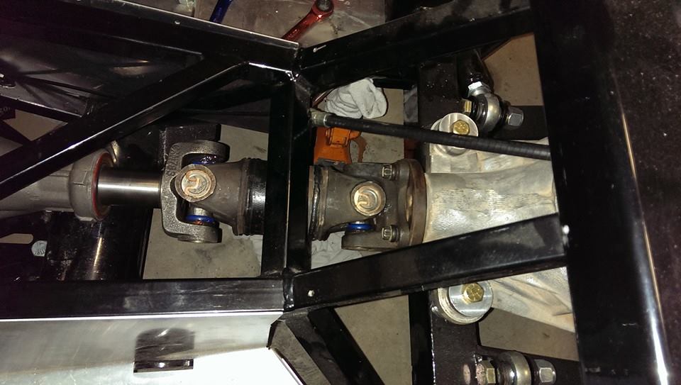
Mine is the old thunderbird-style IRS, but yeah it ended up basically a straight-shot. I believe there's just enough right-to-left offset between the trans and the diff, to exercise the u-joints, but otherwise it's basically straight.
I would think the yoke should be in the transmission further. But I'm not an expert either.
It's totally fine. In the picture below, the faint red line is where you see the seal riding. The sharp red line is how far the splines of the output shaft extend beyond the seal. Fully 2/3 of yoke is splined to the output shaft.
Kyle, your post is helpful as we are mounting the same in our MK4. It looks like you took the mount straight to the transmission without the bracket or the spacers? Did that give the the right angle for the AOD? THanks.
Kyle... While I made a different modification to the FFR tranny mount, the concept is the same. I installed my mount below the chassis brackets / tabs and used a single washer between the mount and the tranny. FFR designed the drive line angle with the IRS to be 0 to -1 degrees. With the way I mounted it, I got a measured -0.5 degrees.
Kyle... While I made a different modification to the FFR tranny mount, the concept is the same. I installed my mount below the chassis brackets / tabs and used a single washer between the mount and the tranny. FFR designed the drive line angle with the IRS to be 0 to -1 degrees. With the way I mounted it, I got a measured -0.5 degrees.
Jim
I'd like to see what you came up with, if you can provide pics. I have intentions to upgrade from the AOD to a 4R70W, some day. I'm sure your work could be helpful to others, as well.
The only picture I took is attached. A few comments on the picture:
1) I cut the 3/4 inch square tubing off of the FFR transmission mount and re-used them
2) I replaced the center section of the FFR mount (the one with the laser cut FFR logo) with my own piece of 1/4 inch steel. I made this piece wider than the FFR mount so the 3/4 inch tubing would clear the 4R70W pan. I welded the 3/4 inch square tube to the new steel plate.
3) If you do this, make sure the left side 3/4 inch square tube clears the transmission shift arm when the sift arm in the the "L" position - one click past drive. I didn't check and got lucky that it cleared.
4) The picture I posted shows my new tranny mount positioned above the FFR chassis mount "tabs" as the assembly manual suggests. When I did this, I found my drive line angle was +0.5 degrees - out of spec by a 1/2 degree. I moved it to below the chassis tabs and added one washer. This resulted in a -0.5 degree drive line angle which is within the FFR spec of 0 to -1 degrees. Cobra Transmission Mount.jpg
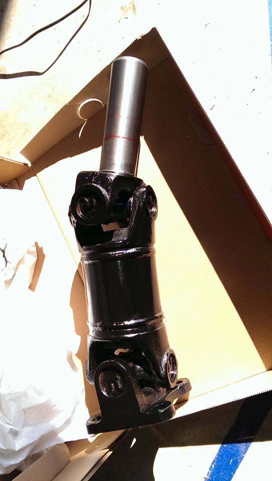
Another thing to note: When you switch from the AOD to the 4R70W, the AOD slip yoke will fit into the 4R70W tail shaft / splines. Unfortunately, the AOD slip yoke outside diameter is too small to allow the 4R70W tail shaft seal and stop the transmission fluid from leaking out. The 4R70W requires a unique slip yoke. The Sonnax T2-3-14061HP is one example that will work with the 4R70W and the FFR supplied driveshaft / 1330 series u-joints. Whether you get the slip yoke from Sonnax or a Dana - Spicer 2-3-14061X (much cheaper), the barrel will be longer than the AOD slip yoke making the install impossible once the engine / transmission is in place with an IRS. To fix this, I cut the 4R70W slip yoke so it was 1 /4 inch shorter than the AOD slip yoke. See the 2nd picture. The short piece in the picture is the amount I cut off. There is still has plenty of spline engagement and with the IRS, it won't move in and out. Cobra 4R70W Slip Yoke.jpg
Jim S,
I sent you a PM with my phone number.
I am planning on installing a 4R70W also and I'm hoping I could talk with you directly about your install.
Please give me a call when you can.
Thanks,
Nathan
FFR6682 - received 7/30/08 - MK 3.1 complete kit, Forte built Ford Racing BOSS 427W(475HP/500lbs), TKO600, Power steering, Power Brakes, Hydraulic Clutch, VPM Front/Rear sway bars, Bump steer kit, SAI mod, 13"Front/11.65"Rear Mustang Cobra rotors w/calipers, NITTO NT05s - 255/40R17-Front, 315/35R17-rear,3.55 IRS.
Visit my Blog: http://crawleyscobra.wordpress.com
I didn't get your PM. I suspect my spam filter put your email in the junk folder and I deleted it. I sent you a PM with my cell phone number. Reach out. I'm happy to talk.
I didn't get your PM. I suspect my spam filter put your email in the junk folder and I deleted it. I sent you a PM with my cell phone number. Reach out. I'm happy to talk.
Jim S.
Jim,
I looked at my Forum messages and did not see a message from you either. Technolgy, you got to love. :-).
FFR6682 - received 7/30/08 - MK 3.1 complete kit, Forte built Ford Racing BOSS 427W(475HP/500lbs), TKO600, Power steering, Power Brakes, Hydraulic Clutch, VPM Front/Rear sway bars, Bump steer kit, SAI mod, 13"Front/11.65"Rear Mustang Cobra rotors w/calipers, NITTO NT05s - 255/40R17-Front, 315/35R17-rear,3.55 IRS.
Visit my Blog: http://crawleyscobra.wordpress.com


 Thanks:
  Likes:


 Reply With Quote