-
Senior Member

E connection question
I am finishing up wiring the controls for a new lift and looks like the console button has a couple wires loose from the switch.
The common wire is still connected. The two posts open are “normally open” and “normally closed.
I replaced the ring terminals and about to re-attach.
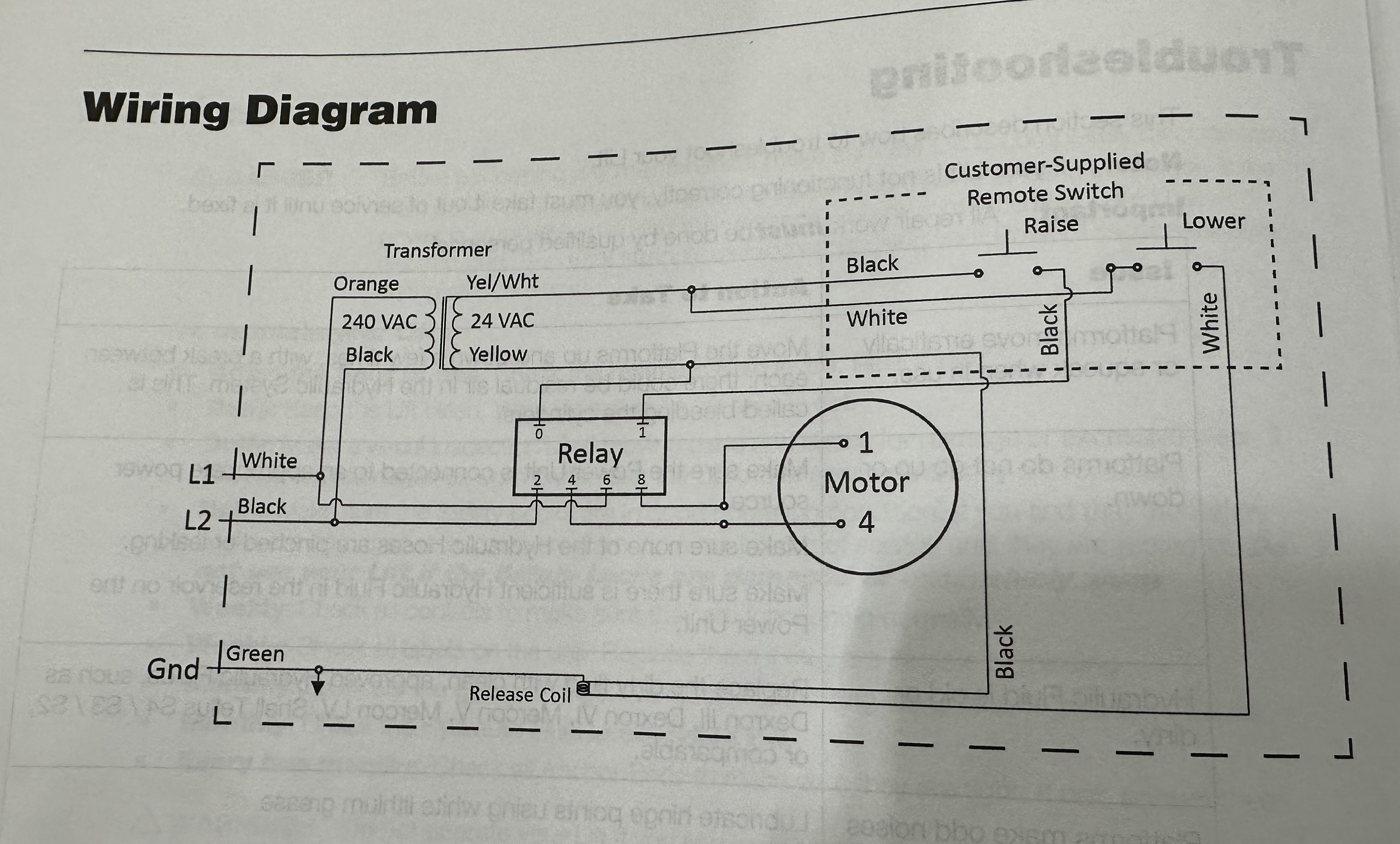
From the wiring diagram am I correct that the yellow/white wire should go to the “normally closed” position?
This is one of those areas sometimes I know just enough to be dangerous.

-
The switch and wires shown in your photo don't match the what's shown in the "remote switch" part of your schematic. The schematic actually shows 2 switches. In essence they are set up to form a single pole double throw circuit.
Are we to presume that the switch in your picture is one of those two switches and that you have a second, duplicate one?
In the schematic each switch only gets two wires connected to it. Black goes to the common connection on both switches and then the two other wires go to the normally open connection on each switch. The reason we know that the normally open connection is used is because the circuit/switch is depicted in the schematic as being "open" (not completing the connection between the common and other contact). If you think about it this make sense. You only want the lift to be running when you press the switches, not the other way around (off when you press the switches).
BTW The reason they have used two switches instead of a single SPDT toggle switch is to deliberately and physically separate the up and down control of the lift for safety reasons.
You need to trace out the wires to confirm but I suspect the yellow/white stripe wire goes to the one switch and the green/yellow stripe wire goes to the other switch.
I hope my explanation makes sense and doesn't come off as being condescending in any way...I just wanted to make sure I covered everything....as your personal safety is involved.
Earl
Last edited by narly1; 03-20-2023 at 06:21 AM.
1st Speedstar in Canada 31 March 2023.
Built by me 302 engine, AOD trans, 3.55 IRS.
-
Did that switch come with the lift?
Do you have a link for this lift with more info?
What is that “release coil” used for? Does some mechanical part of the lift actuate the switch?
'33 Hotrod, #1047 Gen 1, delivered on 2/27/18, go cart on 9/24/18.
LS3 w/Gearstar Level 3 4L65e Tranny, Yank converter, Lokar shifter, Electric PS, Vintage AC/Heat/Def, 8.8" 3.55
TorqThrust II Wheels w/Toyo Proxy T1 Sport Tires, F 235/45ZR17 R 295/35ZR18
Garage Built, Driveway Painted.
-
Senior Member
Thanks for the help gents. I appreciate the help and would never take any comments as condescending, again thanks.
Yes everything pictured came with the lift. Certainly not something I would alter.
The image below is exactly what I have with the lift. It is a bendpak mds6 ext-F. The two wires in question are the yellow and the Yellow with green stripe. The more I look the more I don’t understand the wiring diagram with what I was given. I have a ticket in with bendpak support, haven’t heard back yet but would anticipate an answer in the next day or two.
The assembly instruction book isn’t too helpful as it just states that the console arrives pre-assembled with the buttons/switches already wired. The install crew , who have now been released from their work, appear to have torn the connections from the buttons as the ring terminal was still attached without the wire. thus the current confusion. Again thanks for any thoughts. Before operation I will certainly be awaiting bendpaks verification it’s wired correct at this point.

-
Looks like the yellow/white wire should get connected to the normally open on both switches.
The schematic looks like it’s possibly an old one as they show the yel/wht wire connecting to a black and a white wire that goes to each switches N.O. connection.
Electrically it’s the same, just confusing as to why the wire colors are not the same as shown in the schematic, and why it says Customer Supplied switches. I don’t see a red wire in the schematic either.
Both of those switches must be momentary push button switches that you need to keep pressed to operate the up and down function.
'33 Hotrod, #1047 Gen 1, delivered on 2/27/18, go cart on 9/24/18.
LS3 w/Gearstar Level 3 4L65e Tranny, Yank converter, Lokar shifter, Electric PS, Vintage AC/Heat/Def, 8.8" 3.55
TorqThrust II Wheels w/Toyo Proxy T1 Sport Tires, F 235/45ZR17 R 295/35ZR18
Garage Built, Driveway Painted.
-
Senior Member
A couple back and forth questions this is the best BendPak can do so far. I don’t even have a white wire in my system as indicated. Ha! I still can’t sort this out. I’ll see if my electrician has some input but I am officially lost. Probably a simple connection but I’m surprised it’s been so difficult to get an answer from BendPak and that the wiring diagrams seem to be different. Maybe it makes sense to someone else.

-
Yes, that makes sense, it’s drawn better so you can see the relay contacts and what it’s going to do what when you push the up and down buttons.
As for the colors not matching you’ll either need to ohm the wires to figure out which color gets connected to what or post more pics of the rest of the electrical part showing us everything so we can help you out.
Do you have an ohm meter?
Last edited by JimLev; 03-24-2023 at 07:51 AM.
'33 Hotrod, #1047 Gen 1, delivered on 2/27/18, go cart on 9/24/18.
LS3 w/Gearstar Level 3 4L65e Tranny, Yank converter, Lokar shifter, Electric PS, Vintage AC/Heat/Def, 8.8" 3.55
TorqThrust II Wheels w/Toyo Proxy T1 Sport Tires, F 235/45ZR17 R 295/35ZR18
Garage Built, Driveway Painted.
-
Senior Member
Just following up , I ended up getting this sorted, BendPak came through with a clearer diagram and one of the wires simply isn’t used. Lift in , tested, no leaks, Floor going in and nesting for coupe delivery in the Fall.

-
Post Thanks / Like - 0 Thanks, 1 Likes
-
Curmudgeon


Originally Posted by
MSumners

As an FYI: The ring terminal without heat shrink in this photo is not crimped correctly. The crimp closest to the screw is for the bare conductor and the one further away is a strain relief. It should crimp the conductor and insulation. That's why it's bigger.
MKII "Little Boy". 432CI all aluminum Windsor. .699 solid roller, DA Koni shocks, aluminum IRS, Straight cut dog ring T-5, 13" four piston Brembos, Bogart wheels. BOOM!
-
Post Thanks / Like - 0 Thanks, 2 Likes
-
Originally Posted by
mikeinatlanta
As an FYI: The ring terminal without heat shrink in this photo is not crimped correctly. The crimp closest to the screw is for the bare conductor and the one further away is a strain relief. It should crimp the conductor and insulation. That's why it's bigger.
Yep. I would remove that connector and put a new one in and add some heat shrink to it.
My Type 65 Coupe: Ordered May 27, 2021. Arrived November 19, 2021.
I would like to treat my gas pedal as a binary operator. It would be nice to get the cooperation of everyone in front of me. 
-
Senior Member
Originally Posted by
mikeinatlanta
As an FYI: The ring terminal without heat shrink in this photo is not crimped correctly. The crimp closest to the screw is for the bare conductor and the one further away is a strain relief. It should crimp the conductor and insulation. That's why it's bigger.
Good call! Oddly enough that’s how it arrived from the factory. The other two I added. I’ll snip it and heat shrink it. Thanks for the advice.


 Thanks:
  Likes:


 Reply With Quote