Midwest Classic Insurance

Visit our community sponsor

Thanks Thanks:  0
Likes Likes:  5
Page 13 of 51 FirstFirst ... 3111213141523 ... LastLast
Results 481 to 520 of 2016

Thread: More progress made on the body : )

  1. #481
    Senior Member sk7500's Avatar
    Join Date
    Feb 2011
    Posts
    377
    Post Thanks / Like
    We need a name for that disease and is there a cure?

  2. #482
    Banned
    Join Date
    Aug 2011
    Posts
    669
    Post Thanks / Like
    it's called "empty wallet-wife left me(i didn't notice i was in the garage)-what day is it?" disease. no, there is no cure!

  3. #483
    Senior Member The Stig's Avatar
    Join Date
    Feb 2011
    Location
    Charlotte, NC
    Posts
    2,004
    Post Thanks / Like
    It has been quite some time since I've posted new progress with my car. I just started a new project in Solon, OH that has kept me slammed for the past few weeks; and probably will for at least another couple of weeks. But I am planning to get out and do a little more to finish the "interior", and try to get the bottom side buttoned up. (Skid Rails and aluminum panels). How have you guys fastened the bottom side aluminum panels: rivets or screws. I've thought of going ahead and tapping the holes for some 8 or 10/32 button head allen bolts. For accessability. But it's also pretty easy to just drill out the rivets and replace them if/when needed. What are your thoughts?

    I would also like to go ahead and place the nose aluminm in place, if I have the time. Not sure if I'll make it there this weekend though.

    I need to go through the dash wiring bundle, and try to figure out which wires are in place for the gauges, and what still needs to be run... The gauges will obviously need to be connected and working before I can plan to send it off to the interior guys...

    I'll probably have the registration and tag work completed while it's at Chuck Hanna's place, which means that it'll be finished and "ready" for the street when the interior work is done.

    Chuck estimated about 4 to 6 weeks to do the interior. For those of you who have used pro interior shops in the past, does this seem like a reasonable amount of time? too long? too short?

    I'm coming out of the 4th turn, up against the wall, and I can see the finish line.

    More updates & Pictures to follow.
    The Stig

    Some say, that I only know two facts about ducks, (both being wrong); and that if I could be bothered, I could solve the "da Vinci Code" in 47 seconds...
    All I know is that I'm called "The Stig".
    GTM #0081

  4. #484
    Banned
    Join Date
    Aug 2011
    Posts
    669
    Post Thanks / Like
    alot depends on the fabrication (like panels to upholster like kempo's car or fixes to door panels, etc.) and the shops existing workload. what kind of materials, modifications are you talking? just a basic recovering of what's there? how much did they quote? i'd rather wait & pay more for a quality job in the end, especially the materials and the stitching.
    Last edited by carbon fiber; 10-18-2012 at 09:58 AM.

  5. #485
    Senior Member The Stig's Avatar
    Join Date
    Feb 2011
    Location
    Charlotte, NC
    Posts
    2,004
    Post Thanks / Like
    It'll be a complete custom interior.

    The Materials will be Leather, Alcantara (Suede), Aluminum, Billet Aluminum handles.

    The colors will be Light/Medium Gray Leather, with a shade or so darker Alcantara. Aluminum accent trim work where it makes sense. I think that these colors will work well with the body color, and polished billet wheels.

    - Custom dash which will integrate a reworked porsche 997 turbo gauge cluster. (Alcantara will at least cover the Gauge pod. I'm thinking of having the rest of the dash, and the dash underside close out panels, covered in leather. But I'm not sure yet.) The dash will curve around and blend into the door panels, but the curve will flow downward creating an arm rest on each side. At least that's the thought process so far.

    - Center console (Leather and Aluminum)

    - Door panels that wrap. (Leather, Alcantara, and Aluminum, with brushed billet door handles)

    - Headliner (Alcantara, )

    - Firewall (Alcantara)

    - Engine cover (Leather).

    - I picked up a nice Black Leather Momo Steering wheel a few months ago. I may have it re-covered in leather that is the same color as the alcantara accents. But if it looks good as is, i'll probably leave it alone.

    - The leather will have contrast stitching that matches the darker gray accents.

    The only parts that may be re-used are the seats. But we're not 100% sure yet. I've been playing around with buying a set of Tillet B5's, but they're pricey. It may make better sense to put that money into the rest of the interior and keep the Gen-2 seats. I'm planning to take the dash, door panels, roll-bar covers, etc., and we'll figure out if they can (or should be) used in the design. From what I've told him that I want, I'm not sure that they can be.

    Cost is high... At least I think it is.

    But one thing is 100% certain. There will be a complete plan, and cost sheet agreed to, and I'll know exactly what I am going to get for my money BEFORE he starts to do anything at all. And he'll know exactly what I expect from him for the amount that we agreed on.

    I can't wait to get it to the point that he can start working on it. That's what the next couple of weekends will be for.
    Last edited by The Stig; 10-19-2012 at 10:12 AM.
    The Stig

    Some say, that I only know two facts about ducks, (both being wrong); and that if I could be bothered, I could solve the "da Vinci Code" in 47 seconds...
    All I know is that I'm called "The Stig".
    GTM #0081

  6. #486
    Senior Member flotowngtm's Avatar
    Join Date
    Apr 2011
    Posts
    145
    Post Thanks / Like
    Make sure that your arm does not rest on that aluminum, its gets super hot.
    I too have been looking at the B5's. I have been talking to the guys at piper motorsports. I need a seat for a 5-6 point harness and a HANS.
    There not as expensive as you might think if you factor in going with a different seat anyway. At least with the Tillett seats you wont be paying to get them reupholstered to match your interior.
    That MOMO wouldnt be the Trek-R would it? I think its the best one.

  7. #487
    Banned
    Join Date
    Aug 2011
    Posts
    669
    Post Thanks / Like
    sounds nice, and they'll probably need most of the time they quoted. the color scheme and the 997 guages sound cool also. i bought the momo "nero", it has black leather and suede, makes the ffr steering wheel look cheap by comparison. the tillets or any fixed position seat seems to not fit the car very well. you have to angle them back to get head clearance and then the front is angled upward. i haven't sat in a set, just seen pics and learned from the test fitting of the sparcos i'm modifying. (removing the corner in the bottom) the sparcos are only 14 inches wide in the back and i barely fit. 5'8" 180lbs. just make sure and get some measurements and double check. sounds like your on the home stretch, looking forward to seeing it finished!

  8. #488
    Senior Member flotowngtm's Avatar
    Join Date
    Apr 2011
    Posts
    145
    Post Thanks / Like
    Here is the measurements on the Tillett B5. You could take the same measurements off your stock GTM seat thats also a fixed position seat. Then you should be able to tell if they will fit or not.
    Attached Images Attached Images

  9. #489
    Banned
    Join Date
    Aug 2011
    Posts
    669
    Post Thanks / Like
    my main concern was the distance between my head and the rollcage.(specifically the left overhead bar) they'll fit in the car for sure, it's been done. even with the stock seats, my head was too close for me, to the rollcage. it's one of the problems with the car, especially with taller people. i'd imagine if you're 6' or taller you're looking at part of the cage looking forward out the front. the way i've got the sparco modified and with harnesses, strapped down i can't get my head closer than 3" to the rollcage. if your head is able to make contact with the cage at any position while strapped in, that's a problem. it would be even more of an issue with seatbelts where side to side movement isn't controlled like with harnesses. with the sparco seat width at 14" in the back, (a couple inches deep also) if i were any bigger of a person i wouldn't fit. the tillets do look like they are shallow in the back and wider than others. mike, have you sat in the car with the stock seats? how close is your head on the left side to the cage? i wasn't comfortable with the way it was.

  10. #490
    Senior Member flotowngtm's Avatar
    Join Date
    Apr 2011
    Posts
    145
    Post Thanks / Like
    That's one of the reasons I will be going with the HANS.
    The B5 is made to be mounted really low in the chassis. Much lower than another seat. Sure that would help with your height issue.

  11. #491
    Banned
    Join Date
    Aug 2011
    Posts
    669
    Post Thanks / Like
    flowtowngtm, have you sat in the ffr seats? how close was the cage to your head/ how tall are you? just curious, i know it's gotta be worse for taller guys. there's no way i'd feel comfortable with my head that close to the cage.

  12. #492
    Senior Member flotowngtm's Avatar
    Join Date
    Apr 2011
    Posts
    145
    Post Thanks / Like
    I have never sat in the seat installed in the car so I have no idea. But I should be good at 5'9"

    Stig, I dont know when I will be ordering mine or if I will as I am adding a second redundant rear hoop in the car and have to make sure that my head will clear it as my main concern. But from talking to a distributor it could take as long as 2 months to get a set in. Depending on when they have a large shipment coming to the states. Just to give you some heads up on time line.

    carbon fiber, I am sure these seats will go nicely with whatever your cooking up!

  13. #493
    Senior Member The Stig's Avatar
    Join Date
    Feb 2011
    Location
    Charlotte, NC
    Posts
    2,004
    Post Thanks / Like
    I'm hoping to spend some time tomorrow to get myself back into this build, and get it wrapped up. I don't really lack motivation, as much as simply finding time to dedicate more than an hour here and there.

    I can't get a lot done in short bursts. It takes more time than that for me. Pictures to follow!
    Last edited by The Stig; 03-19-2013 at 10:08 AM.
    The Stig

    Some say, that I only know two facts about ducks, (both being wrong); and that if I could be bothered, I could solve the "da Vinci Code" in 47 seconds...
    All I know is that I'm called "The Stig".
    GTM #0081

  14. #494
    Administrator David's Avatar
    Join Date
    Feb 2011
    Location
    Eldo CA
    Posts
    443
    Post Thanks / Like
    Do it Mike, do it!! I'll be working in the shop the weekend as well.

    David
    Mk4 Build Thread: http://thefactoryfiveforum.com/showthread.php?141-David-s-Mk4-Build-Thread

    GTM Project Build site: http://www.gtmbuild.com

    Few Cool GTM Parts: http://www.gtmbuild.com/parts.htm

  15. #495
    Senior Member The Stig's Avatar
    Join Date
    Feb 2011
    Location
    Charlotte, NC
    Posts
    2,004
    Post Thanks / Like
    Well I had a nice surprise today...

    I went out to work on the GTM. I wanted to crank it up and let it idle for a few minutes, and charge the battery a little, before I put it back up on jack stands to work underneath.

    I hit the fuel pump, pressed the start button, and it fired right up. I noticed almost immediately that the water temp was going up pretty quick. In 3 or 4 minutes, it went through 180 degrees, and straight to 220. The overflow tank was blowing coolant onto the garage floor. I heard a noise that sounded pretty strange as I was shutting it down. I thought that maybe the belt had jumped or that crank pulley bolt had backed out. It was a loud mechanical sounding noise.

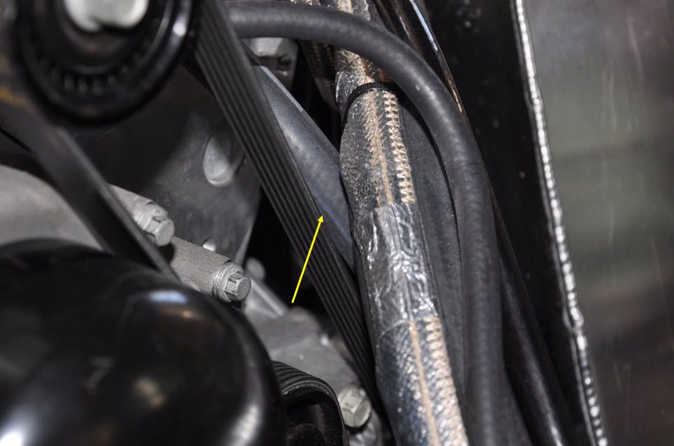
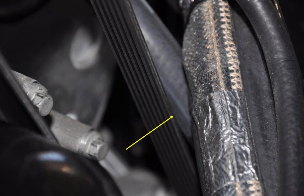
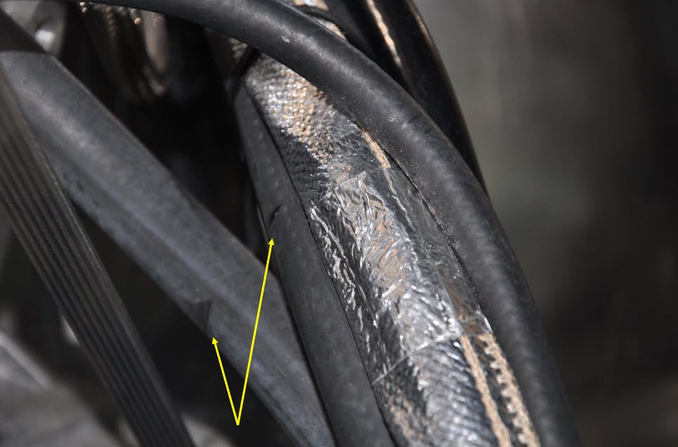
    I pulled the engine cover and firewall out, and started looking around. Everything looked like it should. The belt and crank pulley were both in place and tight. But I noticed that the drive belt looked like it was worn on the front edge on top. It had apparently been rubbing against the heater lines... Take a look at the pictures below. It didn't cut all the way through, but I'm sure that they've been weakend.

    So now I have to figure out the best way to fix them. Do I need to replace both hoses, or can I splice and clamp them? They aren't high pressure lines,

    I also figure that I need to make some sort of bracket that will hold the coolant lines away from the drive belt.

    On to the high water temps... I added some coolant to the overflow tank, and started the engine again. Same thing happened again. I heard the mechanical noise again, about the time that the temp gauge passed 210. It was the pressure going through the overflow pressure cap. At least the crank was still working, and the belt was tight.

    About that time, my neighbor (Ralph) came over and helped me trouble shoot the coolant system...

    We checked the coolant lines from the engine. They were both hot at the water pump; but at the radiator, they were cold. Not cool, or warm; but cold. So we figured that there was an air lock in one of the hoses. After the engine cooled down, I started it up again and let it build a little pressure in the lines. I shut the engine back down and Ralph cracked open the AN connector on the upper radiator side, and bled some of the pressure/steam out of the line. When the engine cooled a little, I added more coolant.

    We went through this routine a couple more times, but couldn't make any progress. Since I am using the overflow tank at the driver's side firewall (above the engine head), I decided to jack the rear of the car as high as I could to try and get the air bubble(s) to move to the highest point.

    We opened the AN connections on the water pump. The Thermostat connection had water leaking out when we loosened the connection. The upper connection on the pump was bone dry. We poured more water into the hose and re-connected it. I fired it up back up.

    This seemed to work a little. At least when I started the engine back up, the hoses going in and out of the radiator got warm. So now I know that the water pump is working, and the thermostat appears to be working also.

    That's as far as I got, but I think we made some progress on it.


    When I pulled the engine cover I saw that the hoses were being cut by the drive belt, after "digging around" a bit. It looks like the engine cover is pressing the hoses into the belt.


    As you can see, the hoses weren't cut completely through, but I think it's enough that they need to be repaired...


    What do you think? Can I just cut the worn sections out and splice and clamp them?

    Thanks,

    Mike
    Last edited by The Stig; 03-19-2013 at 10:10 AM.
    The Stig

    Some say, that I only know two facts about ducks, (both being wrong); and that if I could be bothered, I could solve the "da Vinci Code" in 47 seconds...
    All I know is that I'm called "The Stig".
    GTM #0081

  16. #496
    Senior Member sk7500's Avatar
    Join Date
    Feb 2011
    Posts
    377
    Post Thanks / Like
    Well at least it happened in your shop and not out on the road with your wife in the car. Or at the upholstery shop. Teething paint are never fun. But it's easier when you have the home field advantage.

  17. #497
    Senior Member The Stig's Avatar
    Join Date
    Feb 2011
    Location
    Charlotte, NC
    Posts
    2,004
    Post Thanks / Like
    Quote Originally Posted by sk7500 View Post
    Well at least it happened in your shop and not out on the road with your wife in the car. Or at the upholstery shop. Teething paint are never fun. But it's easier when you have the home field advantage.
    That's exactly what I told my wife. I would much rather find these problems in the garage than somewhere in the middle of nowhere... This would have been much more maddening had it been out on the streets.
    The Stig

    Some say, that I only know two facts about ducks, (both being wrong); and that if I could be bothered, I could solve the "da Vinci Code" in 47 seconds...
    All I know is that I'm called "The Stig".
    GTM #0081

  18. #498
    Senior Member VD2021's Avatar
    Join Date
    Feb 2011
    Location
    Central, FL
    Posts
    958
    Post Thanks / Like
    Blog Entries
    2
    Mike,

    I was looking at some of the pictures of your coolant system plumbing. In a few of the pictures, I see the line that is attached to the head runs down with the 5/8" and 3/4" lines down into the the tunnel (can't tell how far). I assume it goes down and them back up to the overflow tank. If this is the case, you may be trapping air in the head that you want to go to the overflow tank. You may want to route the line off the head directly to the side of the overflow tank, in a manner that keeps it above the head, and see it this helps.
    R/s
    Vidal
    CURRENT STATUS: Interior Rework and Bodywork.
    GenII GTM #331. Delivered (23/9/10)
    BUILD LOG AND WEBSITE:
    http://gtmbuild.weebly.com/ .

  19. #499
    Senior Member
    Join Date
    Feb 2011
    Location
    San Diego
    Posts
    1,961
    Post Thanks / Like
    Vidal makes a good observation. One of the main reasons to run the rear header tank is to avoid having the head line run down hill and then back up to the front mounted tank. I would change that line routing if I were you.

    As to the bleeding, we experience this every time we change an engine on the race car. Which has been frequently lately as we tested three engines this year. You have to give the system time to purge itself and to also move water into the pump housing. The procedure with the header tank installed is much easier than the "stock" arrangement, but it may not be 100% fool proof the first few starts. It still takes some time to get the system bled correctly, but you don't have to keep vacuuming and making a huge mess over and over like you do if yourun the front mounted tank. Then once it is purged, it will work untouched with the exception of maintaining fluid level within the system.

    As far as the lines rubbing? Unfortunately, I believe you know what the answer is. Fix it right and replace and reroute those lines.
    www.myraceshop.com

    GTM solution kits
    Corvette and Race parts

  20. #500
    Senior Member The Stig's Avatar
    Join Date
    Feb 2011
    Location
    Charlotte, NC
    Posts
    2,004
    Post Thanks / Like
    Quote Originally Posted by VD2021 View Post
    Mike,

    I was looking at some of the pictures of your coolant system plumbing. In a few of the pictures, I see the line that is attached to the head runs down with the 5/8" and 3/4" lines down into the the tunnel (can't tell how far). I assume it goes down and them back up to the overflow tank. If this is the case, you may be trapping air in the head that you want to go to the overflow tank. You may want to route the line off the head directly to the side of the overflow tank, in a manner that keeps it above the head, and see it this helps.
    Hi Vidal. The pictures that you reference; were they some place else in this thread, or are you talking about these three? I'll look through and see if I can find pictures that show as much of the hose routings as I can.

    I appreciate the fact that you're giving it some thought. There are quite a few hoses (water & vacuum) running all over the engine... It make sense to make a good diagram of how this is currently set up: even if it's just for my build documentation.

    Thanks Again buddy.

    Mike
    The Stig

    Some say, that I only know two facts about ducks, (both being wrong); and that if I could be bothered, I could solve the "da Vinci Code" in 47 seconds...
    All I know is that I'm called "The Stig".
    GTM #0081

  21. #501
    Senior Member The Stig's Avatar
    Join Date
    Feb 2011
    Location
    Charlotte, NC
    Posts
    2,004
    Post Thanks / Like
    Quote Originally Posted by crash View Post
    Vidal makes a good observation. One of the main reasons to run the rear header tank is to avoid having the head line run down hill and then back up to the front mounted tank. I would change that line routing if I were you.

    As to the bleeding, we experience this every time we change an engine on the race car. Which has been frequently lately as we tested three engines this year. You have to give the system time to purge itself and to also move water into the pump housing. The procedure with the header tank installed is much easier than the "stock" arrangement, but it may not be 100% fool proof the first few starts. It still takes some time to get the system bled correctly, but you don't have to keep vacuuming and making a huge mess over and over like you do if yourun the front mounted tank. Then once it is purged, it will work untouched with the exception of maintaining fluid level within the system.

    As far as the lines rubbing? Unfortunately, I believe you know what the answer is. Fix it right and replace and reroute those lines.
    Hi Mike,

    I figured that the lines needed to be replaced. I just hadn't allowed myself to get into the mindset that there is yet another thing on this car that will now have to be done again...

    But, it looks as though I'll be pulling panels out again in order to get to the front of the engine on both sides, to replace and re-route the hoses...

    I have to say that I'm Not very thrilled about it though.

    I appreciate the observations.

    Mike
    Last edited by The Stig; 11-28-2012 at 08:50 PM.
    The Stig

    Some say, that I only know two facts about ducks, (both being wrong); and that if I could be bothered, I could solve the "da Vinci Code" in 47 seconds...
    All I know is that I'm called "The Stig".
    GTM #0081

  22. #502
    Senior Member VD2021's Avatar
    Join Date
    Feb 2011
    Location
    Central, FL
    Posts
    958
    Post Thanks / Like
    Blog Entries
    2
    Quote Originally Posted by The Stig View Post
    Hi Vidal. The pictures that you reference; were they some place else in this thread, or are you talking about these three? I'll look through and see if I can find pictures that show as much of the hose routings as I can.

    I appreciate the fact that you're giving it some thought. There are quite a few hoses (water & vacuum) running all over the engine... It make sense to make a good diagram of how this is currently set up: even if it's just for my build documentation.

    Thanks Again buddy.

    Mike
    Mike,

    Post "50" (http://thefactoryfiveforum.com/showt...ll=1#post23768) has some pictures of the front of your engine. On these pictures the hose connected to the head is bundled with the lines going down into the tunnel. IIRC it is a 3/8" line. You want it to stay above the head as it runs to the side of the overflow/header tank.
    R/s
    Vidal
    CURRENT STATUS: Interior Rework and Bodywork.
    GenII GTM #331. Delivered (23/9/10)
    BUILD LOG AND WEBSITE:
    http://gtmbuild.weebly.com/ .

  23. #503
    Senior Member The Stig's Avatar
    Join Date
    Feb 2011
    Location
    Charlotte, NC
    Posts
    2,004
    Post Thanks / Like
    Has anyone here used the complete Cooling System Kit that Crash offers? I have most of the parts, from my purchases along the way, but it looks like there are a couple of things that I'm don't have, that I may need. I'm thinking of buying the by-pass kit to add to my re-configuration of the whole cooling system layout and function.

    I've been so burried with my work, that I haven't had a chance to work on the GTM for the past couple of months. I'm finally back to a point that I can spend time out in the garage again. This will be my 1st priority, so I can get the firewall and underbelly buttoned back up.

    So, before that happens, I think I should take the time to rework the the heater hoses from engine to heater coil to radiator.

    If you guys have done this and can give some feedback, I'd really appreciate it.

    Mike "Crash", I'll be placing an order this morning, but I also need your help with a couple of questions...

    You have a PM.

    Thanks,

    Mike
    Last edited by The Stig; 02-24-2013 at 12:27 PM.
    The Stig

    Some say, that I only know two facts about ducks, (both being wrong); and that if I could be bothered, I could solve the "da Vinci Code" in 47 seconds...
    All I know is that I'm called "The Stig".
    GTM #0081

  24. #504
    Senior Member
    Join Date
    Feb 2011
    Location
    San Diego
    Posts
    1,961
    Post Thanks / Like
    PM answered.
    www.myraceshop.com

    GTM solution kits
    Corvette and Race parts

  25. #505
    Senior Member The Stig's Avatar
    Join Date
    Feb 2011
    Location
    Charlotte, NC
    Posts
    2,004
    Post Thanks / Like
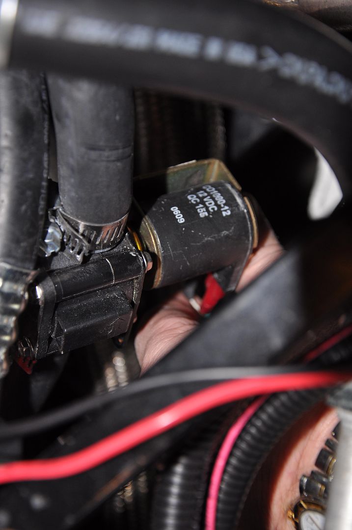
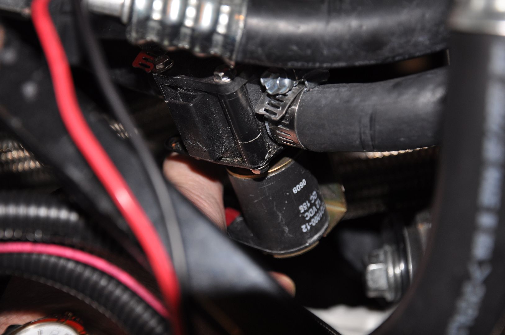
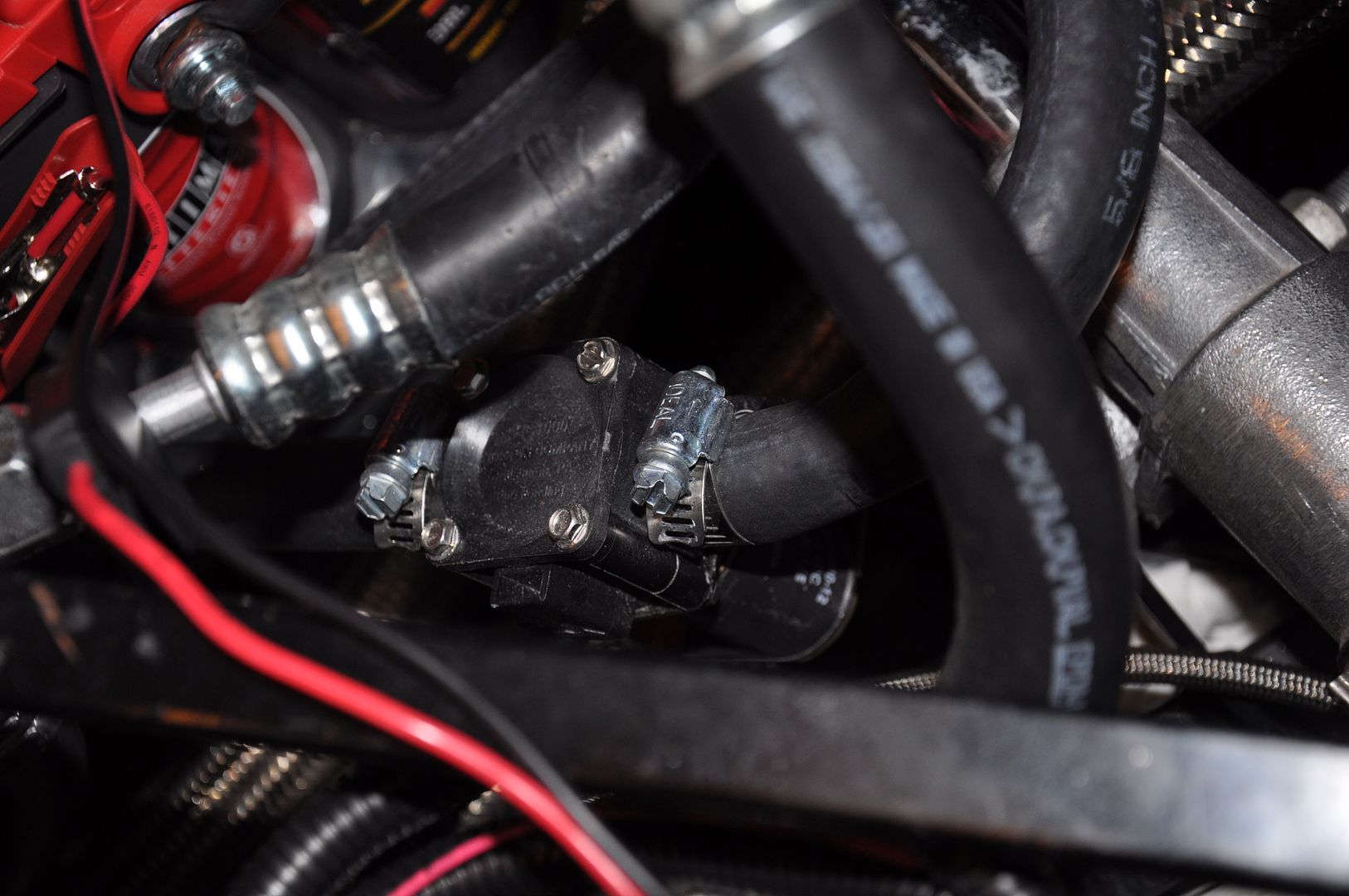
    The weather here in Charlotte was perfect for getting outside in the garage and finally tackling the replacement and re-routing of the heater hoses. When I was under the GTM replacing the heater hoses, I found the Vintage Air Heater Control Valve that Jeff Collins installed when he originally set up the heater hoses. This valve is an one way "in-line" valve that either allows water flow, or blocks it. It is also wired, and I assume that it's wired to the HVAC system wiring.

    Since I knew that would be pulling the hoses and replacing them, I figured it was the perfect opportunity to switch to "Crash's" Heater by-Pass Valve solution. His kit allows for water circulation at all times. When the valve is closed, the water flow simply circulates back to the water pump. When it's open, the water flow runs through the heater core, and then back to the water pump for 100% circulation. Mike's (Crash) kit includes what looks like a vacuum type device that is supposed to be wired to a power source. It uses a vaccum hose that runs from it to the heater by-pass valve, which actually opperates the valve. I'm wondering whether or not I can with this back into the wiring source that the original Vintage Air valve was wired to?

    I tried looking up the Vintage Aire inastallation instructions, but I don't know the model number of the A/C Heater system that Factory Five sells for the GTM, and I don't have the instructions that came with the system.

    I would really appreciate it if some of you guys that are using the Vintage Air HVAC system, as well as Crash's Heater By-Pass Kit, could give me a heads up in terms of how this should be installed and wired. I think I've pretty much figured out the installation of how the hoses should go in, and how they should be routed. But I'm not sure about the wiring piece.

    Here are a couple of picture of the Vintage Air Heater Valve installed.


    I also pulled the overflow tank out so I could reconfigure it.

    I bought a 1/4" barb for the Engine Steam vent to go into the top left of the tank.


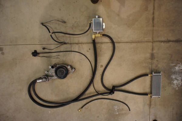
    1. The water pump 3/4" hose will run up and over the front of the engine, across to the T-Fitting on the bottom of the Canton Tank.
    2. The other side of the T-Fitting will be a 90 degree down to a 5/8" barb. 5/8" heater hose from "T-Fitting" to the By-Pass Valve.
    3. The 5/8" Heater Hose from the water pump, and routed to the By-Pass Valve.
    4. 5/8" Heater hose from the By-Pass Valve to the Heater Core.
    5. 5/8" Heater hose from the Heater Core to the By-Pass Valve.


    This mirrors the picture that Crash has posted for the layout / installation of the kit.

    I'll post some pictures of the install as I go through it, for any others who may want/need to see it. (Either tonight or Tomorrow)


    SIDE NOTE
    :

    When I pulled the hoses, I expected to have the system drain it'self of most of the coolant. The water pump and the hoses running from it were dry. The over flow tank, was Dry. When I pulled the hoses from the heater core, they had a "little" coolant in them that drained out, but much less than expected. I haven't pulled the 5/8" hose from the Vintage Air Heater Valve yet, but I'm expecting the same. The Steam vent was corroded and rusted. (I cleaned it back up to get it ready for the new hose to the overflow tank).

    I sure know now, what cause the engine to start over heating. No Water Circulation. But is was whan I traced the hoses back to the HVAC connections that I realized why... The upper Heater Hose connection was only finger tight. It's in a very tight place to be able to get a wrench in and tighten it up. But using on of my "AN fitting" wrenches, I was able to get it tight. I have no idea how long this fitting has been this lose. but at least I know right now that it is tight and should hold the coolant. I'm also wondering whether or not the in-line heater valve possibly being in the "closed" position, combined with the loose heater hose connection on the HVAC is what cause the all of the components to be DRY. Understand that the reason for my surprise is due to the fact that I never saw ANY fluid on the garage floor beneath the GTM. Strange...

    I'm just glad that I found this now, while I still had the bottom panels off, and before I had taken off for a GTM road trip... I'm also glad that I found this before something bad happend to the engine. Luckily, everything is Ok. But it could have gotten very expensive, Very fast.

    I believe that things happen for a reason, but that doesn't make them any less frustrating. And for now, I think I'll just keep it at that.

    Everyone be sure and double check your connections BEFORE you buttom up the bottom panels!!!!

    Mike
    Last edited by The Stig; 03-10-2013 at 11:55 AM.
    The Stig

    Some say, that I only know two facts about ducks, (both being wrong); and that if I could be bothered, I could solve the "da Vinci Code" in 47 seconds...
    All I know is that I'm called "The Stig".
    GTM #0081

  26. #506
    Senior Member The Stig's Avatar
    Join Date
    Feb 2011
    Location
    Charlotte, NC
    Posts
    2,004
    Post Thanks / Like
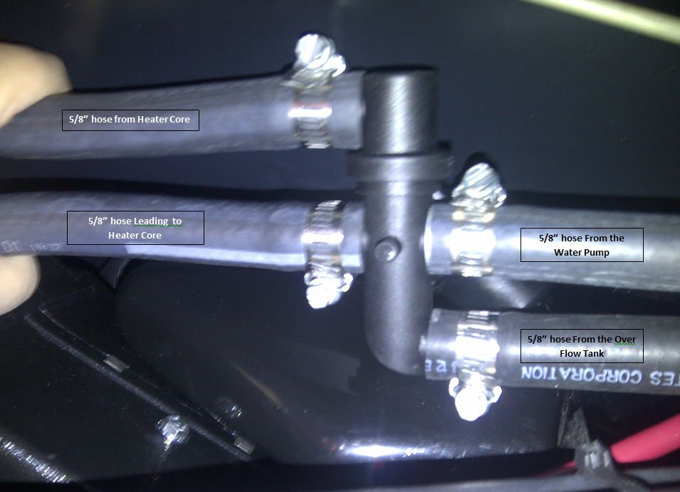
    I pulled the Vintage Air Heater Valve out, and ran new hoses throughout the HVAC system, using the new Heater By-Pass Valve from "My Race Shop".


    I connected the hoses to the valve in the way that seemed to make the best sense to me...


    The 5/8" heater hose from the water pump, runs into the "center" connection. The other side of the "center" connection is a 5/8" hose that runs into the Heater Core. The Heater Core Exit hose (5/8") runs to the outside connection of the By-Pass Valve. The 5/8" hose from the Over flow tank, runs into the outside connection of the By-Pass Valve.

    I haven't run the wiring from the old Heater Valve to the new Vacuum Solenoid yet. I'll try to take care of that tomorrow afternoon. According to the install instructions, there is a vacuum hose that runs from the Vacuum solendoid to the intake manifold. But I haven't figured out where that connection is made...
    Last edited by The Stig; 03-11-2013 at 08:38 AM.
    The Stig

    Some say, that I only know two facts about ducks, (both being wrong); and that if I could be bothered, I could solve the "da Vinci Code" in 47 seconds...
    All I know is that I'm called "The Stig".
    GTM #0081

  27. #507
    Senior Member sk7500's Avatar
    Join Date
    Feb 2011
    Posts
    377
    Post Thanks / Like
    Rework is never as much fun as the initial building but a lot more fun than pushing a broken supercar.
    I've done what you're doing and it works great. I didn't find a good way to route the hoses at the catch tank with the supplied fittings. One more thing on the list of things to do.

  28. #508
    Senior Member
    Join Date
    Feb 2011
    Location
    San Diego
    Posts
    1,961
    Post Thanks / Like
    sk7500- Good info to know. If you would please, post some pics of what you ultimately end up with so I can consider modifications to the items I include in the kits.

    Thanks.
    www.myraceshop.com

    GTM solution kits
    Corvette and Race parts

  29. #509
    Senior Member VD2021's Avatar
    Join Date
    Feb 2011
    Location
    Central, FL
    Posts
    958
    Post Thanks / Like
    Blog Entries
    2
    Quote Originally Posted by sk7500 View Post
    Rework is never as much fun as the initial building but a lot more fun than pushing a broken supercar.
    I've done what you're doing and it works great. I didn't find a good way to route the hoses at the catch tank with the supplied fittings. One more thing on the list of things to do.
    Yeah,

    I found those hose runs to be a challenge also. I have different fittings for the bottom of the tank and I actually ended up going through the side of the aluminum panel. Maybe these pics will help someone.
    Attached Images Attached Images
    Last edited by VD2021; 03-12-2013 at 11:08 AM.
    R/s
    Vidal
    CURRENT STATUS: Interior Rework and Bodywork.
    GenII GTM #331. Delivered (23/9/10)
    BUILD LOG AND WEBSITE:
    http://gtmbuild.weebly.com/ .

  30. #510
    Senior Member The Stig's Avatar
    Join Date
    Feb 2011
    Location
    Charlotte, NC
    Posts
    2,004
    Post Thanks / Like
    Quote Originally Posted by VD2021 View Post
    Yeah,

    I found those hose runs to be a challenge also. I have different fittings for the bottom of the tank and I actually ended up going through the side of the aluminum panel. Maybe these pics will help someone.
    The 5/8" hose from the water pump to the by-pass valve:
    I ran that hose in a loop back under the engine and a/c Compressor and into the tunnel, in an attempt to keep it as horizontal as I can. Hopefully by doing it will help to prevent air pockets.

    For the 5/8" hose coming back from the by-pass valve to the over flow tank:
    I started to cut through the aluminum panel as well, but I ran it back along the engine cover frame on the driver's side and then made a loop back to the T-Fitting. I'll use hose connectors as you did, to keep the hose next to the frame and away from the serpentine belt.

    The 3/4" heater line from the water pump:
    This line runs accross the engine (between the intake manifold and the accessory brackets), and straight into the 3/4" barb on the T-Fitting. I have my steam vent routed exactly as you did yours.

    I plan to run a 3/8" hose from the Canton overflow tank (neck):
    to the top right (overflow) of the radiator.

    There is also a 1/2" connection (top right of the radiator) that I can add the draincock to, in order to release any trapped air from the radiator.

    OR... I could add the original Corvette Overflow tank, to use as a purge tank. Is anyone else doing that?

    One thing that I was concerned about, was flow direction through the heater core. I couldn't find any place that mentioned which line should be connected to which heater core connection. So I called Vintage Air. I was a little surprised to find out that there is no particular flow direction (in/out). So it doesn't matter how they're connected to the heater core connections.

    So all I need to do now, is make the correct wiring connections for the Vacuum Solenoid, and figure out where the vacuum line runs from that solenoid to the intake manifold...

    Thanks Vidal.
    Last edited by The Stig; 03-12-2013 at 01:14 PM.
    The Stig

    Some say, that I only know two facts about ducks, (both being wrong); and that if I could be bothered, I could solve the "da Vinci Code" in 47 seconds...
    All I know is that I'm called "The Stig".
    GTM #0081

  31. #511
    Senior Member The Stig's Avatar
    Join Date
    Feb 2011
    Location
    Charlotte, NC
    Posts
    2,004
    Post Thanks / Like
    Quote Originally Posted by sk7500 View Post
    Rework is never as much fun as the initial building but a lot more fun than pushing a broken supercar.
    I've done what you're doing and it works great. I didn't find a good way to route the hoses at the catch tank with the supplied fittings. One more thing on the list of things to do.
    Hi Steve,

    That's pretty much the same train of thought that I try to hang onto. Better to find it and fix it in the garage that on the side of the highway with all the picture takers laughing at the broken down Super Car.

    As far as the fittings, I have to agree. I didn't buy the brass fittings kit to go along with the Header Tank kit. I used what was already there. My issue is that Like most of us, I have the post pump fuel filter mounted on the deck just below the overflow tank. I also have the Cold Air intake tube running through the same space. So I'm trying to work inside of those pieces. It's not so bad as long as you have the cockpit wall out of the car.

    I guess the thing that got my attention more than anything else, is the fact that the upper heater core connection was only finger tight. No coolant is about the easiest way that i know of to cook a brand new engine.

    But... I found it, and now it's fixed. $200.00 vs. $8,000.00.

    Life is good.
    The Stig

    Some say, that I only know two facts about ducks, (both being wrong); and that if I could be bothered, I could solve the "da Vinci Code" in 47 seconds...
    All I know is that I'm called "The Stig".
    GTM #0081

  32. #512
    Senior Member sk7500's Avatar
    Join Date
    Feb 2011
    Posts
    377
    Post Thanks / Like
    I haven't talked with Crash yet, but I think I'm going to pull the tank and weld in two bungs on the side of the tank so I can eliminate the brass T on the bottom of the tank. Then I can plug the two hoses onto straight fittings and get rid of u turn the hose is trying to make.
    I'm working on our fresh air intake system right now. But I'll have to deal with the hose routing before doing any serious driving.

  33. #513
    Senior Member
    Join Date
    Feb 2011
    Location
    San Diego
    Posts
    1,961
    Post Thanks / Like
    Makes sense to me, and is the way we did it on the prototype. Then I recreated it as best I could with fittings because if I had to charge people for the pieces and time to do the welding then no one would likely want to buy it. I figured the people that have the TIG capability will just buy a tank and weld bungs and do it that way as it is cleaner and simpler, but the kit is designed for those without the welding capability so that they can still make the cooling system "right".

    Quote Originally Posted by sk7500 View Post
    I haven't talked with Crash yet, but I think I'm going to pull the tank and weld in two bungs on the side of the tank so I can eliminate the brass T on the bottom of the tank. Then I can plug the two hoses onto straight fittings and get rid of u turn the hose is trying to make.
    I'm working on our fresh air intake system right now. But I'll have to deal with the hose routing before doing any serious driving.
    www.myraceshop.com

    GTM solution kits
    Corvette and Race parts

  34. #514
    Senior Member The Stig's Avatar
    Join Date
    Feb 2011
    Location
    Charlotte, NC
    Posts
    2,004
    Post Thanks / Like
    Special thanks to Vidal. I appreciate that you're always willing to make yourself available to help. Between you, David Borden, and Gary Cheney; you've all been highly instrumental in helping me keep my head straight when my frustration levels seem to get the best of me. I'm seeing light at the end of the tunnel again.

    When we get these cars finished and all the "bugs" worked out, we really need to follow up with our plans to meet up, hang out and compare notes. Maybe we can get Keith and a couple of others from the area in the mix as well, and have a mini GTM car show at some restaurant in the Orlando area. That would be a sweet site. It's something to aim for at least.

    Thanks again Buddy.

    Mike
    The Stig

    Some say, that I only know two facts about ducks, (both being wrong); and that if I could be bothered, I could solve the "da Vinci Code" in 47 seconds...
    All I know is that I'm called "The Stig".
    GTM #0081

  35. #515
    Senior Member VD2021's Avatar
    Join Date
    Feb 2011
    Location
    Central, FL
    Posts
    958
    Post Thanks / Like
    Blog Entries
    2
    Quote Originally Posted by The Stig View Post
    When we get these cars finished and all the "bugs" worked out, we really need to follow up with our plans to meet up, hang out and compare notes. Maybe we can get Keith and a couple of others from the area in the mix as well, and have a mini GTM car show at some restaurant in the Orlando area. That would be a sweet site. It's something to aim for at least.

    Thanks again Buddy.

    Mike
    Mike,

    That would be too cool:.

    I'm looking forward to it.
    R/s
    Vidal
    CURRENT STATUS: Interior Rework and Bodywork.
    GenII GTM #331. Delivered (23/9/10)
    BUILD LOG AND WEBSITE:
    http://gtmbuild.weebly.com/ .

  36. #516
    Senior Member sk7500's Avatar
    Join Date
    Feb 2011
    Posts
    377
    Post Thanks / Like
    Quote Originally Posted by crash View Post
    Makes sense to me, and is the way we did it on the prototype. Then I recreated it as best I could with fittings because if I had to charge people for the pieces and time to do the welding then no one would likely want to buy it. I figured the people that have the TIG capability will just buy a tank and weld bungs and do it that way as it is cleaner and simpler, but the kit is designed for those without the welding capability so that they can still make the cooling system "right".
    Crash,
    Your kit is perfect the way it is. To be honest I don't know if we would have spent more money for a more expensive kit not knowing what I know now. But you know what they say about hindsight? So leave your kit the way it is. Maybe some upgrade options in the future. An all electric valve would eliminate the hassle of running one more hose and trying to figure out where to plug it into the motor. I know you're working on and it'll be great if you can make that option available.
    Steve

  37. #517
    Senior Member The Stig's Avatar
    Join Date
    Feb 2011
    Location
    Charlotte, NC
    Posts
    2,004
    Post Thanks / Like
    Finished the replacing the heater hoses and re-routing them in order to minimize air pockets in the system. I went ahead and installed Crash's heater by-pass valve kit. I had a minor irrigation system emergency that had to be taken care or. (My wifes flowers weren't getting enough water). Turns out that the company that recently replaced my home A/C units, knocked out one of the control wires to the irrigation valves. That's fixed, and the flowers are getting water again, so life is good.

    However, I ran out of time to get the vacuum pump solenoid wired. I'll do that this weekend when I'm back.

    It feels good to get back outside and make some progress here and there.

    Mike
    Last edited by The Stig; 04-27-2013 at 09:25 PM.
    The Stig

    Some say, that I only know two facts about ducks, (both being wrong); and that if I could be bothered, I could solve the "da Vinci Code" in 47 seconds...
    All I know is that I'm called "The Stig".
    GTM #0081

  38. #518
    Member
    Join Date
    Feb 2011
    Posts
    42
    Post Thanks / Like
    Ditto, just did the same thing with my GTM. It's kind of a hassle but well worth it to avoid the air pockets and overheating. Shane (VRaptor) is now making a bracket to weld onto the frame that will relocate the Corvette plastic tank to the back, t FYI.
    Radkat

  39. #519
    LCD Gauges's Avatar
    Join Date
    Apr 2011
    Location
    Toronto, Ontario
    Posts
    1,545
    Post Thanks / Like
    Blog Entries
    3
    It has been a while since I've sat on this forum to catch-up with everyone's build. It seems like you're working through the pitfalls nicely. The new interior plan that you describe is going to be killer!From what I recall, you don't have the car registered yet, correct? If so, how close are you to zipping up the registration?
    Custom LCD Gauges , Data Loggers, Control Touch Screens
    www.LCDdash.com \\ 647-522-9953 \\ Voice & Text
    Proud new owner of GTM Gen 1., #105 - 08/27/11
    LQ9 Powered, G96.00 6 speed transaxle

  40. #520
    Senior Member The Stig's Avatar
    Join Date
    Feb 2011
    Location
    Charlotte, NC
    Posts
    2,004
    Post Thanks / Like
    Quote Originally Posted by 00SS_M6LS1 View Post
    It has been a while since I've sat on this forum to catch-up with everyone's build. It seems like you're working through the pitfalls nicely. The new interior plan that you describe is going to be killer!From what I recall, you don't have the car registered yet, correct? If so, how close are you to zipping up the registration?
    Hey Bud. All paperwork is complete, inspections have been done, and just needs to be sent in (with a fairly large check) for processing. I hope to have that completed by the end of the month. From what I understand, it's more of a formality at this point. but I've heard that before...

    Mike
    Last edited by The Stig; 03-18-2013 at 03:33 PM.
    The Stig

    Some say, that I only know two facts about ducks, (both being wrong); and that if I could be bothered, I could solve the "da Vinci Code" in 47 seconds...
    All I know is that I'm called "The Stig".
    GTM #0081

Page 13 of 51 FirstFirst ... 3111213141523 ... LastLast

Tags for this Thread

Posting Permissions

  • You may not post new threads
  • You may not post replies
  • You may not post attachments
  • You may not edit your posts
  •  

Stewart Transport

Visit our community sponsor