Forte's

Visit our community sponsor

Thanks Thanks:  0
Likes Likes:  0
Page 4 of 7 FirstFirst ... 23456 ... LastLast
Results 121 to 160 of 259

Thread: De-powering the steering rack, plus more to come on rebuilding wrx parts

  1. #121
    Senior Member Xusia's Avatar
    Join Date
    Oct 2011
    Location
    Eugene, OR, USA
    Posts
    2,343
    Post Thanks / Like
    For those who - like me - don't understand the finer workings of power steering, I found a series of video (3 parts, all very short) that explain it well:

    Part 1

    Part 2

    Part 3

  2. #122
    Senior Member
    Join Date
    Mar 2011
    Location
    Houston
    Posts
    477
    Post Thanks / Like
    Quote Originally Posted by Xusia View Post
    For those who - like me - don't understand the finer workings of power steering, I found a series of video (3 parts, all very short) that explain it well:

    Part 1

    Part 2

    Part 3
    Very clear.....Thanks for finding and posting Xusia

  3. #123
    818 builder metalmaker12's Avatar
    Join Date
    Mar 2012
    Location
    Exeter R.I
    Posts
    2,834
    Post Thanks / Like
    Blog Entries
    1
    Here is video 1 showing the 1/8 play in the 2005-2007 steering rack pinion, shaft. I finally got my computer and go-pro to work here. It was like 7am so don't make to much fun of me
    Last edited by metalmaker12; 05-05-2013 at 09:27 PM.

  4. #124
    818 builder metalmaker12's Avatar
    Join Date
    Mar 2012
    Location
    Exeter R.I
    Posts
    2,834
    Post Thanks / Like
    Blog Entries
    1
    Here is the final outcome. I plug welded some other spots, but in my opinion this is the best option. It was not super clean, since I was in the middle a of a huge side welding job, so the weld is ok, but not my best work, and I had to really monitor the heat input. Prior to welding I dipped the shaft in acetone briefly to try to get some grease out. I also used some degreaser. It got like 90% out, and If I had more time I would have gotten it 100% clean.

    Tools: Tig welder, 1/16 sharp tungsten, #6 cup for good gas coverage, 309, or 70s-3 steel wire, and run at about 65-80amps


  5. #125
    Senior Member RM1SepEx's Avatar
    Join Date
    Jul 2011
    Location
    Freeport, ME
    Posts
    3,801
    Post Thanks / Like
    Thanks Chris! When I get it back I'll see what I can do to make up a crude fixture and compare forced deflection and rotation when installed in my rack both with the modified piece and with with the stock valve and pinion assembly.

  6. #126
    Senior Member FFR-ADV's Avatar
    Join Date
    Oct 2011
    Location
    NH
    Posts
    597
    Post Thanks / Like
    Thank you for doing this Chris,

    Great job!

    Steve

  7. #127
    Member
    Join Date
    Mar 2012
    Posts
    57
    Post Thanks / Like
    really appreciate the video.

    Thanks

  8. #128
    Senior Member Xusia's Avatar
    Join Date
    Oct 2011
    Location
    Eugene, OR, USA
    Posts
    2,343
    Post Thanks / Like
    Totally, thanks!

  9. #129
    fasterer and furiouser longislandwrx's Avatar
    Join Date
    Aug 2012
    Location
    Long Island
    Posts
    2,540
    Post Thanks / Like
    Blog Entries
    6
    Send it back to RM1SepEx and see if it fits.! nice jorb.
    A well stocked beverage fridge is the key to any successful project.

  10. #130
    818 builder metalmaker12's Avatar
    Join Date
    Mar 2012
    Location
    Exeter R.I
    Posts
    2,834
    Post Thanks / Like
    Blog Entries
    1
    Thanks guys, it was no biggy, plus I got to learn how to upload my go-pro. I cannot wait to be uploading build videos, and better yet my own 0-60, 80,,,100, 120 and some track stuff down the line etc. I will be doing the 2002-2004 pinion shaft at some point also. I will be sending out the shaft for fitment within a week or two.
    Any questions PM me

  11. #131
    Mechie3's Avatar
    Join Date
    May 2012
    Location
    Indianapolis
    Posts
    5,174
    Post Thanks / Like
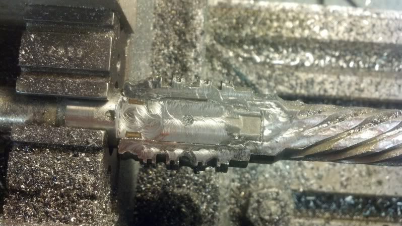
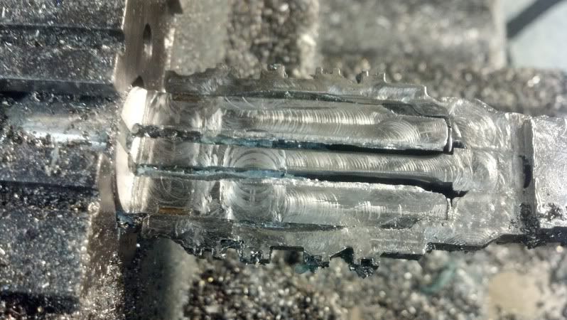
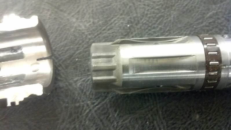
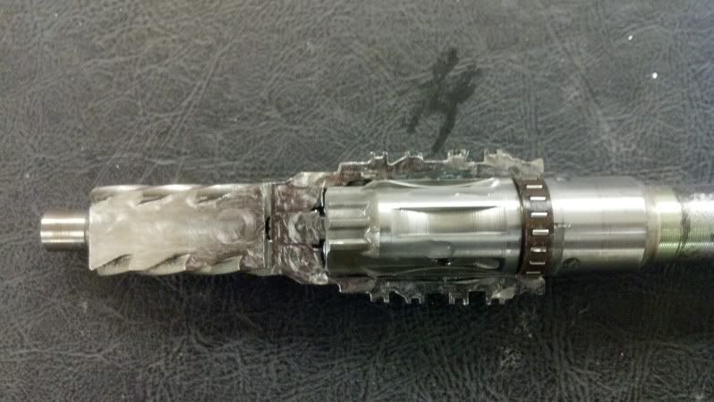
    Thanks to a donation from Freds, here is an inside look at the 06 WRX spool valve and pinion assy. Prior to sending it to me he filled it with epoxy. I couldn't get it to move using vicegrips, but longevity is unknown. Seems like it can't hurt to try.

    Starting to cut it open. You can see the differences in the two metals. The outside is case hardened, the inside is much softer.


    View of the torsion rod. You can calculate angle of twist from TL/JG = Angle (T= torque, L= length, J=2nd polar moment of inertia, G= material strength).


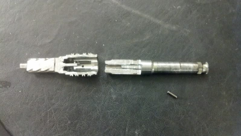
    I cut the torsion rod in half to remove the two halves. The torsion bar is pressed into teh lower piece and pinned into the top piece.


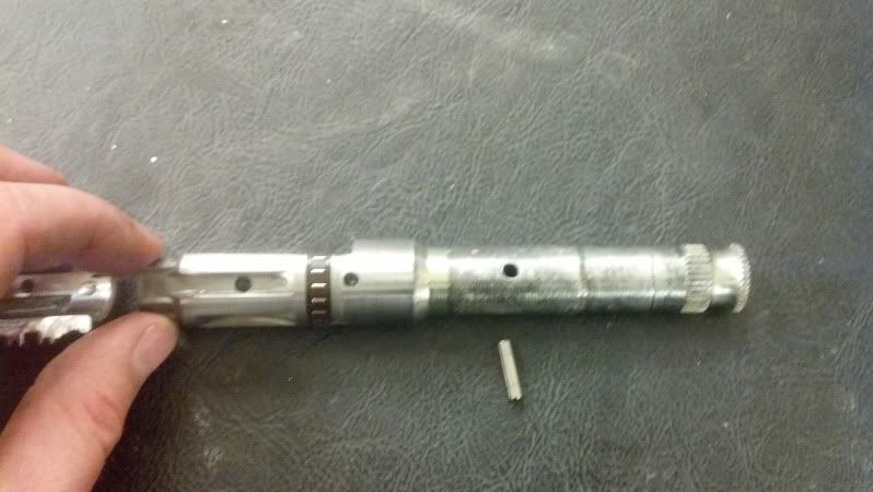
    There is an accessible pin. You can press this out (start with a short pin so it self supports to start, then use a long pin) and it will unlock the torsion bar. Because of all the epoxy in here, I coldn't get the cut torsion bar half out yet.


    The splines. These are located at the bottom. Just under the splin is a thrust journal bearing.


    Top half inserted flipped over to show relative positions. There is a small bearing on the inside as well.


    The bearing race is indeed part of the spool/pinion body which is why I couldn't press it off and the inside dimenions of the bearing didn't match published ID's for that bearing size. The best way to go is to weld the top like metalmaker did if you're careful and don't warp the bearing race. Another option is to cross drill the assy and press/weld in a pin through the entire assy. A third option is to drill through the middle of the spool valve (remove the upper input shaft first) around the circumference and create spot welds. The last option would be to remove the input shaft, cut off the bearing race portion plus a little extra. Reinsert the input shaft and pin it in place, weld it together, then press a standard bearing over the top (if you can find it in the correct size).
    Last edited by Mechie3; 05-21-2013 at 02:06 PM.
    Zero Decibel Motorsports
    Check out my new website!
    www.zerodecibelmotorsports.com
    www.facebook.com/zero.decibel.motorsports

  12. #132
    Senior Member
    Join Date
    Mar 2011
    Location
    Houston
    Posts
    477
    Post Thanks / Like
    Thanks Mechie3...I'm a visual sort of person and am very pleased to see the guts

    fred

  13. #133
    fasterer and furiouser longislandwrx's Avatar
    Join Date
    Aug 2012
    Location
    Long Island
    Posts
    2,540
    Post Thanks / Like
    Blog Entries
    6
    Looks like the penetration of the epoxy was pretty good. I'm impressed.

    Not sure how much force you could apply to this with your hands. I think you'd have a broken wrist before this would fail due to a pothole/curb impact. Repeated vibrations might wear this out eventually but I actually think it might have survived for a while.
    A well stocked beverage fridge is the key to any successful project.

  14. #134
    Senior Member RM1SepEx's Avatar
    Join Date
    Jul 2011
    Location
    Freeport, ME
    Posts
    3,801
    Post Thanks / Like
    nice work! so the large spline shown in the last photo carries the load and "flops" from edge to edge when you go from left to right etc.. and the relatively little (dia?) torsion bar makes it smoothly transition vs the loose on center flop of the Miata design.

    If you can drive out the pin and take it apart and fill that area with the spline with JB weld and reassemble
    it should work well...

    Metalmaker just sent mine back, I'll see what I can do to set up a test setup to compare stock vs welded

  15. #135
    Mechie3's Avatar
    Join Date
    May 2012
    Location
    Indianapolis
    Posts
    5,174
    Post Thanks / Like
    I'll have to go measure the torsion bar. It was around 3/16" or so. The epoxy did get rather good penetration. It took me a second to realize it stunk while machining because of the epoxy. To get it out, I had to use a pick and a hammer. Even then, I didn't get it all out, just enough to take it apart. JB weld might be better then epoxy. Not sure how brittle jb weld is when cured vs epoxy since I've only used it once to plug a hole.
    Zero Decibel Motorsports
    Check out my new website!
    www.zerodecibelmotorsports.com
    www.facebook.com/zero.decibel.motorsports

  16. #136
    fasterer and furiouser longislandwrx's Avatar
    Join Date
    Aug 2012
    Location
    Long Island
    Posts
    2,540
    Post Thanks / Like
    Blog Entries
    6
    So can you press that pin out, separate the sections, glob it up with JB weld/Epoxy insert the shaft and repin? or do you need to mill to get access to that pin?

    also is that needle? bearing plastic? could you crack that out, and really get in there with the welder?
    Last edited by longislandwrx; 05-21-2013 at 03:36 PM.
    A well stocked beverage fridge is the key to any successful project.

  17. #137
    Mechie3's Avatar
    Join Date
    May 2012
    Location
    Indianapolis
    Posts
    5,174
    Post Thanks / Like
    The needle bearing is some sort of polymer/fiber piece. Looks like a phenolic.

    The pin is very accessible, no welding necessary. The only hard part is getting a pin to press out the existing pin to stand up. I used a really short pin so that it could only tip so much. After I pressed it out .125", I got a long pin and finished pressing it out.

    Fred just used a syringe to fill it with epoxy and it filled just about every available spot. I don't know if JB weld flows as well as what he used.
    Zero Decibel Motorsports
    Check out my new website!
    www.zerodecibelmotorsports.com
    www.facebook.com/zero.decibel.motorsports

  18. #138
    818 builder metalmaker12's Avatar
    Join Date
    Mar 2012
    Location
    Exeter R.I
    Posts
    2,834
    Post Thanks / Like
    Blog Entries
    1
    Nice to have a machine shop you can use. I knew I should have tried harder with pushing out that pin, but I was set on welding. My way did work, but lets see what we can do to glue one back up and make it hold as long as weld. Nice work Mechie!!
    Last edited by metalmaker12; 05-21-2013 at 04:56 PM.

  19. #139
    Senior Member
    Join Date
    Mar 2011
    Location
    Houston
    Posts
    477
    Post Thanks / Like

    Filling the voids

    I believe JB Weld is epoxy with some powdered metal/steel filler. I bought and looked at it, but it will not flow into the innards of the assembly.

    Also, I believe that since every cavity was totally filled with epoxy, even if it "crumbled"...the crumbs would have no where to go. I feel even if you could fill the voids completely with fine grained sand, it would be locked up. There is simply no place to squeeze it to....and what the hey they glue aircraft together with this sort of stuff.

    I mentioned to Mechie3 that even if it vaporized and did magically disappear you end up with the "normal slop"...no crisis, and then one could do any of the other suggested ways of locking the unit up.

    I have chosen the epoxy injection, which cannot/does not potentially harm the inner race of the bearing (which admittedly is not a normally loaded running bearing)...or potentially weakening the overall concentric sleeves.

    I don't think any of the solutions is "bad"...take your pick.
    Last edited by freds; 05-21-2013 at 05:35 PM.

  20. #140
    818 builder metalmaker12's Avatar
    Join Date
    Mar 2012
    Location
    Exeter R.I
    Posts
    2,834
    Post Thanks / Like
    Blog Entries
    1
    +1 .? I agree, weld, or glue were good

  21. #141
    Senior Member
    Join Date
    Mar 2011
    Location
    Houston
    Posts
    477
    Post Thanks / Like
    Quote Originally Posted by metalmaker12 View Post
    +1 .? I agree, weld, or glue were good
    Hi mm12, not to be a pain...just to clarify the way I think of it...
    Using the epoxy is not really to glue the parts together, but to insert something in-compressible between, particularly, the splines....which eliminates the possibility of there being any "slop". The fact that it will also act as "glue" between all the parts is a bonus.

  22. #142
    818 builder metalmaker12's Avatar
    Join Date
    Mar 2012
    Location
    Exeter R.I
    Posts
    2,834
    Post Thanks / Like
    Blog Entries
    1
    no pain here, (I meant epoxy) were all 818 brothers learning together and trying to come up with ways to mod stuff. It is all constructive to me. Mechies dissection was a interesting look into the pinion. The epoxy will work well and I understand about it working as a substance that will wedge between the inners of the pinion shaft as well as stick to everything.

  23. #143
    Senior Member DodgyTim's Avatar
    Join Date
    Apr 2013
    Location
    Brisbane, Australia
    Posts
    289
    Post Thanks / Like
    I had intended to try the epoxy and measure and post the results seems I have been beaten off the mark...
    A normal marine grade epoxy used for boat building has a compressive strength of about 12,300 psi and without much searching I've found other grades up to 15,800 psi.
    The big question for me was getting the cavity fully filled, so it acts like a wedge instead of a glue. The sectioned photos are great, now i'm reasonably confident the epoxy solution will work
    Thanks for the great work Mechie3

  24. #144
    Senior Member
    Join Date
    Apr 2012
    Posts
    438
    Post Thanks / Like
    I'm still trying to find a solid answer if the quick steering internals of the JDM Spec-C steering rack will swap into a USDM rack. I've read conflicting information on the internet (as usual).

  25. #145
    Senior Member JAubin's Avatar
    Join Date
    Mar 2012
    Location
    Goffstown, NH
    Posts
    232
    Post Thanks / Like
    Thanks for the research into this Metal and Mechie, both parts that were investigated were 05+ right? Any idea if an '02 rack could use basically the same process?

  26. #146
    Senior Member
    Join Date
    Mar 2011
    Location
    Houston
    Posts
    477
    Post Thanks / Like
    Quote Originally Posted by DodgyTim View Post
    I had intended to try the epoxy and measure and post the results seems I have been beaten off the mark...
    A normal marine grade epoxy used for boat building has a compressive strength of about 12,300 psi and without much searching I've found other grades up to 15,800 psi.
    The big question for me was getting the cavity fully filled, so it acts like a wedge instead of a glue. The sectioned photos are great, now i'm reasonably confident the epoxy solution will work
    Thanks for the great work Mechie3
    To fill the voids fully a fairly low viscosity product is necessary.
    Since the epoxy, when in-between the splines and filling all spaces, is physically restrained, I reasoned that 3,200 psi compressive strength was adequate. It cannot go anywhere even if its normal compressive stress were to be exceeded.

    The one I used in the unit mechie opened, and on my own depowered unit is

    http://www.loctiteproducts.com/p/epx...x-5-Minute.htm

    It flows pretty well and cures quickly. I injected it into every orifice until it started to come out of other orifices then I kept moving it around as it cured so that none of it could run out before it set-up.

  27. #147
    Mechie3's Avatar
    Join Date
    May 2012
    Location
    Indianapolis
    Posts
    5,174
    Post Thanks / Like
    Quote Originally Posted by JAubin View Post
    Thanks for the research into this Metal and Mechie, both parts that were investigated were 05+ right? Any idea if an '02 rack could use basically the same process?
    These are different. They essentially unbolt IIRC. I have one at home I can look at, or I think metalmaker already did one.
    Zero Decibel Motorsports
    Check out my new website!
    www.zerodecibelmotorsports.com
    www.facebook.com/zero.decibel.motorsports

  28. #148
    fasterer and furiouser longislandwrx's Avatar
    Join Date
    Aug 2012
    Location
    Long Island
    Posts
    2,540
    Post Thanks / Like
    Blog Entries
    6
    Quote Originally Posted by freds View Post
    I injected it into every orifice until it started to come out of other orifices then I kept moving it around as it cured so that none of it could run out before it set-up.
    looking at the pictures, I don't see what hole you used to get this epoxy into the assembly.
    A well stocked beverage fridge is the key to any successful project.

  29. #149
    Senior Member
    Join Date
    Mar 2011
    Location
    Houston
    Posts
    477
    Post Thanks / Like
    Valve-Pinion.jpg

    Every hole...I mean everyone you can see in this photo, and all those around the pinion that you cannot see, including the holes above (to the right in the pic.)of the bearing....Just don't dribble any into the bearing..ha-ha.
    And I held it vertically to be sure the epoxy ran down into the splines..Then kept moving it around to let gravity do its job as it set.

    Quote Originally Posted by longislandwrx View Post
    looking at the pictures, I don't see what hole you used to get this epoxy into the assembly.
    .
    Last edited by freds; 05-22-2013 at 10:20 AM.

  30. #150
    Senior Member RM1SepEx's Avatar
    Join Date
    Jul 2011
    Location
    Freeport, ME
    Posts
    3,801
    Post Thanks / Like
    Quote Originally Posted by longislandwrx View Post
    looking at the pictures, I don't see what hole you used to get this epoxy into the assembly.
    he injected it into all of the oil holes that are used to assist the rack to move/turn the wheels... makes very good sense... and he is correct even if it does degrade, where can it go? worst case it finds a way out and you are back to a depowered rack with the slight torsional movement when the torsion bar alows the part to rotate..

    I'd just like to see something a bit stronger... however viscosity is key if you inject through the holes.

    I'd like someone to try driving out the pin, separate the parts, insert JB Weld into the spline area, put them back together and replace the pin...

    Received the welded unit back today... not sure when I'll get to testing it for movement, I've got some honeydoos and a sick dad

  31. #151
    fasterer and furiouser longislandwrx's Avatar
    Join Date
    Aug 2012
    Location
    Long Island
    Posts
    2,540
    Post Thanks / Like
    Blog Entries
    6
    Quote Originally Posted by freds View Post
    Valve-Pinion.jpg

    Every hole...I mean everyone you can see in this photo.
    Do you have pictures of your other glued one before you put it back together?
    A well stocked beverage fridge is the key to any successful project.

  32. #152
    Senior Member
    Join Date
    Mar 2011
    Location
    Houston
    Posts
    477
    Post Thanks / Like
    Quote Originally Posted by longislandwrx View Post
    Do you have pictures of your other glued one before you put it back together?
    124 is a photo of the one mechie cut open which shows the epoxy in one particular hole quite clearly. Each and every hole on the one I put back in my assembly looked pretty much just like that.

    I masked off the seals and the bearing openings carefully, and cleaned off the tiny amounts of drool that I intentionally caused by injecting in each hole until it started to come out of the other hole(s) Just like greasing a bearing.
    ...but holding it a little off vertical to make sure the epoxy would run into the splines..as earlier described.
    I am quite sure, especially after seeing my guinea pig cut open by mechie, that every void is filled.

    20130420_080124.jpg

  33. #153
    818 builder metalmaker12's Avatar
    Join Date
    Mar 2012
    Location
    Exeter R.I
    Posts
    2,834
    Post Thanks / Like
    Blog Entries
    1
    The epoxy seemed to work well and I do have an 02, but it is fully assembled, maybe I will take it apart.

  34. #154
    Senior Member
    Join Date
    Mar 2011
    Location
    Houston
    Posts
    477
    Post Thanks / Like
    Quote Originally Posted by metalmaker12 View Post
    The epoxy seemed to work well and I do have an 02, but it is fully assembled, maybe I will take it apart.
    Guys, I forgot to add...I flushed out the insides several times...immersing in gasoline (naughty naughty I know) and blowing it out and then again with Brakleen a few times, blowing out each time...letting the part dry out in the sun for a few hours and only then injecting the epoxy.

    fred

  35. #155
    Senior Member
    Join Date
    Mar 2011
    Location
    Houston
    Posts
    477
    Post Thanks / Like
    Deleted
    Last edited by freds; 05-25-2013 at 02:06 PM. Reason: Wrong thinking

  36. #156
    818r center seat biknman's Avatar
    Join Date
    Mar 2011
    Location
    Charm City
    Posts
    138
    Post Thanks / Like
    Blog Entries
    4

    MY EPAS manual WRX rack

    Just my two cents I de-powered my WRX rack doing what the Flying Miata guys did and then added a EPAS Corsa C kit from Don at Rallywiz.com.


    http://youtu.be/_5-CyEjIkHU

    null_zps7f73a0e1.jpg

    null_zps545f2f78.jpg

    null_zps602b50b0.jpg

    47a3db26b3127cce9854985f33ca00000035100AZtGrNk0ct2LA.jpg
    Last edited by biknman; 05-30-2013 at 09:01 PM. Reason: Photo links
    FFR 818r Instagram biknman69
    2020 Ram 2500HD, 19 Forester Touring DD, 96 GM coupe for SCCA SM
    “There are only three sports: bullfighting, motor racing, and mountaineering; all the rest are merely games.”
    • Ernest Hemingway

  37. #157
    818 builder metalmaker12's Avatar
    Join Date
    Mar 2012
    Location
    Exeter R.I
    Posts
    2,834
    Post Thanks / Like
    Blog Entries
    1
    I have heard of this unit, but first time I have seen one installed, cool, but how much

  38. #158
    818r center seat biknman's Avatar
    Join Date
    Mar 2011
    Location
    Charm City
    Posts
    138
    Post Thanks / Like
    Blog Entries
    4
    Quote Originally Posted by metalmaker12 View Post
    I have heard of this unit, but first time I have seen one installed, cool, but how much
    The Euro is weak so it was a good deal 325.00Eu shipped which I be live was $415.00USD a month ago.. There are several options:
    From [email protected]
    Sent: April 11, 2013
    you have 2 choices either Corsa B or the Corsa C column. the corsa B is slightly shorter and lighter than the corsa C unit, but the corsa C unit is slightly more powerful than the B as it belongs to a slightly heavier model of car. All kits come with steering column, my unit pre-wired to it, 1 metre of earth wire and 3 metres of wire to go to the master switch/battery. 1 x fuse holder + 50a fuse and very simple instructions. Everything (Apart from the fuse to let you mount it where you like) is pre wired to the loom so you only have 3 wires to connect to get it working. >> Prices are as follows. >> Refurbished corsa C kit: 280 euro plus 65 euro shipping = 345 euro >> Used but fully tested corsa C kit: 260 euro plus 65 euro shipping = 325 euro >> >> Refurbished Corsa B kit: 280 euro plus 65 euro shipping = 345 euro >> Clean used (fully tested) corsa B kit: 270 euro plus 65 euro shipping = 335 euro >> Not so clean but used/tested Corsa B kit:350 Euro plus 65 euro Shipping = 315 Euro >> >> The last units, in case you are wondering why they are cheaper are a batch of units I got in from a breakers yard at a lower price as they are showing signs of rust in a few places, and the breakers cut the wires going from the load sensor to the ECU in error, they are now re-connected, heat-shrinked into place and have gone through rigirous testing so work perfectly fine, but may not look as clean as other units. I can send photos of the units the columns if you are interested. >> Hope this helps, >> Don.
    Last edited by biknman; 05-31-2013 at 10:16 AM.
    FFR 818r Instagram biknman69
    2020 Ram 2500HD, 19 Forester Touring DD, 96 GM coupe for SCCA SM
    “There are only three sports: bullfighting, motor racing, and mountaineering; all the rest are merely games.”
    • Ernest Hemingway

  39. #159
    818 builder metalmaker12's Avatar
    Join Date
    Mar 2012
    Location
    Exeter R.I
    Posts
    2,834
    Post Thanks / Like
    Blog Entries
    1
    thanks, yeah it is helpful

  40. #160
    Member Hazelwwp's Avatar
    Join Date
    Jul 2011
    Posts
    51
    Post Thanks / Like
    Blog Entries
    1
    Why de-power the steering rack?

    The Motor Trend teaser article referenced in Dave's thread says the following ... "On Gingerman’s occasionally ragged track surface, the Factory Five tramlines and hunts out imperfections with an alacrity that is something alarming. Kickback through the steering wheel can be violent."

    It also says ... "This isn’t a car for novice drivers."

    It seems to me that the power steering may be safer for a young driver. Since I am building this car with/for my teenage son, I want to make it reasonably safe for him to drive. I plan to install the anti-lock brakes, keep the power steering that was on the donor, and perhaps add the Racelogic Traction Control System.
    Last edited by Hazelwwp; 06-07-2013 at 04:31 AM.

Page 4 of 7 FirstFirst ... 23456 ... LastLast

Posting Permissions

  • You may not post new threads
  • You may not post replies
  • You may not post attachments
  • You may not edit your posts
  •  

Stewart Transport

Visit our community sponsor