Jab-rock wood or a composite called Tegris are commonly used by lots of racecar constructors. Both are highly abrasion resistant but as you noted, the most difficult thing is designing the rub material to break away without destroying the bodywork. It's almost like you want to mount the rub plane directly to the chassis and let the bodywork float on a separate mounting system.
Ciao,
Joel
Working ever so slowly on GTM #269, Twin Turbo SBC, Ricardo, Kit arrived April 5, 2009
It's almost like you want to mount the rub plane directly to the chassis and let the bodywork float on a separate mounting system.
Hey Joel thanks for the additional materials. Yes I agree. I was thinking of making the nose undertray of from several pieces of aluminum or foam core fiberglass This way each section could tear away without ripping off the whole thing. Then mount the splitter as another piece so it also could break off without causing a DNF.
The other way to go is to make the splitter super strong. I have seen several races where the splitter blasts through dirt like a shovel covering the car with dirt as it plows along un damaged. Or during endurance race pit stops the pit crew stand on the splitter when cleaning the windshield.
It's much easier to make the prices weak enough to break away but still strong enough to support the aero loads. The strong design is something to think about.
John
XTF #2
build start date June 19 2023
GTM # 344
Build Start December 2010
First track day April 2013
I have to think, the additional pieces are there to skid off the ground and wear away, rather than a layer of break off parts. I think it needs to be rigid, you could design a crumple zone.
So know where does it crumple? You could let the whole bonnet pop, not likely. You could design a zone in the front bars, unhinged, not likely.
Slice the nose, down low below the lights threw the grill, the attach it with something that would give under impact. The problem with that is now when you out plowing for potato's and the splitter digs in
you have a catapult for your front tires, and no steering.
I vote for solid as a rock and hope you don't hit something.
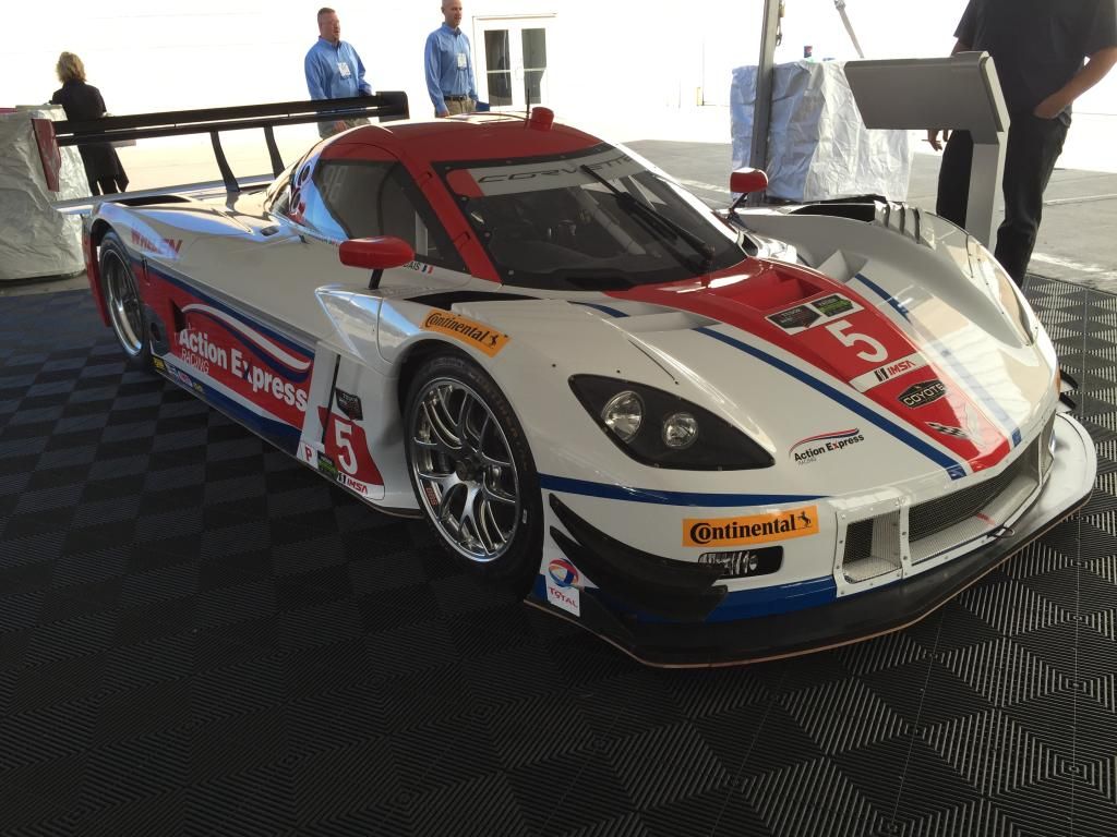
FYI our entire nose box that includes the radiator and splitter is removable and is considered the "crumple zone". The splitter is separately attached to the nose box, but it is rigid. You can kinda see in this pic how the splitter is attached. There is a framework UNDER the plywood as well that supports the skirt.
FYI our entire nose box that includes the radiator and splitter is removable and is considered the "crumple zone". The splitter is separately attached to the nose box, but it is rigid. You can kinda see in this pic how the splitter is attached. There is a framework UNDER the plywood as well that supports the skirt.
I was just thinking out loud, I have no relevance, and not referring to your car.
He will come up with something cool that I'm sure others will copy.
I was just thinking out loud, I have no relevance, and not referring to your car.
He will come up with something cool that I'm sure others will copy.
Sorry if it came across the wrong way. I was trying to say that you had the same idea that we have been using and it works very well. Great minds think alike.
I currently have a bit of a hybrid version.
My splitter tray is mounted to the chassis which tucks up inside the hood nose and the original CF FF5 splitter attaches to the hood.
Now that I have separated the nose from the hood itself I will convert to more in line with what the PDG car has as a set up.
We use plywood coated with resin. Pretty strong, very cheap.
Crash. no shame in plywood. Balsa wood core is still used in production cars, let alone one off race cars. I want to try to emulate my fabrication heros with fancy composites, but still keep the basic convenience of a tilt hood via the factory five design. And most importantly have a venturi under the nose to increase down force. Not sure if it can be done, but I will try.
Originally Posted by fastthings
I vote for solid as a rock and hope you don't hit something.
Gene, there is merit to the design where you make the splitter stand up to everything but a tire wall. A foam core with a composite skin will allow for both the freedom to have a complex three dimensional design splitter and under tray , but still be reasonably light and definitely something that can be reproduced so i can have a few spares.
Originally Posted by Fraser D
I currently have a bit of a hybrid version.
My splitter tray is mounted to the chassis which tucks up inside the hood nose and the original CF FF5 splitter attaches to the hood.
Now that I have separated the nose from the hood itself I will convert to more in line with what the PDG car has as a set up.
Dave I think this is the way to go.
Crash thanks for showing how PDG have the front under tray setup. I think what you guys have done is the right design. I might replace some of the solid struts with rod ends on aluminum struts, but in the big scheme of things thats just a nice to have and really does not impact the performance of the car. The only reason I would not use the solid flat bottom setup is the inability to contour the plywood to allow for a slot under the front of the car.
I think we all agree that a design that looks like this
is best to force air under the front of the car to increase air speed and generate down force.
Speaking with folks who have done testing of the GTM and cars with similar shape in the wind tunnel. Little changes like the amount of air going under the splitter/ out of the diffuser can make a massive difference in the total down force of the car.
IF i am lucky I will have a few designs to test on the track and maybe even in the wind tunnel.
John
XTF #2
build start date June 19 2023
GTM # 344
Build Start December 2010
First track day April 2013
Just keep in mind that just about every design you see out there is not usually a performance maximized design, but rather a performance maximized design given a particular set of rules. The splitter on the DP car is a great example.
Just keep in mind that just about every design you see out there is not usually a performance maximized design, but rather a performance maximized design given a particular set of rules. The splitter on the DP car is a great example.
Great point. I actually focus on what the rules prohibit. Usually prohibited thing works well
XTF #2
build start date June 19 2023
GTM # 344
Build Start December 2010
First track day April 2013
If you have no rules, I could see you designing a variable wing.
Any mounting, linkage would be easy for you. Sourcing the parts, for you, easy.
From there, tap it into a simple computer, speed inputs, brake inputs.
I like the C7R mod, that is going to be sick, I can't believe that hasn't been done yet.
In addition to the aero projects, I am tuning the suspension over the winter.
I found that more rear anti roll bar made the car handle better as I added more. I also have the rear shocks adjusted to full stiff both on compression and rebound.
The consensus is I need stiffer rear springs. The stock setup I'm running was intended for use on the street with street tires. It's actually pretty amazing that I was able to run the stock rear setup to this level of grip. Now it's holding me back.
So out come my dampers to be revalved for 20% stiffer springs. Maybe I'll install 4 way adjustable valves too as its an easy upgrade.
While working back there I think I an going to swap out my poly bushings for a spherical bearing kit. Seems like all the race teams go to spherical control arm bearings to get more accurate wheel control (camber,caster and toe) as well as more feel through the chassis. Of course this only matters at the limit on the track but I still don't have the same contact patch feel I learned to expect racing GP motorcycle. Maybe it's impossible to get that level of feel in a car but I figure stiffer is better.
Anybody have recommendations on,or experience with spherical bearings in a GTM or corvette?
With pfadt out of business LG motorsports seem to be the only game in town.
Thanks.
John
Last edited by kabacj; 11-19-2014 at 06:10 PM.
XTF #2
build start date June 19 2023
GTM # 344
Build Start December 2010
First track day April 2013
I'm real curios how the comp and rebound effect things. My guess is I think you will find the edge, with bigger sway bar, stiffer springs, which is good.
Is that how you ran your bike, stiff comp and stiff rebound in the rear? In the woods, I found it best with stiff comp and loose rebound at the rear.
We also just went stiffer on valving, springs, and rear bar. It was better.
We have purposely left the urethane bushings because we are not sure that the frame can handle the solid mounting and, well, we hit things during our long races.
We also just went stiffer on valving, springs, and rear bar. It was better.
We have purposely left the urethane bushings because we are not sure that the frame can handle the solid mounting and, well, we hit things during our long races.
Hey Mike
Good to know we are going in the same direction.
It does make sense that keeping the poly bushings would allow for some compliance to avoid bending or breaking parts if you rub or bump off of another car. Regarding the frame I am pretty sure the front is strong enough as I have beefed that up somewhat already when I added more structure to the cage and foot box. Of course when you guys are running 25 hours at a clip and you add lots of oscillation loads you will find the weak points.
I discussed adding the spherical bearings with Jim Schenk at SEMA. The 818r is running with spherical bearings using the same construction methods . Of course not the same frame. My gut says that after adding a few gussets for good measure, the fame will be fine. We will see however. I do not push any part of the frame as hard as you do in the 25 hour. I'll test it for a season. If I don't have problems maybe it will be an improvement you and Richard can add to the 25 hr car.
Originally Posted by fastthings
I'm real curios how the comp and rebound effect things. My guess is I think you will find the edge, with bigger sway bar, stiffer springs, which is good.
Is that how you ran your bike, stiff comp and stiff rebound in the rear? In the woods, I found it best with stiff comp and loose rebound at the rear.
I never liked an ultra stiff setup on the bike, but rather I like to be on the stiffer side just before the point where I would start to lose grip over rough or rippled pavement. I am pretty sure the setup does not translate between bikes and cars, but I am sure that when the suspension is too soft, I get too much weight transfer on both bike and car. On a bike you can compensate by shifting your body weight forward or back, not so much in the car.
I am very much a novice when setting up the car, but the GTM chassis is so stiff I can very easily feel one click of compression or rebound in the front or rear. That’s really cool. A stiff chassis makes it easier to tune the car since when you change a spring or damping setting you only have that change impacting the setup of the car. Where if you have a flexible car you are tuning to the car flex as well as the suspension compliance.
I think the art Morrison stuff is geared to their chassis instead of the c5 stuff we run. same idea however.
Last edited by kabacj; 11-21-2014 at 05:38 AM.
XTF #2
build start date June 19 2023
GTM # 344
Build Start December 2010
First track day April 2013
Here is a link to Pfadt Racing, It looks like they are back in business.
Hey Mike. Thanks. Looks like their web site still works but nobody is home. I gave them a call to see if they were in fact back in business and had inventory. Their number is out of service. I know they were at SEMA but I did not stop in to talk with them. I want to make sure they have what I need in stock before I order from them. Thanks for the heads up however.
John
XTF #2
build start date June 19 2023
GTM # 344
Build Start December 2010
First track day April 2013
There is a new number on the Pfadt web site, they changed ownership and are reorganizing.I left a message and got a reply from Steve at this number 951-493-7100 I am looking for a set of motor mounts and asked him about spherical bushings, he said he was going to check inventory and call me back.
There is a new number on the Pfadt web site, they changed ownership and are reorganizing.I left a message and got a reply from Steve at this number 951-493-7100 I am looking for a set of motor mounts and asked him about spherical bushings, he said he was going to check inventory and call me back.
Mike
Thanks Mike.
I was sorry to see that Pfadt went under as they sold very good products. Unfortunately sometimes it takes more then good products to succeed. But maybe now they resurface with some experience and a new plan. I hope it all works out. Let us know what you find out. I use their motor mounts and poly suspension and am very happy with no complaints.
John
XTF #2
build start date June 19 2023
GTM # 344
Build Start December 2010
First track day April 2013
I got a return call today and they have some inventory,I ordered the motor mounts and should get them in a few days. If you need anything call Mark @ 951-493-7108 he said that if they don't have it they should go back in production in a month or so.
I'm surprised that the ends of the A-arms haven't been cut off and replaced with some beautifully tigged 3/4" bore aluminum rod ends already It doesn't make replacement as easy as obtaining another C5 arm if you break one, but let me know if you want to fabricate arms and I can give you a Solidworks file with the dimensions. I made a set of lower arms on a strut car out of 1.25" x .110 mild steel, with 5/8" bore Summit brand rod ends. After 25,000 miles on the road, and a few hundred on the track, they are still doing fine. I even hit a curb once hard enough to bend the tubing - the rod end stayed intact.
Well Keith. Don't think I didnt consider modifying the A arms. Welding on the aluminum of the stock A arms would remove the heat treating. Maybe this would be fine but maybe not. A better route is to go with what you have done and fabricate arms. Nice job by the way. My dream solution would be to mill up billet arms like those used by the factory sponsored corvette race teams.
After all the dreaming I always come back to the same conclusion. Paying the price for a setup that easily fits into the stock c5 arms is actually the cheapest and by far the fastest most reliable solution.
Now don't get me wrong I would love to modify the stock units but I'm entering into uncharted territory there and for very little if any gain vs just retro fitting the stock setup with spherical bearings off the shelf.
I think in a future phase of the GTM development I will try my hand at fabrication like you did.
Right now I need to focus on getting ready for next year. I have a busy race schedule planned for next year starting in March. That's right around the corner! I am stressed already
Right now, I want to focus on the aero ideas you kindly outlined in detail. Rebuild everything that wears out. Setup the car for stiffer springs and a selection of anti roll bars. Tire pressure and temperature monitoring. And a few body mods that should make the car more slippery as well as closer to finished.
My goal is seat time. Lots of hours on the track will keep me busy maintaining the car. Since I am a one man team. Any place where I can use proven tested solutions will lower my workload next year.
I know you went through the exercise of measuring and building CAD drawings. Are you planning on building your own A arms for your GTM?
John
XTF #2
build start date June 19 2023
GTM # 344
Build Start December 2010
First track day April 2013
After spending several weekends putting natural gas heat in the garage then organizing the tools and supplies that have accumulated over the course of the build it was time to get some fabrication done.
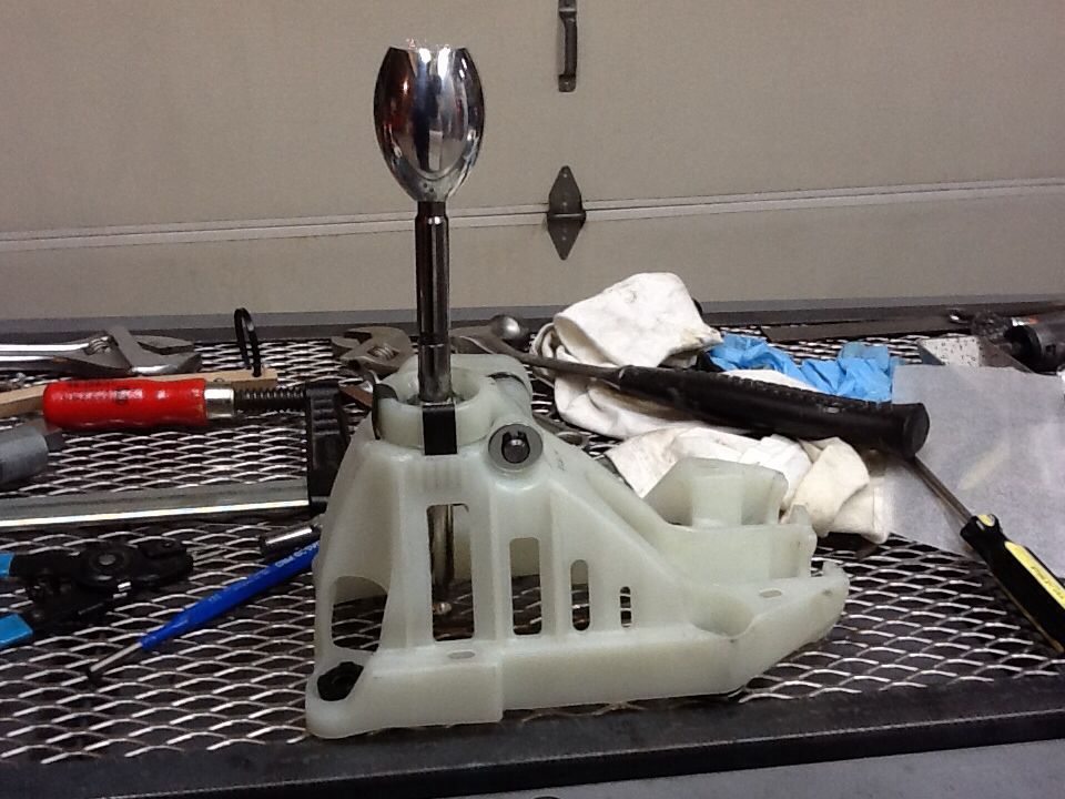
When the sequential transaxle arrives from Mendiola it comes with a shifter that you modify to your application.
I was so happy with the five speed mendiola transaxle I wanted to keep as many of the aspects of the setup as possible. One thing I tried to replicate was the shifter position and mounting location. If you are familiar with the shifter sold with the factory five kit the base has 4 mounting points one on each corner.
I needed to create a simple and quick solution to adapt the mendiola shifter. Turned out some angle iron got the job done. I have used this setup for the past year.
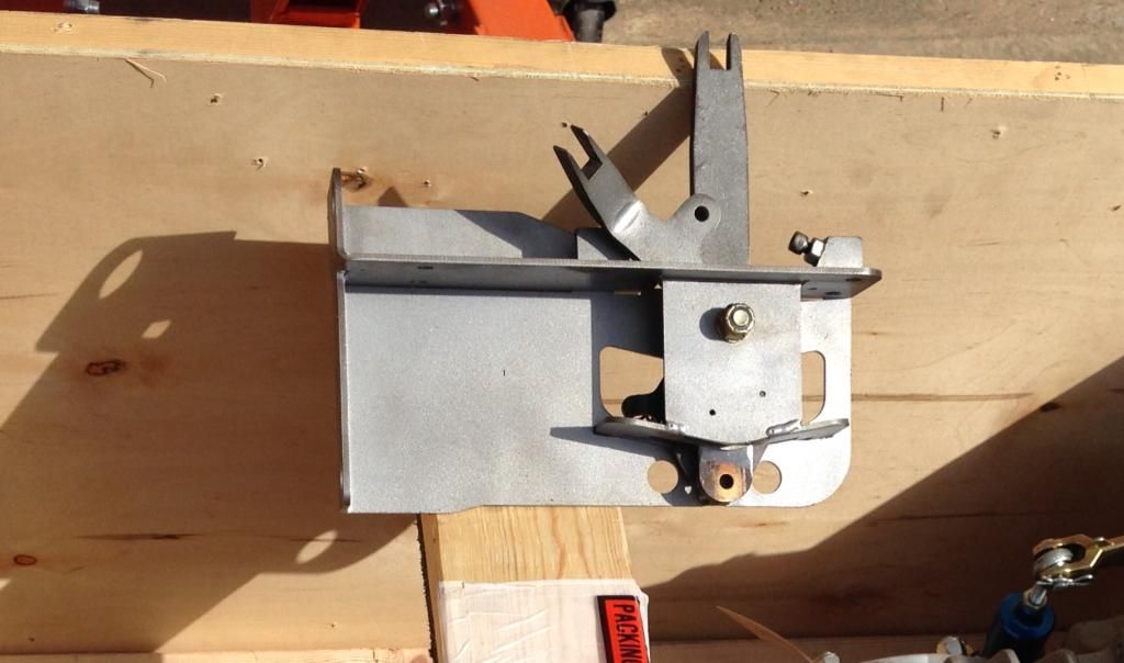
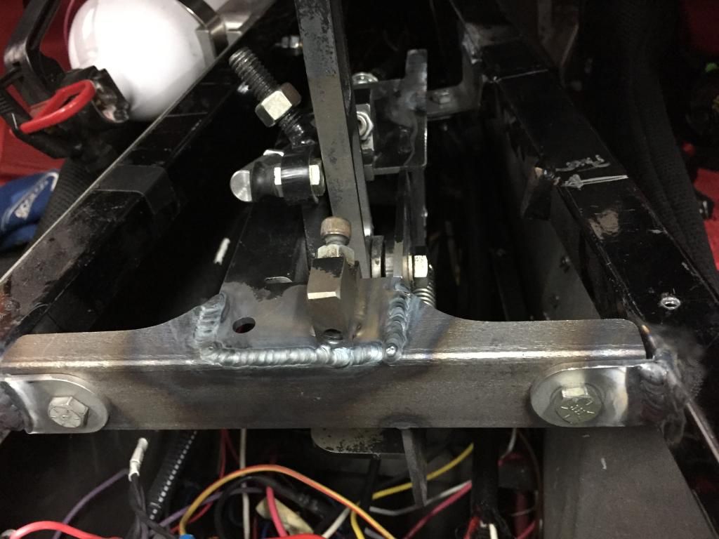
Now I want to move the shifter three inches forward. It will make for a slightly more comfortable driving position. I decided to mount the shifter to the tunnel frame instead of the Toyota shifter mount.
First I cut the metal that would span the tunnel. Then I cut and mounted two tabs to the shifter. The shifter has nuts welded on so assembly is a one wrench operation. I hate using two wrenches.
Finally I cut off the old mounts positioned the shifter and welded it in place.
With a tab in the back the shifter is amazingly rigid.
The next job is re routing the shifter cables.
John
XTF #2
build start date June 19 2023
GTM # 344
Build Start December 2010
First track day April 2013
Hey man, hows it goin. What do you use to cut that metal for those brackets, nice clean cuts.
I have never used a tig, are you using it for the steel also? I need to buy some tools!
Hey man, hows it goin. What do you use to cut that metal for those brackets, nice clean cuts.
I have never used a tig, are you using it for the steel also? I need to buy some tools!
Hi Gene.
I make most of my cuts with a 4x6 horizontal/ vertical band saw. The inside and outside cuts are cleaned up on a stationary sander or with a grinder.
Low tech and slow but it gets the job done.
Yep I tig everything. Tig gives you total control of the weld. Again it's slow, but the results are good. Yeah get some tools! You will want to modify even more than you already do!
John
XTF #2
build start date June 19 2023
GTM # 344
Build Start December 2010
First track day April 2013
Yes I have a metal brake, a lathe and a drill press. With exception to milled parts I can pretty much get what I need done.
Except for the TIG welder many of the tools were purchased used. Most times a well taken care of machine that is 60 years old is better then the new stuff built today at least for the money. When you get used tools you can afford a pro quality tool that is cheaper then a new hobbiest tool.
XTF #2
build start date June 19 2023
GTM # 344
Build Start December 2010
First track day April 2013
So two days of work and I am finally done reconfiguring my shifter and cables. This is exactly why I did not do this during the race season. I knew I would spend a couple of days making everything work they way I wanted.. and also I did not have the proper length cables or the time to get the job done right. I just made the cables I already had for the five speed Mendiola work.
In order to deal with the cables that were too short, I got a length of 1/4 28 threaded rod and a coupler and extended the shift rod. Of course this also required me to relocate the mount point for the cable on the transaxle.
I made the aluminum bracket as stiff as I could but it still flexed slightly when I shifted gears. Not ideal but It worked for several races and track days.
The proper way to mount the shift cable on the transaxle looks like this.
As you can see much shorter and as a result stiffer.
Now on the drivers side of the cable I needed to modify the sequential shifter that came with the transaxle so it fit in the GTM. My quick and dirty fix for that looked like this.
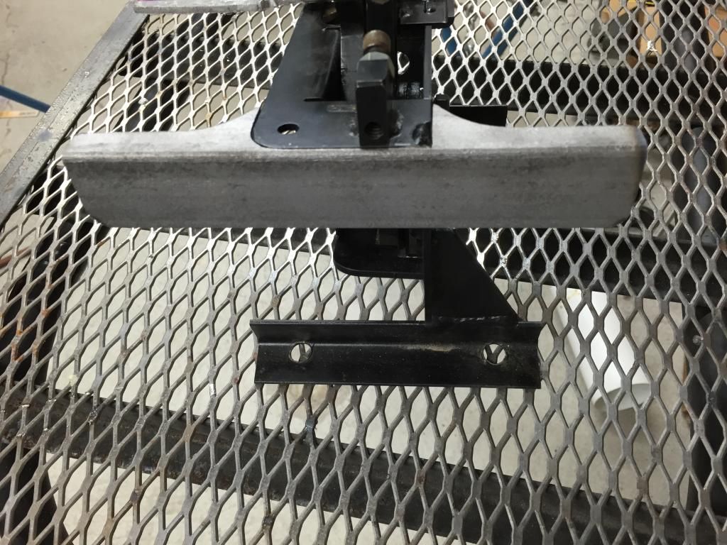
Now that I had the time I wanted to move the shifter more forward. (Impossible before as the cables were not long enough). The new position allowed me to mount the cables to the shift body in such a way as their was minimal flex.
The first go round I had the cables mounted to the shifter like this.
This allowed for the cables that were too short and the lack of space behind the shifter in the GTM center tunnel.
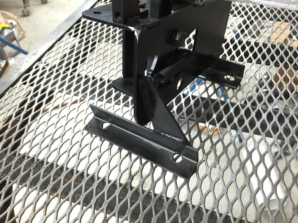
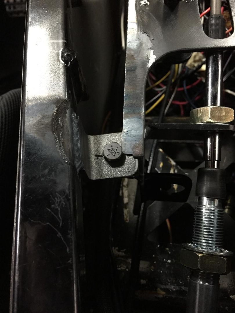
Now that I had both room behind the shifter in the tunnel and the proper length cables I moved the mount points back.
I also welded them together so they are much stiffer. They form a V shape which is far stiffer then a square welded to a flat surface and the lower bracket has a triangular brace attached to the shifter body again for stiffness.
The final result below.
I installed it and tested it out. The shifts are much more positive now. Lots of work for something that barely looks different, but it was worth it.
John
XTF #2
build start date June 19 2023
GTM # 344
Build Start December 2010
First track day April 2013
***SOLD!!! - NASA ST2 FFR#48 Gen3 Type65 Coupe R, Street legal.***
***SOLD!!! - NASA ST2 FFR#48 Challenge Car rolling chassis, Street legal.*** http://johngeorgeracing.com
***SOLD!!! - NASA ST2 FFR#48 Gen3 Type65 Coupe R, Street legal.***
***SOLD!!! - NASA ST2 FFR#48 Challenge Car rolling chassis, Street legal.*** http://johngeorgeracing.com
You need to come to my house, I'll take you to my track. This is in my back yard.
Gene this track is the perfect place to take your GTM. 1/2 mile long straight will have you up around 155 and all those twists and turns are going to be awesome. The GTM is a great car to cruise around in on the street but if you really want to see what it can do the track is the only place.
Can't wait to hear how you like it.
John
XTF #2
build start date June 19 2023
GTM # 344
Build Start December 2010
First track day April 2013
The past few weekends have been spent taking care of all the little things that don't stop me from racing, but I really wanted to get done. Things like pulling the unused AC lines and condenser out.
With those things done I started on the modifications to the under body panels. When I installed the dry sump I installed the remote oil filter in the cavity between the drivers side rear wheel and the engine. I left the underbody close out panel off so I could keep an eye on everything and check for leaks. Now that I am happy with the setup I wanted to replace the panel. Drilling out 25 rivets every time I needed to check in that area or change the oil filter was not going to happen.
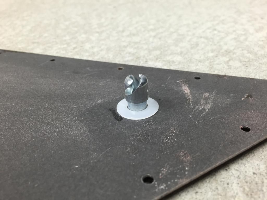
I did some searching and found this solution to add 1/4 turn fasteners.
This way 5 fasteners and the panel is off. Quick and easy. I forgot how cool these things are.
I welded in the plates then I needed to locate the holes on the panel.
Sure they sell tools for this , but I forgot to get one. I also figured I could do one better then the off the shelf tool. I lathed up this little tool out of a scrap dowel. Note the little green O ring I added.
It fits right into the plate and stays put while I install the panel and tap it with a hammer to make nice dimple in the aluminum sheet. The off the shelf tool would fall out working under the car. I drilled the holes and installed the buttons.
I like this solution so much I am installing the panels under the engine accessory drive, the panel I made for under the motor, and the diffuser with the same setup.
John
XTF #2
build start date June 19 2023
GTM # 344
Build Start December 2010
First track day April 2013
I have between working on small projects and learning how to vacuum form composite parts over the past few days. While doing that, I made a quick and easy upgrade everyone with a willwood brake / clutch pedal set can use.
Setting the brake proportion front to rear in requires moving the balance bar on the pedal assembly. Sure you can climb under the dash and make the adjustment, but doing that 10 times in a row as you slowly creep up on the ideal front to rear brake bias is a drag.
I personally only made a few adjustments and called it good. If I could adjust the bias on the fly I would use the bias as a way to setup the car for the conditions and grip each day.
Now with this setup from Wilwood 340-4990 Remote Brake Bias Adjuster Cable bias changes will be easy.
The install is quick even on a completed car.
You just simply thread the nut on the end of the adjuster on to the balance bar and snug up the lock nut.
Here is a shot of the cable that twists the balance bar.
and here is the knob that connects to the cable
All I need to do is mold my console cover to finish the install. Adding the knob under the dash or by the seat on the floor is also an option.
XTF #2
build start date June 19 2023
GTM # 344
Build Start December 2010
First track day April 2013


 Thanks:
  Likes:


 Reply With Quote


 It doesn't make replacement as easy as obtaining another C5 arm if you break one, but let me know if you want to fabricate arms and I can give you a Solidworks file with the dimensions. I made a set of lower arms on a strut car out of 1.25" x .110 mild steel, with 5/8" bore Summit brand rod ends. After 25,000 miles on the road, and a few hundred on the track, they are still doing fine. I even hit a curb once hard enough to bend the tubing - the rod end stayed intact.