Very Cool Parts

Visit our community sponsor

Thanks Thanks:  1
Likes Likes:  4
Page 11 of 23 FirstFirst ... 91011121321 ... LastLast
Results 401 to 440 of 908

Thread: GTM roll cage modifications and race car build log

  1. #401
    Member kabacj's Avatar
    Join Date
    Mar 2011
    Location
    Long Island
    Posts
    1,103
    Post Thanks / Like
    I had a feeling that I was subject to 3 different custom parts makers having all having tolerances that added up to a problem.

    It looks like that is exactly what happened.

    My main suspect was the clutch. However after walking through and measuring all of the parts with Kennedy Engineering on the phone. They are all with in spec. When I inspected the clutch it all seemed to be working properly. Each plate and steel surface had scuff marks from engagement. The clutch was clearly clamping when I pulled the transaxle out. My problem was that it was slipping with out fully engaging.

    I quickly realized that the problem was not with the clutch function, but rather the relative placement of the clutch between the motor and transaxle.

    When the transaxle was installed the throw out bearing was permanently pressing on the diaphragm spring . Even when I adjusted the clutch throw out fork to its max out position, It was still slipping the clutch.

    I did not realize this was the case when I installed the clutch and tested for some air gap between the throw out bearing and springs It sounds like there is air gap. You can hear a click as it he throw out bearing hits the diaphragm springs. But in fact the throw out bearing was backed into the bearing guide mounting bolts and I was hearing the click of free play in the assembly that moves the throw out bearing. You can not see the air gap between the clutch and throw out bearing on this transaxle as the bell housing does not have an access window.

    I did some careful measurement and confirmed the problem.


    There are a few ways I could think of fixing this.

    There is quite a bit of material on the back side of the area that the flywheel mounts to the crank shaft. That could be machined to bring the clutch assembly closer to the motor. Or the guide that the throw out bearing rides on in the transaxle could be moved back into bell housing OR I could simply make sure the throw out bearing goes back all the way back on its travel by trimming the bolts behind it.


    As I did not really need that much more clearance I opted for the easiest and fastest fix first.

    First I removed the lock washers. That got me a few tenths. Then I turned down the heads of button head allen bolts. I was able to make them thin, but I was concerned that I could easily strip out the allen head since I did not have a lot of material left. I decided that I would just turn down a normal hex head as that would be more sturdy and less likely to strip.


    With everything optimized and adjusted I was able to get a reasonable air gap
    If you don’t have one of these I suggest you get one.

    It’s a sealed usb camera with a LED lights. I hook this one to a piece of aluminum welding rod. And for 25 bucks I have a GREAT way to trouble shoot things without tearing them apart. For the transaxle I can fish the camera into the bell housing via the opening for the starter.

    I was able to inspect the clearances after some creative bending an twisting of the welding rod.

    Here is a picture of the back of the throw out bearing. I can confirm its bottoming on the bolt heads I turned down as it travels away from the clutch diaphragm spring.


    Here is a view of the air gap. Looks like enough. It looks bigger in the picture as we are super zoomed in.


    Now that its all sorted im optimizing a few of the cable routes and the position of the slave cylinder, and ill try to do a test run this week. Hopefully that solves my problem

    John
    XTF #2
    build start date June 19 2023

    GTM # 344
    Build Start December 2010
    First track day April 2013

  2. #402
    Senior Member Presto51's Avatar
    Join Date
    Feb 2011
    Location
    Catonsville, Maryland
    Posts
    578
    Post Thanks / Like
    If you don’t have one of these I suggest you get one.

    It’s a sealed usb camera with a LED lights. I hook this one to a piece of aluminum welding rod. And for 25 bucks I have a GREAT way to trouble shoot things without tearing them apart. For the transaxle I can fish the camera into the bell housing via the opening for the starter.


    Now we know where MacGyver retired too

    As always thanks for the great tip and for sharing

    BTW: You do know that I'm writing down all of your Tips, Tricks, and How To's. So don't be surprised when you see them pop up on a future build,

    Ron
    "May you be in heaven a full half hour before the Devil knows you're dead"

  3. #403
    Member kabacj's Avatar
    Join Date
    Mar 2011
    Location
    Long Island
    Posts
    1,103
    Post Thanks / Like
    Quote Originally Posted by Presto51 View Post
    [B][ So don't be surprised when you see them pop up on a future build,

    Ron


    Hey Ron,

    Glad if my "solutions" can be helpful in any way with your build.

    here is the camera I use.

    http://www.amazon.com/gp/product/B00...?ie=UTF8&psc=1

    Hooked to a laptop and using a bit of welding wire in order to direct the camera to its target, I think its better then a 250 dollar pro tool for ocasional use. The pro units have a flexi shaft that is harder to jamb into really tight spaces.

    As it did in this case. For 17 bucks I know what it looks like inside the bell housing at exactly the place I was interested in.

    Now lets just hope it works as well as it looks like its going to work.

    John
    XTF #2
    build start date June 19 2023

    GTM # 344
    Build Start December 2010
    First track day April 2013

  4. #404
    fasterer and furiouser longislandwrx's Avatar
    Join Date
    Aug 2012
    Location
    Long Island
    Posts
    2,540
    Post Thanks / Like
    Blog Entries
    6
    Quote Originally Posted by kabacj View Post
    You can not see the air gap between the clutch and throw out bearing on this transaxle as the bell housing does not have an access window.
    Is it possible to add one?

    Very impressive diagnostics. Especially on a few hours sleep. Hopefully the rain lets up Sunday and you can test the fix.
    A well stocked beverage fridge is the key to any successful project.

  5. #405
    Senior Member mikespms's Avatar
    Join Date
    Apr 2011
    Location
    North Miami,FL
    Posts
    145
    Post Thanks / Like
    http://www.mcmaster.com/#94414a583/=rviv86 Hi John, A couple of options for you,How about counter sinking the hole and using a flat head fastener or have you looked into a hydraulic throwout bearing and eliminating the slave cyl.
    Quote Originally Posted by kabacj View Post
    I had a feeling that I was subject to 3 different custom parts makers having all having tolerances that added up to a problem.

    It looks like that is exactly what happened.

    My main suspect was the clutch. However after walking through and measuring all of the parts with Kennedy Engineering on the phone. They are all with in spec. When I inspected the clutch it all seemed to be working properly. Each plate and steel surface had scuff marks from engagement. The clutch was clearly clamping when I pulled the transaxle out. My problem was that it was slipping with out fully engaging.

    I quickly realized that the problem was not with the clutch function, but rather the relative placement of the clutch between the motor and transaxle.

    When the transaxle was installed the throw out bearing was permanently pressing on the diaphragm spring . Even when I adjusted the clutch throw out fork to its max out position, It was still slipping the clutch.

    I did not realize this was the case when I installed the clutch and tested for some air gap between the throw out bearing and springs It sounds like there is air gap. You can hear a click as it he throw out bearing hits the diaphragm springs. But in fact the throw out bearing was backed into the bearing guide mounting bolts and I was hearing the click of free play in the assembly that moves the throw out bearing. You can not see the air gap between the clutch and throw out bearing on this transaxle as the bell housing does not have an access window.

    I did some careful measurement and confirmed the problem.


    There are a few ways I could think of fixing this.

    There is quite a bit of material on the back side of the area that the flywheel mounts to the crank shaft. That could be machined to bring the clutch assembly closer to the motor. Or the guide that the throw out bearing rides on in the transaxle could be moved back into bell housing OR I could simply make sure the throw out bearing goes back all the way back on its travel by trimming the bolts behind it.


    As I did not really need that much more clearance I opted for the easiest and fastest fix first.

    First I removed the lock washers. That got me a few tenths. Then I turned down the heads of button head allen bolts. I was able to make them thin, but I was concerned that I could easily strip out the allen head since I did not have a lot of material left. I decided that I would just turn down a normal hex head as that would be more sturdy and less likely to strip.


    With everything optimized and adjusted I was able to get a reasonable air gap
    If you don’t have one of these I suggest you get one.

    It’s a sealed usb camera with a LED lights. I hook this one to a piece of aluminum welding rod. And for 25 bucks I have a GREAT way to trouble shoot things without tearing them apart. For the transaxle I can fish the camera into the bell housing via the opening for the starter.

    I was able to inspect the clearances after some creative bending an twisting of the welding rod.

    Here is a picture of the back of the throw out bearing. I can confirm its bottoming on the bolt heads I turned down as it travels away from the clutch diaphragm spring.


    Here is a view of the air gap. Looks like enough. It looks bigger in the picture as we are super zoomed in.


    Now that its all sorted im optimizing a few of the cable routes and the position of the slave cylinder, and ill try to do a test run this week. Hopefully that solves my problem

    John

  6. #406
    Senior Member
    Join Date
    Feb 2011
    Location
    San Diego
    Posts
    1,963
    Post Thanks / Like
    Quote Originally Posted by mikespms View Post
    http://www.mcmaster.com/#94414a583/=rviv86 Hi John, A couple of options for you,How about counter sinking the hole and using a flat head fastener or have you looked into a hydraulic throwout bearing and eliminating the slave cyl.
    Hydraulic throwout will not fit. Wish it would. I've tried all of them starting with the Tilton units and ending with the McCleod units that are ultra short. There's just not enough room, especially with a multidisc.
    www.myraceshop.com

    GTM solution kits
    Corvette and Race parts

  7. #407
    Junior Member
    Join Date
    Nov 2012
    Posts
    7
    Post Thanks / Like
    Quote Originally Posted by mikespms View Post
    http://www.mcmaster.com/#94414a583/=rviv86 Hi John, A couple of options for you,How about counter sinking the hole and using a flat head fastener or have you looked into a hydraulic throwout bearing and eliminating the slave cyl.
    I'd keep an eye on the gap as the discs break in and wear; this would reduce the gap as the fingers would move outward with lining wear (and then there's a few thou of crank thrust). You should be able to feel some play by lifting on the arm connected to the slave--that's how I adjust ours. Can anything be gained by machining on the bellhousing or snout? Or perhaps a thin spacer between the bellhousing and engine. Enough to get clearance but not to lose pilot depth. You might have to add spacers to the rear mount also.

    Jimh

  8. #408
    Senior Member
    Join Date
    Feb 2011
    Location
    San Diego
    Posts
    1,963
    Post Thanks / Like
    Quote Originally Posted by tachman View Post
    I'd keep an eye on the gap as the discs break in and wear; this would reduce the gap as the fingers would move outward with lining wear (and then there's a few thou of crank thrust). You should be able to feel some play by lifting on the arm connected to the slave--that's how I adjust ours. Can anything be gained by machining on the bellhousing or snout? Or perhaps a thin spacer between the bellhousing and engine. Enough to get clearance but not to lose pilot depth. You might have to add spacers to the rear mount also.

    Jimh
    Just an FYI, that will also change starter pinion depth, which we seem to have at a minimum already.
    www.myraceshop.com

    GTM solution kits
    Corvette and Race parts

  9. #409
    Member kabacj's Avatar
    Join Date
    Mar 2011
    Location
    Long Island
    Posts
    1,103
    Post Thanks / Like
    Quote Originally Posted by mikespms View Post
    http://www.mcmaster.com/#94414a583/=rviv86 Hi John, A couple of options for you,How about counter sinking the hole and using a flat head fastener or have you looked into a hydraulic throwout bearing and eliminating the slave cyl.
    Hi Mike,

    Your suggestion of counter sinking the hole and using a tapered flat head fastener was plan B. The only down side to that solution that the holes in the throw out bearing carrier have some tollerance when bolted from above. The bearing guide can slide around and seat in the bell housing. If i were to counter sink the bolts my holes would need to be spot on as they now dictate the position of the bearing guide. I was also thinking that I could thin the rear section of the bearing guide to gain a few tenths.


    Originally Posted by kabacj

    You can not see the air gap between the clutch and throw out bearing on this transaxle as the bell housing does not have an access window.

    Originally Posted by longislandwrx
    Is it possible to add one?

    Yes I was thinking of cutting a hole and adding a brass plug. As suggested its possible to feel the air gap using the linkage, but its easier to tell how big the air gap is when you are looking at it.

    Quote Originally Posted by tachman View Post
    I'd keep an eye on the gap as the discs break in and wear; this would reduce the gap as the fingers would move outward with lining wear (and then there's a few thou of crank thrust). You should be able to feel some play by lifting on the arm connected to the slave--that's how I adjust ours. Can anything be gained by machining on the bellhousing or snout? Or perhaps a thin spacer between the bellhousing and engine. Enough to get clearance but not to lose pilot depth. You might have to add spacers to the rear mount also.

    Jimh
    Good point regarding adjusting for wear. Its possible to gain a little more clearance machining the bell housing so the throw out bearing guide sits slightly deeper. Hower we are limited by the linkage that operates the throw out bearing. The throw out bearing linkage also can be slightly modified.

    As you and crash point out shimming the bell housing will also require starter pinion adjustment. Thats actually not very difficult as the IMI 140 starter has a aluminum 1/2 inch thick machined part that mates the starter with the bell housing. I can remove that and turn it to the proper thickness.


    I could shim the bell housing using a strip of aluminum cut to match the outline of where the bellhousing meets the block. Machine down the starter mount by the same amount and then I would need to weld up and re drill the holes in the carrier that hangs the transaxle not a big deal.

    I think I could gain 1/4 inch of air gap that way.
    Lets hope it does not come to that.

    Thanks for all the suggestions guys.


    John
    XTF #2
    build start date June 19 2023

    GTM # 344
    Build Start December 2010
    First track day April 2013

  10. #410
    Member
    Join Date
    May 2011
    Posts
    77
    Post Thanks / Like
    I your spare time, might I suggest getting a plane ticket and coming to Ca. for a track day and drive my GTM. "For your own piece of mind. It will be worth it." eric burden

  11. #411
    Senior Member mikespms's Avatar
    Join Date
    Apr 2011
    Location
    North Miami,FL
    Posts
    145
    Post Thanks / Like
    Hi John,

    You should not have a problem as long the the thickness of the flange is not less that the taper on the head of the fastener and you use a counter sink to matches the head of the fastener usually 82deg. Make sure that when you counter sink you don't go to deep so that the threads don't bottom out before the taper.

  12. #412
    Member kabacj's Avatar
    Join Date
    Mar 2011
    Location
    Long Island
    Posts
    1,103
    Post Thanks / Like
    Quote Originally Posted by Cobra 61 View Post
    I your spare time, might I suggest getting a plane ticket and coming to Ca. for a track day and drive my GTM. "For your own piece of mind. It will be worth it." eric burden
    Hey Richard.

    I'm in California often. Thanks for the offer. Arrive and drive?!? I would not know what to do with myself. A marathon build session is part of my ritual before going to the track


    But I'm sure you are right. Because I don't have experience I'm only guessing. Experience is worth quite a bit and will ultimately save me lots of trial and error

    John
    XTF #2
    build start date June 19 2023

    GTM # 344
    Build Start December 2010
    First track day April 2013

  13. #413
    Member kabacj's Avatar
    Join Date
    Mar 2011
    Location
    Long Island
    Posts
    1,103
    Post Thanks / Like
    Thanks all for the suggestions.

    I was able to take the car out for a test drive over the weekend and WOW. I can't believe how good the sequential shifts.

    Of course I was not driving on the track, but it's amazing how smooth the shifts are. It's a dog box where fingers grab instantly instead of syncros slowly getting everything spinning the same speed. But it's not bone crushing. Pretty cool!

    I was instantly transported to my 125 gp bike racing days where with an ignition kill its possible to shift up and down at will. No clutch.

    Of course I'm not getting away with that above idle rpm and 30 mph but it's cool none the less.

    All I need to do is install a fire system, battery cut off, window nets, seat brace, rear tow hook, relocate the manual fire extinguisher and a few odds and ends and I'll be ready to get my NASA racing license on Friday.


    Plenty of time!

    John
    Last edited by kabacj; 05-13-2014 at 06:28 PM.
    XTF #2
    build start date June 19 2023

    GTM # 344
    Build Start December 2010
    First track day April 2013

  14. #414
    Member kabacj's Avatar
    Join Date
    Mar 2011
    Location
    Long Island
    Posts
    1,103
    Post Thanks / Like
    Good progress last night.

    The rear tow hook is installed.

    I welded a bit of 1/4 inch plate and a longitudinal brace to the rear sub frame. Then welded an aluminum coupling nut on to the subframe. This setup should be strong as well as removable. I was thinking that I can also attach a drag chute using the same nut for top speed events.

    Here is a view from the inside.


    John
    XTF #2
    build start date June 19 2023

    GTM # 344
    Build Start December 2010
    First track day April 2013

  15. #415
    Senior Member
    Join Date
    Apr 2011
    Posts
    641
    Post Thanks / Like
    Lookin good man, curious, where are you towing from the front. Iv'e been looking at that area trying to find a good location for a tow hook.

  16. #416
    Member kabacj's Avatar
    Join Date
    Mar 2011
    Location
    Long Island
    Posts
    1,103
    Post Thanks / Like
    Quote Originally Posted by fastthings View Post
    Lookin good man, curious, where are you towing from the front. Iv'e been looking at that area trying to find a good location for a tow hook.
    Hey Gene. I did some fab work to install the hook where I wanted it.


    You can check out more detail on how I did it on this thread.

    http://thefactoryfiveforum.com/showt...eferrerid=3030
    XTF #2
    build start date June 19 2023

    GTM # 344
    Build Start December 2010
    First track day April 2013

  17. #417
    Member kabacj's Avatar
    Join Date
    Mar 2011
    Location
    Long Island
    Posts
    1,103
    Post Thanks / Like
    You know how when you are under pressure somthing always goes wrong to compound the problems you need to deal with?

    This weekend the kids wanted a ride in the GTM. Because the clutch is very abrupt when it grabs I was trying to feather it but not revving like i would normally. With the almost 10 lb lighter flywheel it's easy to stall. So I stalled it and of course it has a tiny back fire out of one of the cylinders. The foam doesn't like that. The foam burns easily.


    Two day delivery to the rescue
    XTF #2
    build start date June 19 2023

    GTM # 344
    Build Start December 2010
    First track day April 2013

  18. #418
    Senior Member
    Join Date
    Apr 2011
    Posts
    641
    Post Thanks / Like
    You could just use some duct tape on that.

    Very cool on the front tow, I was thinking the same type of thing. I just wasn't sure about clearence with the hood open. I want to be done with mine so bad, but I just can't see finnishing this car without a place to tow it from.

    Thanks

  19. #419
    Member kabacj's Avatar
    Join Date
    Mar 2011
    Location
    Long Island
    Posts
    1,103
    Post Thanks / Like
    Quote Originally Posted by fastthings View Post
    You could just use some duct tape on that.

    Very cool on the front tow, I was thinking the same type of thing. I just wasn't sure about clearence with the hood open. I want to be done with mine so bad, but I just can't see finnishing this car without a place to tow it from.

    Thanks
    Well the good thing is these filters come with pre filters, so I could just put another layer of foam on top of what I have already. Luckily these filters are cheap. Regarding finishing the car, I use the tow hook all the time to pull it into the trailer. I think its a worth while addition.

    Regarding being done. You only start driving it, your never really done


    So after my mad rush to get everything installed in time. I did it. I got my NASA log book today.

    my log book.


    my 2014 tech sticker


    Boy was it a rainy day today.


    The rain was so heavy at times that they actually canceled the run group, because we couldnt see.

    Unfortunately not all of my electronics are rain proof. The isis is fine. But my rear view camera and rear view monitor might be kaput. I am drying them now, maybe they will work, but im not hopeful. Luckily both are cheap.

    The biggest downside will be the fact that I dont have a good rear view for tomorrow or Sunday. I purchased a bunch of blind spot mirrors to try to improve my analog viewing capability.

    Technology is fun, but good old fashioned mirrors are still better in many ways.
    XTF #2
    build start date June 19 2023

    GTM # 344
    Build Start December 2010
    First track day April 2013

  20. Likes RR46 liked this post
  21. #420
    Member
    Join Date
    Nov 2012
    Posts
    34
    Post Thanks / Like
    Looking awesome, standing still, or at speed! I'm still hoping to get to the track when you are there some time to say hi, how did the transaxle operate?
    2014-05-17.jpg

    2014-05-19.jpg

  22. #421
    Senior Member
    Join Date
    Feb 2011
    Location
    San Diego
    Posts
    1,963
    Post Thanks / Like
    Wow!

    That picture of the car at speed is one of the best ones I have seen in a long time. Saved it and it will be in my screen saver portfolio.
    www.myraceshop.com

    GTM solution kits
    Corvette and Race parts

  23. #422
    Member kabacj's Avatar
    Join Date
    Mar 2011
    Location
    Long Island
    Posts
    1,103
    Post Thanks / Like
    Quote Originally Posted by KeithBoden View Post
    Looking awesome, standing still, or at speed! I'm still hoping to get to the track when you are there some time to say hi, how did the transaxle
    That would be great Keith. I would love to see you at the track.

    You would not believe how many compliments and questions I get. It's non stop. My car is not even near finished and far from show quality. The whole bodywork and paint took me an afternoon.

    Your pictures make it look like a million bucks however. Thanks for posting.

    I think I am going to frame this one.


    The new transaxle is awesome. I'll have a track report out tomorow am with the whole story.

    Thanks again for the pics.

    John
    XTF #2
    build start date June 19 2023

    GTM # 344
    Build Start December 2010
    First track day April 2013

  24. #423
    Senior Member The Stig's Avatar
    Join Date
    Feb 2011
    Location
    Charlotte, NC
    Posts
    2,004
    Post Thanks / Like
    Quote Originally Posted by kabacj View Post

    Your pictures make it look like a million bucks however. Thanks for posting.

    I think I am going to frame this one.


    John
    Very cool picture!

    Mike
    The Stig

    Some say, that I only know two facts about ducks, (both being wrong); and that if I could be bothered, I could solve the "da Vinci Code" in 47 seconds...
    All I know is that I'm called "The Stig".
    GTM #0081

  25. #424
    Senior Member VD2021's Avatar
    Join Date
    Feb 2011
    Location
    Central, FL
    Posts
    958
    Post Thanks / Like
    Blog Entries
    2
    Quote Originally Posted by kabacj View Post
    That would be great Keith. I would love to see you at the track.

    You would not believe how many compliments and questions I get. It's non stop. My car is not even near finished and far from show quality. The whole bodywork and paint took me an afternoon.

    Your pictures make it look like a million bucks however. Thanks for posting.

    I think I am going to frame this one.


    The new transaxle is awesome. I'll have a track report out tomorow am with the whole story.

    Thanks again for the pics.

    John
    This is just an awesome photograph......
    R/s
    Vidal
    CURRENT STATUS: Interior Rework and Bodywork.
    GenII GTM #331. Delivered (23/9/10)
    BUILD LOG AND WEBSITE:
    http://gtmbuild.weebly.com/ .

  26. #425
    Member kabacj's Avatar
    Join Date
    Mar 2011
    Location
    Long Island
    Posts
    1,103
    Post Thanks / Like
    Quite an exciting 3 days at the track.

    The culmination of a build idea started in May 2 years ago at the start of this thread. My version of GTM chassis is approved for wheel to wheel racing.

    As is everything we do in life , my solution is heavily based on feedback and the experience of other people. Richard , Mike(crash) and Ted (quick racing products), Karen and Hank . As well as Joel who actually did the FEA to make sure this cage design will work. Thank you all for the help.

    The racing school started with an over cast day at around 9am. By 9.30 when we were ready to go out on the track the heavens opened. I have not done anything to keep out water on the GTM and lots of water comes in! The windows must be open and at some points the amount of rain coming in the window was as if I was racing in the rain on a motorcycle.

    Since I had brand new un scuffed Toyo 888s I had little traction. Well “little” is a bit of an understatement. I barely had any traction. After 3 sessions I still had some of the stickers left on the tires! It definitely made for a interesting drive.


    Of course I had planned to have a set of rain tires ready for my first track weekend just in case, but my rim order was delayed over 2 months for various reasons.

    I also had lots of new and un tested stuff on the car for this weekend.

    -deleted the cats (sounds GREAT)and probably a bit more power and no longer burns the CVs
    -added the aluminum rear sub frame / bumper and mendiola sequential with heavily modified shifter using my recycled cables from the SDR (too short so needed to be extended)
    -light weight flywheel and twin disk racing clutch
    -new tires R888 and increased the front tire size to 275 from 245 RA1 I was running last year.


    After my initial issues getting the clutch setup optimized, the sequential is unbelievable. Before I needed to plan my shifts bc I needed enough time to get the shift done. Now I can shift anywhere any time. I tried shifting mid corner. I drove it in pouring rain. Both were uneventful. Major improvement for the track.

    The combo of new tires and the sequential made the car much easier to drive when the track finally dried out. When you don’t need to worry about things, it frees up mental resources. Not worrying about shifting allowed me to run right in line with my average lap times from last year the first session out on the track in heavy traffic.

    The GTM feels better then it ever has! I am getting closer to a good racing setup.

    The only thing that was holding me back was a bit of rear end instability that has cropped up over the last few weekends. I had attributed the cause to way over used tires, but with 4 new tires I still have a serious wiggle when I pop off the throttle after a left hand turn. It almost feels like the passenger tire toes out or brakes when the car does its hard wiggle.

    As I went faster the problem started to show.

    Both rear wheels are rock solid. Bearings and all suspension points are very tight.
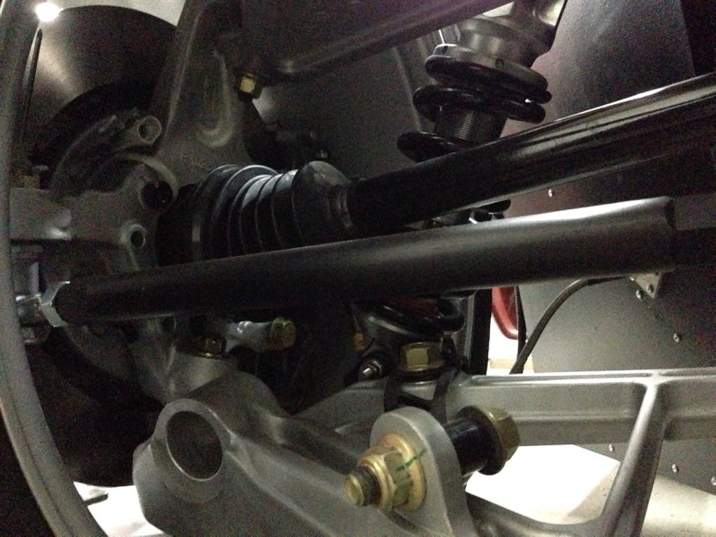
    I swapped the rear shocks left to right to make sure it was not a shock setting or broken valving. I checked every nut and bolt in the suspension. All are tight and have not moved since installation. I thought it could be one of the outer corvette CV joints going so I swapped in my new axles and outer CV joints and hubs.

    Because the new outer CVs and stub axles are wider then the corvette CVs. I needed to flip the shocks to make clearance. Both shocks are bolted in with nice ARP bolts.


    Unfortunately the ARP bolt and stainless fastener galled and the stainless nut cold welded it self on. I tried to break it off, but those stupid ARP fasteners are impossible to break.


    If I had more time I could have cut it off, but only had 35 min before the track closed for the night on Sunday. Just enough time to swap the axle and do a test lap if everything worked as it should. The passenger side is actually more likely to be the problem based on how the car acts but I was only able to replace the drivers side axle. Ill cut off the bolt and add a little anti seize to the replacement ARP bolts.

    Next step is a good alignment and corner weight. Unfortunately in order to see the instability problem I need to drive pretty aggressively. Not something I can do on the street. Id hate to go the next event without knowing the problem is fixed.

    Any ideas of how I can test the rear end for weird binding or deflection would be appreciated.

    John
    XTF #2
    build start date June 19 2023

    GTM # 344
    Build Start December 2010
    First track day April 2013

  27. #426
    Trick Tool Maker, Super Moderator Hankl's Avatar
    Join Date
    Feb 2011
    Location
    Northern CA
    Posts
    671
    Post Thanks / Like
    Blog Entries
    1
    John,

    The car has really come into its own! Glad I was able to help.

    Hank
    “If you didn’t have enough time to do it right the first time. How come you always have time to go back and do it again?” FFR1000186CP

    Understeer is when you hit the wall with the front of the car and oversteer is when you hit the wall with the rear of the car.
    Horsepower is how fast you hit the wall and torque is how far you take the wall with you.

  28. #427
    Senior Member
    Join Date
    Apr 2011
    Posts
    641
    Post Thanks / Like
    Put a camera at the wheel and watch it. I think you will see the toe changing. My buddy had a Vette that did that, bad. He said it was normal, I told him it was scary. Do a search for corvette rear bump steer.

  29. #428
    Member JCHRacer's Avatar
    Join Date
    Feb 2011
    Posts
    54
    Post Thanks / Like
    Great work John....congrats.

    I would suspect rear bump steer as well. Do you still have the soft Corvette bushings? Big power, soft bushings and bump steer are a bad combination. I use this to set the bump-steer on my cars:

    https://www.pegasusautoracing.com/pr...asp?RecID=2598

    With your McGiver skills, you can most likely rig up something cheaper but this concept is pretty good.
    Ciao,

    Joel

    Working ever so slowly on GTM #269, Twin Turbo SBC, Ricardo, Kit arrived April 5, 2009

    http://photobucket.com/JCHRacer_GTM_Build

  30. #429
    Senior Member
    Join Date
    Feb 2011
    Location
    San Diego
    Posts
    1,963
    Post Thanks / Like
    I would check everything on your rear toe links, including the mounts for any signs of distress. One of the very early things that we did on the FFR PDG GTM for racing was to strengthen the inner mounts with bracing and to go to real rod ends inner and outer. Deflection under moderate loading was the issue. In the second picture you can see the diagnol that we added that goes from the back of the toe link mount down to the frame on the left rear.

    DSCF3195.jpgDSCF3193 (2).jpg
    Last edited by crash; 05-21-2014 at 10:09 AM.
    www.myraceshop.com

    GTM solution kits
    Corvette and Race parts

  31. #430
    Member kabacj's Avatar
    Join Date
    Mar 2011
    Location
    Long Island
    Posts
    1,103
    Post Thanks / Like
    Quote Originally Posted by Hankl View Post
    John,

    The car has really come into its own! Glad I was able to help.

    Hank
    Thanks again Hank. Hopefully I can get out to Cali with the car and run a weekend with you guys.

    Quote Originally Posted by fastthings View Post
    Put a camera at the wheel and watch it. I think you will see the toe changing. My buddy had a Vette that did that, bad. He said it was normal, I told him it was scary. Do a search for corvette rear bump steer.
    Hey Gene. I agree bump steer could be a possibility. I did lots of research on the bump steer problem. I nearly eliminated bump steer on both the front and rear of the car by shimming the toe links to a location that was optimal. I will put a camera on the rear suspension/ wheel to confirm it's working as it should.


    Quote Originally Posted by JCHRacer View Post
    Great work John....congrats.

    I would suspect rear bump steer as well. Do you still have the soft Corvette bushings? Big power, soft bushings and bump steer are a bad combination. I use this to set the bump-steer on my cars:

    https://www.pegasusautoracing.com/pr...asp?RecID=2598

    With your McGiver skills, you can most likely rig up something cheaper but this concept is pretty good.
    Hi Joel. Yes I saw the same problem with the corvette bushings. I replaced them with pfadt poly bushings that are reported to control a slick shod 3300 lb c5. Could still be a problem but this setup is supposed to work. Thanks for the link. I rigged up a similar setup using a laser level with a beam splitter. I projected the beam on to a piece of paper 5 feet away from the wheel. As I ran the suspension through its travel I could mark the bump steer on the paper. I was able to nearly eliminate it front and rear.


    Quote Originally Posted by crash View Post
    I would check everything on your rear toe links, including the mounts for any signs of distress. One of the very early things that we did on the FFR PDG GTM for racing was to strengthen the inner mounts with bracing and to go to real rod ends inner and outer. Deflection under moderate loading was the issue. In the second picture you can see the diagnol that we added that goes from the back of the toe link mount down to the frame on the left rear.
    I also saw the rear links as a weak point. I upgraded to much heavier links with rod ends as well

    I checked the frame at the track. But I'll do a closer check this weekend.

    Here you can see the upgraded links adjusted down at the upright to eliminate bump steer.


    The weird thing is how this wiggle shows up. After a left hand turn and a full throttle 600 yard short shoot in a straight line. When I lift that's when it wiggles hard right. At worst I move over half a car width. I figure I keep the rear loaded through the corner and down the strait then when I lift it does it's weird thing.

    No weird sounds. AND the most maddening thing is it did not happen at all on Saturday. But just started on Sunday. It was happening November when I last drove it.


    Even though my stack DVL video/ data logger was literally filled with water after it dried out I kept working! Very surprising. I'll get a clip of what happens posed here this weekend.

    My hope is I find something that was binding the passenger side axle or the outer cv is sloppy.

    Thanks for the ideas guys. I'm sure we will figure it out.

    John
    XTF #2
    build start date June 19 2023

    GTM # 344
    Build Start December 2010
    First track day April 2013

  32. #431
    Senior Member
    Join Date
    Apr 2011
    Posts
    641
    Post Thanks / Like
    I'm sure you checked bump steer as well as possible. Put a camera on it, I think you will be supprized. You will be amazed at how much the suspension will flex under a load. The difference between full throtle/ compressing the rear, to off the throtle/ rebond= movement. It will only have to move slightly to give you a toe out, to toe in situation. There is a whole community of Vettes out there that would love to hear how you fix that, they think it's normal and live with it.

  33. #432
    Member JCHRacer's Avatar
    Join Date
    Feb 2011
    Posts
    54
    Post Thanks / Like
    Given that you have already addressed the rod end and soft bushing issues, If it turns out that deflection steer is still the issue, then stiffening up the rear steering link mounting points would be the first place to start.

    After that, if still having issues (or maybe in addition to) you can set up your bump steer to actually help you. Instead of shooting for minimizing bump steer at static ride height (you can’t get zero bump steer through full travel on most suspension layouts….including the GTM) you can actually set up preferential bump steer to help the problem. You can move the bump steer curve to give you some toe-in as the rear wheel goes into compression and slight toe-out as the rear wheel goes into extension. That way, you are essentially steering the rear wheels into the turn as the car rolls…..a very stable feeling. It will also add additional toe-in under power. A fine tuning effect to be sure but maybe worth a try as you get the car dialed in.
    Ciao,

    Joel

    Working ever so slowly on GTM #269, Twin Turbo SBC, Ricardo, Kit arrived April 5, 2009

    http://photobucket.com/JCHRacer_GTM_Build

  34. #433
    Senior Member
    Join Date
    Feb 2011
    Location
    San Diego
    Posts
    1,963
    Post Thanks / Like
    I do not think a CV will show itself in the manner that you describe. Maybe a bad wheel bearing, but not a CV. In my experience the CVs either work or explode if put into bind. Anything that is causing the car to "shift" a half car width is something major. We have had "wiggles" before when a rear suspension bolt was left loose, but that was about it as far as issues with rear "wiggle". I would double check everything. Also, just an observation, but your rear outer toe link is standing off the upright pretty far for a single shear setup. I hope you have, at least, an AN bolt in there, and an NAS would be advisable.

    Dynamic toe is something that is hard to tune on the GTM as the suspension is not really set up for it properly. No doubt it is what you want, and there are some reasons to change some of the pick up points on the GTM, (hint,hint)but it requires a lot of work to get there.
    www.myraceshop.com

    GTM solution kits
    Corvette and Race parts

  35. #434
    Member kabacj's Avatar
    Join Date
    Mar 2011
    Location
    Long Island
    Posts
    1,103
    Post Thanks / Like
    Quote Originally Posted by crash View Post
    I do not think a CV will show itself in the manner that you describe. Maybe a bad wheel bearing, but not a CV. In my experience the CVs either work or explode if put into bind. Anything that is causing the car to "shift" a half car width is something major. We have had "wiggles" before when a rear suspension bolt was left loose, but that was about it as far as issues with rear "wiggle". I would double check everything. Also, just an observation, but your rear outer toe link is standing off the upright pretty far for a single shear setup. I hope you have, at least, an AN bolt in there, and an NAS would be advisable.

    Dynamic toe is something that is hard to tune on the GTM as the suspension is not really set up for it properly. No doubt it is what you want, and there are some reasons to change some of the pick up points on the GTM, (hint,hint)but it requires a lot of work to get there.
    I agree with you the CV was a super long shot. I had checked everything else to the point where only the axle and CV were variables. (didn’t really consider the frame flexing)

    Since the last time I had this issue in November. I changed the transaxle. I swapped the shocks side to side this past weekend. I adjusted the damper and spring rates all with no real change in this behavior. I have 4 new tires. Everything in the rear drive line is new except the outer CVs that are known to be robust in the Corvette. I agree if they bind they explode, but I thought maybe the axle was not sliding in and out of the CVs and some how that was jacking up that corner and it would spring out after I let off the gas and I would get my wiggle.


    Yeah this is not a lose part wiggle . The first time it happened I thought I broke something. I actually have no problem driving something that is misbehaving as long as its predictable and semi controllable. This is a violent move but then its fine as if nothing happened….thats spooky.

    The fact pattern of the toe link flexing the frame changing the toe actually pretty closely matches the behavior I see. Many of my fast laps on Saturday I was held up behind people in the sections of the track where I really load up that corner of the car. Also on Saturday I was not as aggressively driving as I was on Sunday where I had worked out the right gears to be in and modified my timing accordingly. It still does not explain why its only shows this behavior after left turns and not right. Now that I think about it, maybe it happened to a lesser degree after one right turn, but again I need to check the data. Its possible I just load the left side up more on this track.

    This all makes me feel pretty good because stiffening up the toe link mounting point is a cheap and easy. I really tried to solve all the corvette related suspension flaws and it was pretty frustrating when I had this problem on the track but could not see any cause. Ill do some research to understand how I would change the geometry to provide dynamic toe.


    Quote Originally Posted by JCHRacer View Post
    Given that you have already addressed the rod end and soft bushing issues, If it turns out that deflection steer is still the issue, then stiffening up the rear steering link mounting points would be the first place to start.

    After that, if still having issues (or maybe in addition to) you can set up your bump steer to actually help you. Instead of shooting for minimizing bump steer at static ride height (you can’t get zero bump steer through full travel on most suspension layouts….including the GTM) you can actually set up preferential bump steer to help the problem. You can move the bump steer curve to give you some toe-in as the rear wheel goes into compression and slight toe-out as the rear wheel goes into extension. That way, you are essentially steering the rear wheels into the turn as the car rolls…..a very stable feeling. It will also add additional toe-in under power. A fine tuning effect to be sure but maybe worth a try as you get the car dialed in.
    Joel
    I agree the toe link mounting points are the most likely issue. You could never generate this much side load on the street and unless you are going reasonably fast on the track it actually is not a problem either. with the increased speed and new tires I am probably just pushing the stock frame too far.

    The dynamic bump steer is a great idea. I understand the concept, but ill need to learn how to modify the GTM to make it happen.


    Quote Originally Posted by fastthings View Post
    I'm sure you checked bump steer as well as possible. Put a camera on it, I think you will be supprized. You will be amazed at how much the suspension will flex under a load. The difference between full throtle/ compressing the rear, to off the throtle/ rebond= movement. It will only have to move slightly to give you a toe out, to toe in situation. There is a whole community of Vettes out there that would love to hear how you fix that, they think it's normal and live with it.
    Gene

    You are right. A camera will show exactly what’s going on. I’m going to work on how I can exaggerate the movements if things are flexing. 1/8 inch would be hard to see but if I say put a length of welding rod on the square tube like a pointer and had some visual reference I could see the toe link flex the frame.


    Thanks for the input guys. That really helps. At least now I have a good plan for solving the issue this weekend.

    I'll still post a video clip of the "wiggle" I think it's useful to see

    John
    XTF #2
    build start date June 19 2023

    GTM # 344
    Build Start December 2010
    First track day April 2013

  36. #435
    Member
    Join Date
    Feb 2011
    Location
    Sachse, TX
    Posts
    47
    Post Thanks / Like
    Quote Originally Posted by kabacj View Post
    Quite an exciting 3 days at the track.


    John
    In the picture above the corvette CV does not look right to me. I think it should be seated more. I don't think it should be out like it is. Maybe Crash could comment. I will look at mine and see.
    Last edited by GTMsomeday; 05-27-2014 at 04:41 PM.

  37. #436
    Junior Member
    Join Date
    Nov 2012
    Posts
    7
    Post Thanks / Like
    As Crash noted we have braced the rear toe link mounts on the PDG car. Before that we could apply force to a tire by sitting on the floor and using legs to steer the tire while someone watched the mount and link move.

    We are now faced with a similar problem where the car behaves perfectly with a 320 tire on a 12" rim but turns evil with a 355 tire on a 13+ rim that is widened only outside the hub. I'm considering that since the rear uprights are really front uprights with a 'solid' toe link you have to consider scrub radius like you would in the front (we tried front spacers for caliper clearance with evil results). With the widened wheel the tire center is moved more outward of the ball joint axis thus applying more force to the toe link and suspension bushings. In addition the increased track width makes any unequal accel or braking force between the rear tires have more leverage to alter the direction of travel. I want to try either eliminating the 1" spacers which will help the track width issue but really won't address the scrub radius issue--or just reverting to the 12" rims which could solve both issues.

    Just thought I'd throw this out there to see what you or the community might think.

    Jim H
    Team PDG

  38. #437
    Member kabacj's Avatar
    Join Date
    Mar 2011
    Location
    Long Island
    Posts
    1,103
    Post Thanks / Like
    Quote Originally Posted by GTMsomeday View Post
    In the picture above the corvette CV does not look right to me. I think it should be seated more. I don't think it should be out like it is. Maybe Crash could comment. I will look at mine and see.
    Very good catch. The corvette cv / axle is actually loose in this picture. I was in he process of taking the axle out and then stalled by the gauled arp nut and bolt on the lower shock mount.

    The cv should be closer to the upright when everything is installed.

    John
    XTF #2
    build start date June 19 2023

    GTM # 344
    Build Start December 2010
    First track day April 2013

  39. #438
    Member kabacj's Avatar
    Join Date
    Mar 2011
    Location
    Long Island
    Posts
    1,103
    Post Thanks / Like
    Quote Originally Posted by tachman View Post
    As Crash noted we have braced the rear toe link mounts on the PDG car. Before that we could apply force to a tire by sitting on the floor and using legs to steer the tire while someone watched the mount and link move.
    That's a great idea. This past weekend i spent some time bracing the right rear toe link mount. I can rig up something to apply side load to the rim and measure deflection on the toe link on the braced and un braced side. It would be great to have some measurement of what load is required to deflect the tire and rim.

    Quote Originally Posted by tachman View Post

    We are now faced with a similar problem where the car behaves perfectly with a 320 tire on a 12" rim but turns evil with a 355 tire on a 13+ rim that is widened only outside the hub. I'm considering that since the rear uprights are really front uprights with a 'solid' toe link you have to consider scrub radius like you would in the front (we tried front spacers for caliper clearance with evil results). With the widened wheel the tire center is moved more outward of the ball joint axis thus applying more force to the toe link and suspension bushings. In addition the increased track width makes any unequal accel or braking force between the rear tires have more leverage to alter the direction of travel. I want to try either eliminating the 1" spacers which will help the track width issue but really won't address the scrub radius issue--or just reverting to the 12" rims which could solve both issues.

    Just thought I'd throw this out there to see what you or the community might think.

    Jim H
    Team PDG
    I was wondering why you guys were not running wider rear tires! I have 335s on a 12 inch rim with 51mm offset for clearance of my stop tech big brake kit And 275s on the front. On my car I have the brake balance set so the rear end has a large influence on corner entry. I trail brake right to the apex and I can feel the rear tug on the car but it's nothing bad. That said braking balance is neutral /slightly front biased as the inside front locks before the rear on corner entry.

    This past weekend driving with unstuffed 888s in a downpour I was able to confirm the balance as lockup was as simple as braking at all. Hard acceleration was also neutral when I could get traction as the track changed from flooded with standing water to just wet.

    My theory is that if the GTM is well behaved with little traction in the rain, my instability might just be the rear toe link mount moving.
    XTF #2
    build start date June 19 2023

    GTM # 344
    Build Start December 2010
    First track day April 2013

  40. #439
    Senior Member Roger Reid's Avatar
    Join Date
    Feb 2011
    Location
    Caldwell (near Boise) Idaho
    Posts
    238
    Post Thanks / Like
    Quote Originally Posted by tachman View Post
    ...We are now faced with a similar problem where the car behaves perfectly with a 320 tire on a 12" rim but turns evil with a 355 tire on a 13+ rim that is widened only outside the hub. I'm considering that since the rear uprights are really front uprights with a 'solid' toe link you have to consider scrub radius like you would in the front (we tried front spacers for caliper clearance with evil results). With the widened wheel the tire center is moved more outward of the ball joint axis thus applying more force to the toe link and suspension bushings. In addition the increased track width makes any unequal accel or braking force between the rear tires have more leverage to alter the direction of travel. I want to try either eliminating the 1" spacers which will help the track width issue but really won't address the scrub radius issue--or just reverting to the 12" rims which could solve both issues...
    2 solutions to keep the wheel center from moving outward from the ball joint axis. Move upper and lower a arm pivot points outwards or longer custom A arms. Both of these would require a change in wheel offsets or less or no wheel spacer to keep the tire contact patch in the same position.
    Just an old man with a great hobby

  41. #440
    Junior Member
    Join Date
    Nov 2012
    Posts
    7
    Post Thanks / Like
    Quote Originally Posted by tachman View Post

    I want to try either eliminating the 1" spacers which will help the track width issue but really won't address the scrub radius issue--or just reverting to the 12" rims which could solve both issues.
    Oops, I realized I'd contradicted myself right after shutting down the computer to go unload the car--changing the spacer would in fact alter the scrub radius as it did in the front. Richard and I measured the track width with the widened wheel vs the 12" ones and found that we still needed some spacer for caliper clearance but going from the 1" to a 3/8" spacer got the track width much closer and hopefully the SR would get closer to normal.

    Admitting mistakes is essential to proper race team operation,
    Jim H
    Team PDG

Page 11 of 23 FirstFirst ... 91011121321 ... LastLast

Tags for this Thread

Posting Permissions

  • You may not post new threads
  • You may not post replies
  • You may not post attachments
  • You may not edit your posts
  •  

Stewart Transport

Visit our community sponsor