BluePrint Engines

Visit our community sponsor

Thanks Thanks:  2
Likes Likes:  1
Page 2 of 6 FirstFirst 1234 ... LastLast
Results 41 to 80 of 220

Thread: Mk4 #7750 Build Progress Update

  1. #41
    Senior Member edwardb's Avatar
    Join Date
    Feb 2011
    Location
    Lake Orion, Michigan
    Posts
    10,568
    Post Thanks / Like
    As updates go, this is pretty minor. But still a couple evenings of messing around and I'm happy with the results. I used Billet Specialties for the matching oval air cleaner and valve covers. Nice pieces, but I was concerned the provided 2 inch high air filter element was a little too small (restrictive) plus with the 302 sized block, have available height under the hood for something more. So, found a 3 inch K&N E-9201 that matched the oval dimensions exactly. But when I got it home, the inside dimension of the channels in the air cleaner housing top and bottom were too small. About 1/2 inch all around. The bottom is a cast piece. The top a machined piece. No other K&N options available, and didn't really want to look for something else. So tried to figure out a way to make this one work. Most of my tools are from my former days doing woodworking. I've found that a router with a good sharp carbide bit cuts aluminum pretty well if you have everything anchored down, take light cuts, and go slow. So made a template out of masonite, and with a bushing on the router, trimmed out the top and bottom of the air filter halves to fit the K&N filter. Turned out pretty good. The K&N filter fits like a glove.

    Air filter housing before:


    Air filter housing after:
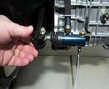


    Engine before:


    Engine after:


    As the pretty lame Wendy's commercials say, "Now that's better!"
    Build 1: Mk3 Roadster #5125. Sold 11/08/2014. Build 2: Mk4 Roadster #7750. Sold 04/10/2017. Build Thread
    Build 3: Mk4 Roadster 20th Anniversary #8674. Sold 09/07/2020. Build Thread and Video. Build 4: Gen 3 Type 65 Coupe #59. Gen 3 Coyote. Legal 03/04/2020. Build Thread and Video
    Build 5: 35 Hot Rod Truck #138. LS3 and 4L65E auto. Rcvd 01/05/2021. Legal 04/20/2023. Build Thread. Sold 11/9/2023.

  2. #42
    Senior Member edwardb's Avatar
    Join Date
    Feb 2011
    Location
    Lake Orion, Michigan
    Posts
    10,568
    Post Thanks / Like

    Instrument Panel Progress

    It’s been a while since my last update. Doing life with several breaks from the build. But still making progress. My main focus over the past weeks has been the instrument panel. It’s taken way longer than I originally expected. Many details, but finally have something to show. My design objectives for the dash were many:

    - Pretty traditional style with materials, gauges, switches, etc. I like the newer style modern dashes some guys do, but in the end my overall build is kind of a modern tribute.

    - Competition style layout. I just like it better. Started with a blank dash from FFR and did my own layout and cut-outs from there.

    - FFR Speedhut gauges, with the addition of an oil temp gauge. I had the oil and water temp gauges done in Fahrenheit. My brain just doesn’t wrap around Celcius.

    - Lucas switches for horn, wiper, fan and emergency. AC/Delco headlight switch with the FFR supplied knob. FFR ignition switch. Flush switches in the dash for seat heaters and fog/running lights. LED indicator lights for turn signals, high beam and cooling fan right in front where I can’t miss them.

    - Three dash supports. Narrow one at each end, with wider in the middle. Gives good strength, but still reasonably open for service. The end supports have down lights for the footwells. The center support has aux outlets for GPS, cell phone, etc.

    - I wanted to have a little more beef than the standard .040 dash. So I made a second .040 backer piece and laminated to the back of the FFR dash before doing all the cut-outs. It’s inside the 3/4 inch dash tube and stops short of the curve on the ends. I could have made a whole new dash out of thicker material, like many have done. But I didn’t have an easy way to do the bend along the bottom, which is critical to the look and strength of the final product. Just be aware that some of the normal pieces we use, e.g. the ignition switch and Lucas switches don’t like the thicker dash. Once you add the padding and vinyl on the front, you run out of mounting threads. You need to relieve the back of the dash to still only have the .040 of aluminum thickness where they mount. I planned ahead on the ignition switch and worked well. Didn’t plan so well on the Lucas switches so had to cut the reliefs after the dash was done and vinyl installed. Needless to say, that’s the hard way.

    - I wanted the dash mounts to be hidden, but still accessible should I ever need to remove it. So attached brackets to the backer piece using flat head machine screws captured between the lamination. Note I put the body on the chassis some weeks before (covered in a previous update) and did a bunch of fitting and mock-ups. So I was able to determine the exact position of the dash and the mounting brackets.

    - Alex’s glove box and vinyl covering. What I didn’t want though was the padded “plush” look. So instead of the foam padding, I applied a layer of marine vinyl (from Jo-Ann Fabrics) on the dash first, and then the vinyl covering from Alex. Gives a nice flat look with just a slight amount of cushion. The gauges and switches pull down into it slightly. I sanded a slight radius on the first coat of vinyl around the glove box opening. Then pulled the top layer around to the back. Nearly matches the glove box door radius. Everything looks really clean. I like the look.

    - I used DAP Landau Top & Trim High Heat Resistant Contact Cement for all the vinyl work. It’s supposed to be sprayed, which I initially thought about doing. But didn’t want to destroy a spray gun plus it’s really messy. So tried it with a small smooth foam roller, and worked great. I suspect I used way more material than you would if spraying, because even with a light touch the roller pushes the adhesive into the cloth liner on the back of the vinyl. So had to use a second coat there. But the least I could buy was a gallon, so had plenty. It flashes off very quickly and you can really keep moving with it. Other than the smell (!!!) it worked great. By all accounts I should have no issues with it delaminating due to heat.

    So here are pictures of the process and progress. First tweaked the competition layout so I had good sight lines on the gauges. Especially the tach which is partially hidden in my Mk3:


    Then laminated the backer onto the main dash piece. Used DAP Weldwood Gel Formula contact cement. Hadn't received the Landau yet. Will probably hold long term, but once all the gauges and switches are in there is also a mechanical hold between the two halves.


    Finished blank dash from back showing backer and mounting brackets.


    Dash after all cutouts completed. Mainly used a sabre saw with a fine tooth metal blade or a Dremel with a rotary bit and then cleaned up the edges with drum sanders in the drill press. Used step drills for the smaller stuff. Holes all sized to accept whatever went in each one plus the thickness of the vinyl pulled through to the back.


    Checking the fit of the dash to the chassis. All good!


    Front of dash after first layer of vinyl lamination.


    Back of dash after first layer of vinyl lamination.

    Build 1: Mk3 Roadster #5125. Sold 11/08/2014. Build 2: Mk4 Roadster #7750. Sold 04/10/2017. Build Thread
    Build 3: Mk4 Roadster 20th Anniversary #8674. Sold 09/07/2020. Build Thread and Video. Build 4: Gen 3 Type 65 Coupe #59. Gen 3 Coyote. Legal 03/04/2020. Build Thread and Video
    Build 5: 35 Hot Rod Truck #138. LS3 and 4L65E auto. Rcvd 01/05/2021. Legal 04/20/2023. Build Thread. Sold 11/9/2023.

  3. #43
    Senior Member edwardb's Avatar
    Join Date
    Feb 2011
    Location
    Lake Orion, Michigan
    Posts
    10,568
    Post Thanks / Like

    Instrument Panel Progress continued

    Final layer of vinyl in progress. I didn't apply the vinyl with contact cement exactly as pictured here, e.g. with the panel face up. I actually put the vinyl face down on the table behind, taping around the perimeter so it was perfectly flat. Then rolled on the contact cement, let it set up, and dropped the aluminum panel onto the vinyl. Pressed down as well as I could and pulled up onto the curved ends. Then carefully removed everything and placed it on the bench face up (as pictured) and very carefully rolled from the center out in all directions. I would not try to do it the other way around, e.g. move the vinyl into place vs. moving the instrument panel. Just too easy to let something stick too soon. There is no chance to reposition, and anything that touches even a little and try to lift will leave roughness under the vinyl that especially would show through since I'm not using the foam cushion.


    Finished, wrapped, and everything installed. Pretty stressful! I felt very lucky to get the vinyl installed without a bump or a blemish anywhere. It's perfect. Hopefully it stays that way.


    Backside isn’t quite so pretty.


    Checked needle and gauge illumination. Doesn’t show up very well, but everything is lit here. Flash washes it out. A little disappointed the clock hands aren’t lit, but knew that already from other comments.


    Quickly bolted it into the chassis tonight to get another look at everything. All good.


    Pretty much exact sight line from driver’s head sitting in seat. Can see all the important stuff.

    Last edited by edwardb; 01-12-2014 at 08:49 AM.
    Build 1: Mk3 Roadster #5125. Sold 11/08/2014. Build 2: Mk4 Roadster #7750. Sold 04/10/2017. Build Thread
    Build 3: Mk4 Roadster 20th Anniversary #8674. Sold 09/07/2020. Build Thread and Video. Build 4: Gen 3 Type 65 Coupe #59. Gen 3 Coyote. Legal 03/04/2020. Build Thread and Video
    Build 5: 35 Hot Rod Truck #138. LS3 and 4L65E auto. Rcvd 01/05/2021. Legal 04/20/2023. Build Thread. Sold 11/9/2023.

  4. #44
    Senior Member edwardb's Avatar
    Join Date
    Feb 2011
    Location
    Lake Orion, Michigan
    Posts
    10,568
    Post Thanks / Like
    All the wiring just jammed in there for now. Lots of work ahead to hook everything up and make it look a little better.


    I like it.


    Now to really get into the wiring.

    FYI, all the pictures in this build thread are taken with my Canon EOS Rebel and uploaded into Photobucket at full 12.2 MP resolution. So if you click the pictures in this thread it takes you to Photobucket. Then click the little magnifying class in the lower RH corner once, and then again for original size. You will get a very detailed picture you can scroll around in. Just promise you won't point out all the defects you can see then.
    Build 1: Mk3 Roadster #5125. Sold 11/08/2014. Build 2: Mk4 Roadster #7750. Sold 04/10/2017. Build Thread
    Build 3: Mk4 Roadster 20th Anniversary #8674. Sold 09/07/2020. Build Thread and Video. Build 4: Gen 3 Type 65 Coupe #59. Gen 3 Coyote. Legal 03/04/2020. Build Thread and Video
    Build 5: 35 Hot Rod Truck #138. LS3 and 4L65E auto. Rcvd 01/05/2021. Legal 04/20/2023. Build Thread. Sold 11/9/2023.

  5. #45
    Senior Member edwardb's Avatar
    Join Date
    Feb 2011
    Location
    Lake Orion, Michigan
    Posts
    10,568
    Post Thanks / Like
    Another few weeks and haven't had a lot of available time for the build, but made some important progress. I'm installing Fast Freddies power steering setup in the Mk4. Will use for the steering plus hydroboost on the brakes. The main work for the installation is mounting the pump. It's intended to be mounted at the center intersection of the front X brace. But this area is partially taken on my build by the Breeze front battery mount. The round tubes of the Mk4 make it a little interesting as well. Plus I wasn't a real fan of how it's shown to be installed, with the pump hookups on the front pointed down. Probably OK for PS only, but for my setup the high pressure line leaves the pump and first stop is the hydroboost unit. The low pressure line goes to the reservoir, so also a bit of a roundabout path from the front of the pump. At first I was going to make a new bracket. But after making a cardboard pattern, decided the supplied bracket just needed to be modified a bit. Only took two changes. First enlarged the semi-circle cutout so that it could be mounted from the other side. This put the hook-ups pointed up instead of down. Then cut a semi-circle channel about 1/8 inch deep between the upper mounting holes so that it could mount tighter against the round X tube. I don't know what aluminum Freddie made the bracket from, but it's way harder than the usual 6061. My wood cutting bandsaw didn't like it all. I used a metal cutting blade in a sabre saw, and using a lot of wax lubrication was able to final complete the cut out. The channel I made pretty much freehand with an air driven cut off-tool dragging the disc from one side to the other. Then cleaned up both using drum sanders. Turned out surprisingly well. Roughed it up and shot a coat of Duplicolor engine paint, and it was ready for mounting.

    This is the modified bracket waiting for the paint to dry. The bolt is just to hold it while painting and drying.


    Bracket mounted to the pump. This is the opposite side from how it's provided.


    Pump installed on chassis, from front. Note I just have room for the lower radiator hose bracket. Everything is well about the 4 inch tubes.


    Pump installed on chassis from engine compartment. Direction of hookups are nearly ideal for easy and direct runs. The pump is rock solid. I'm very pleased how well the round channel tightens against the round X tube.

    Build 1: Mk3 Roadster #5125. Sold 11/08/2014. Build 2: Mk4 Roadster #7750. Sold 04/10/2017. Build Thread
    Build 3: Mk4 Roadster 20th Anniversary #8674. Sold 09/07/2020. Build Thread and Video. Build 4: Gen 3 Type 65 Coupe #59. Gen 3 Coyote. Legal 03/04/2020. Build Thread and Video
    Build 5: 35 Hot Rod Truck #138. LS3 and 4L65E auto. Rcvd 01/05/2021. Legal 04/20/2023. Build Thread. Sold 11/9/2023.

  6. #46
    Senior Member edwardb's Avatar
    Join Date
    Feb 2011
    Location
    Lake Orion, Michigan
    Posts
    10,568
    Post Thanks / Like
    Also I've been working on the wiring. Not terribly exciting at this point. Basically I'm roughing everything in, then will start terminating and mounting to final lengths and locations. First is the primary 12V power. Have the front mounted battery, as mentioned, and putting a Ron Francis master cut-off in the cockpit below the dash. So the main 12V feed from the battery needs to go up to the cut-off, and then on the switched side will be the short run back to the starter and also power into the dash area and fuse box. I've put the battery ends on the wires, mounted the cut-off switch, and started working on the routing. I'll put everything in convoluted tubing and tie down once finalized. Also I started figuring out where things will be on the firewall, like the MSD ignition box. Just a few hours into this and way more to go. Next step will be to mount the breaker and relay for the power steering pump, and then start finalizing the primary power harness. Then will start behind the dash with the Ron Francis harness. But things are stopping for 8 days as I'm off on a business trip tomorrow.

    Firewall and cut-off switch location. Ignore the big coil of battery wire. Still have to cut to length. Just mocking up how the cables will route into the switch.


    Starting to route battery wires.


    Hope to have some serious wiring done for the next update.
    Build 1: Mk3 Roadster #5125. Sold 11/08/2014. Build 2: Mk4 Roadster #7750. Sold 04/10/2017. Build Thread
    Build 3: Mk4 Roadster 20th Anniversary #8674. Sold 09/07/2020. Build Thread and Video. Build 4: Gen 3 Type 65 Coupe #59. Gen 3 Coyote. Legal 03/04/2020. Build Thread and Video
    Build 5: 35 Hot Rod Truck #138. LS3 and 4L65E auto. Rcvd 01/05/2021. Legal 04/20/2023. Build Thread. Sold 11/9/2023.

  7. #47
    Senior Member edwardb's Avatar
    Join Date
    Feb 2011
    Location
    Lake Orion, Michigan
    Posts
    10,568
    Post Thanks / Like

    Electrical Wiring Update

    Finally have some more progress to report. Been working on the dash and main electrical harness. There's nothing wrong with the supplied Ron Francis wiring harness, and it can be used exactly as supplied with excellent results. But I also like to customize and change things. These are the modifications I'm doing:

    From rear harness: Removed fuel pump branch, shortened fuel tank sender. From main harness: Removed hot rod specific branch, removed inertia switch and tied grounds to use circuit for aux outlets, shortened headlight and ignition switch branches, cut off connectors and shortened alternator harness, shortened main power input branch, added taps for PS relay, headlight on chime, fog/running lights, trunk light, headlight relay, MSD ignition box. Added Weatherpack connectors and separate grounds for four corner lights, added Weatherpack connectors for cooling fan and license plate light. Added 100 amp fuse to alternator feed, used bus bar behind dash for power input and distribution.

    For the dash, I posted pictures before of the layout and gauges installed. Last night finished installing the Ron Francis dash harness. Put some power to it, and everything lights and blinks the way it should, so ready to go in the chassis.

    Ron Francis main wiring harness before:


    After:


    Bit of a haircut:


    Dash before:


    Dash after, ready to install:


    Not much build time this coming week because of work and travel, but will have the Thanksgiving week off, so hoping to get most of the wiring done and prep for engine installation.
    Build 1: Mk3 Roadster #5125. Sold 11/08/2014. Build 2: Mk4 Roadster #7750. Sold 04/10/2017. Build Thread
    Build 3: Mk4 Roadster 20th Anniversary #8674. Sold 09/07/2020. Build Thread and Video. Build 4: Gen 3 Type 65 Coupe #59. Gen 3 Coyote. Legal 03/04/2020. Build Thread and Video
    Build 5: 35 Hot Rod Truck #138. LS3 and 4L65E auto. Rcvd 01/05/2021. Legal 04/20/2023. Build Thread. Sold 11/9/2023.

  8. #48
    Senior Member CraigS's Avatar
    Join Date
    Feb 2011
    Location
    Blacksburg, Va
    Posts
    4,729
    Post Thanks / Like
    Your dash looks great! I am curious why two layers of vinyl?
    FFR MkII, 408W, Tremec TKO 500, 2015 IRS, DA QA1s, Forte front bar, APE hardtop.

  9. #49
    Senior Member edwardb's Avatar
    Join Date
    Feb 2011
    Location
    Lake Orion, Michigan
    Posts
    10,568
    Post Thanks / Like

    Wiring Update

    Had this past week off from work. Ate too much and watched too much football. But was still able to get a lot of quality build time. It’s amazing how the hours fly by. Looking back at the week, seems that I didn’t get as much done as I hoped. But things just take a long time (for me anyway) and even though I’m pretty comfortable with electrical wiring, I’m going really slow taking a lot of notes and testing repeatedly to make sure everything works as expected.

    I’m using a standard FFR supplied Ron Francis harness. In my last update I outlined several of the changes and additions I’m making. I have a front mounted battery (Breeze) and a master cut-off switch centered under the dash. So power comes from the battery to the cut-off switch, and then back to the starter plus a branch to the fuse panel. I brought the main power into the dash area using a Blue Sea Systems bus bar. These parts are intended for marine use, so probably a little overkill. But nice parts. The bus bar has the main power in, two main power feeds to the harness, and the alternator. Then added taps for the headlight module and fog/running lights through circuit breakers. I added a mega fuse for the alternator feed, also a Blue Sea Systems part. I didn’t plan to use a starter solenoid with the mini-starter. Don’t have one on my Mk3, and so far so good. But after reading some concerns about running the current through the ignition switch, added a 60 amp relay to the blue solenoid feed wire. An easy add.

    I now have all the branches mounted (main, front, back, dash, etc.). Brake light, clutch safety and main ground wires mounted. Have the MSD ignition box mounted on the firewall. I found several recommendations from MSD and others that an MSD filter capacitor on the MSD box provides good protection and could prevent failures due to voltage spikes or whatever. So got one and it’s mounted right behind the MSD box on the firewall brace. Both the +12V and ground for the MSD box go through the filter capacitor. I made a panel to mount the American Autowire headlight module and two circuit breakers. On the dash center brace panel I mounted two more relays (fog/running lights, headlight on chime), two switches (PS cut-off and ignition immobilizer), and two 12V aux outlets. I have a smaller dash brace panel at each end of the dash. Each has an LED downlight for the footwells that will be attached to the courtesy light circuit. The main work left is to complete all the point-to-point wiring. The dash is done and ready to plug in.

    All the wiring is being done with a decent crimper, a light touch of solder on the crimp (Let's not debate that please. I have a solder station and am pretty experienced with it from my R/C days...), and adhesive shrink sleeving. Should be durable and reliable.

    The last thing I did tonight was lay out the wiring for the Freddie’s PS setup. Finally decided where I’m going to mount the breaker and relay. With those in place I can now finish up the main power wiring in the engine compartment. I'm going to wait until the engine is installed to bring the rest of the wires into the engine compartment. Like hookups for the various senders, choke, fan, etc. That way they're in exactly the right place through the firewall and as hidden as possible.

    Snapped a few pictures. Looks way worse than it is (really). In fact, looking at it this way doesn’t seem that I accomplished too much.

    Bus bar and mega fuse before hooking anything up. Each has an included cover, visible in the next pictures.


    Lots of loose wires.


    Build 1: Mk3 Roadster #5125. Sold 11/08/2014. Build 2: Mk4 Roadster #7750. Sold 04/10/2017. Build Thread
    Build 3: Mk4 Roadster 20th Anniversary #8674. Sold 09/07/2020. Build Thread and Video. Build 4: Gen 3 Type 65 Coupe #59. Gen 3 Coyote. Legal 03/04/2020. Build Thread and Video
    Build 5: 35 Hot Rod Truck #138. LS3 and 4L65E auto. Rcvd 01/05/2021. Legal 04/20/2023. Build Thread. Sold 11/9/2023.

  10. #50
    Senior Member edwardb's Avatar
    Join Date
    Feb 2011
    Location
    Lake Orion, Michigan
    Posts
    10,568
    Post Thanks / Like

    Another Wiring Update

    Had a good week and weekend making progress with the wiring. Finished all the wiring behind the dash with the exception of the circuits going into the engine compartment (gauge senders, choke, alternator, etc.). I'm going to save those until the engine is installed to get the exact location(s). Called it good and mounted the instrument panel for (hopefully) the last time. Plugged everything together, and tested all the circuits. Everything works! All the lights, turn signals, fan, horn, needles swing, headlight high and low beams, etc. Managed to pop one fuse in the panel when I touched a couple alligator clips together while testing. Actually I was just testing to see if the fuses worked like they're supposed to. (That's my story and I'm sticking to it...)

    Hard to make the wiring look pretty. But everything's neatly laid out, tied down, etc. The dash is 100% connectors so can be unplugged and removed if needed (not that I really want to do that). Possible service items like the three relays I added, the alternator megafuse, MSD box, and American Autowire headlight module are all also on connectors and accessible from under the dash.

    You may notice I threw a piece of large shrink sleeve around the ignition switch. I have three braces on the dash -- wide one in the middle and a narrow one at each end -- but the underneath is open in the area of the ignition switch. With the location near the bottom of the dash (pretty normal) there's full battery power exposed, plus it's an easy mark if someone wanted to hot wire. The sleeving can be easily removed if necessary for service.

    Some work remaining to wrap up the main power wiring in the engine compartment. Then will mate the engine / trans and get it installed. Now that will be progress. Here are some pictures:

    Everything connected. Compare these pictures to the ones in my last update.


    Dash installation complete:


    Before: (Some weeks ago with the harness just laying in place and instrument panel temporarily hung)


    After:

    Last edited by edwardb; 01-13-2014 at 12:56 PM.
    Build 1: Mk3 Roadster #5125. Sold 11/08/2014. Build 2: Mk4 Roadster #7750. Sold 04/10/2017. Build Thread
    Build 3: Mk4 Roadster 20th Anniversary #8674. Sold 09/07/2020. Build Thread and Video. Build 4: Gen 3 Type 65 Coupe #59. Gen 3 Coyote. Legal 03/04/2020. Build Thread and Video
    Build 5: 35 Hot Rod Truck #138. LS3 and 4L65E auto. Rcvd 01/05/2021. Legal 04/20/2023. Build Thread. Sold 11/9/2023.

  11. #51
    Senior Member edwardb's Avatar
    Join Date
    Feb 2011
    Location
    Lake Orion, Michigan
    Posts
    10,568
    Post Thanks / Like

    Power steering and brakes completed

    Having a pretty productive Christmas holiday break. The Fast Freddies EHPS is wired, plumbed, filled and running. As outlined in earlier posts, using the pump for power steering and hydroboost power brakes. After an initial issue with a defective fitting, got that replaced and I’m running with no leaks. I used Honda branded PS fluid from a local Honda dealer. The pump isn’t silent, that’s for sure, but I’m not unhappy with the sound level. The cooling fan in the shroud is louder. With the engine running, don’t expect it will be noticeable. Here are some pictures:

    Wired the breaker and relay per Freddie’s instructions. Played around with some other locations. But decided the recommended location was the simplest and works fine. The system gets a direct battery feed, with a trigger wire from the ignition switch.


    06 AN braided stainless Teflon lined hose hookups at the hydroboost unit. Used the Hydrotech Brake HBS9101 adapter instead of the return line nipple, so an AN fitting there as well.


    Hook-ups and reservoir from the engine compartment.


    Hose hookups at the pump. This is the location described in an earlier posts allowing for the round tubes of the Mk4 and the Breeze front battery box. Note that with the flipped and reversed pump location, the hose connections are direct and clean.


    Also as noted earlier, I mounted a small cooler on the back of the radiator shroud. Here it is all hooked up. Maybe not needed, but cheap insurance and easy to install now. Not so much later.

    Build 1: Mk3 Roadster #5125. Sold 11/08/2014. Build 2: Mk4 Roadster #7750. Sold 04/10/2017. Build Thread
    Build 3: Mk4 Roadster 20th Anniversary #8674. Sold 09/07/2020. Build Thread and Video. Build 4: Gen 3 Type 65 Coupe #59. Gen 3 Coyote. Legal 03/04/2020. Build Thread and Video
    Build 5: 35 Hot Rod Truck #138. LS3 and 4L65E auto. Rcvd 01/05/2021. Legal 04/20/2023. Build Thread. Sold 11/9/2023.

  12. #52
    Senior Member edwardb's Avatar
    Join Date
    Feb 2011
    Location
    Lake Orion, Michigan
    Posts
    10,568
    Post Thanks / Like

    Electrical wiring nearly completed

    Also able to finish the bulk of the electrical wiring. The only thing left are the wires to the engine (sensors, choke, ignition, etc.) that I’ll finalize after the engine is installed. Everything is checked out and working perfectly. I clipped in all the lights and cycled through every possible combination. All is good! So far, I’m really happy with how the American Autowire headlight module it working.

    It was fun removing the 12V power supply I've been using during the wiring stage and finally running everything off the battery. It's now completely standalone. I tried to convince my wife it was now living and breathing. But she always tries to convince me it's just an inanimate object. Imagine that!

    The main work completed since the last update was the main power wiring from the battery to the master cut-off switch and back to the starter. Also finished the Weather Pack connectors on all four corners, installed the high dollar Harbor Freight horns, and wired the cooling fan. Note that I added chassis grounds to each corner. I took the RF provided ground wire to the chassis, and then branched to the connectors and in turn the lights. These additional grounds plus the couple that I added behind the dash provide a lot of redundancy. Here are some pictures.

    PS front corner lights. The added ground point can be seen. The lower connector is for the Tangent running lights in the oil cooler opening.


    DS front corner lights and horns.


    DS rear corner. The added gound is underneath.


    PS rear corner. These aren’t that exciting, but there you go.


    Battery connections with the Breeze front battery mount. The empty ground lug is for one of the engine ground wires. I’ll finalize that once the engine is installed.


    Main battery power along the PS 4 inch tube.

    Last edited by edwardb; 01-13-2014 at 01:00 PM.
    Build 1: Mk3 Roadster #5125. Sold 11/08/2014. Build 2: Mk4 Roadster #7750. Sold 04/10/2017. Build Thread
    Build 3: Mk4 Roadster 20th Anniversary #8674. Sold 09/07/2020. Build Thread and Video. Build 4: Gen 3 Type 65 Coupe #59. Gen 3 Coyote. Legal 03/04/2020. Build Thread and Video
    Build 5: 35 Hot Rod Truck #138. LS3 and 4L65E auto. Rcvd 01/05/2021. Legal 04/20/2023. Build Thread. Sold 11/9/2023.

  13. #53
    Senior Member edwardb's Avatar
    Join Date
    Feb 2011
    Location
    Lake Orion, Michigan
    Posts
    10,568
    Post Thanks / Like
    Main battery power connections to the master switch.


    Master switch under the dash.


    Tomorrow I will start preparing for the engine for installation. Can’t wait to get that thing off the stand and into the car. Could be interesting if we get as much snow as is being predicted. Would be too bad if I couldn't get back to work on Monday.
    Build 1: Mk3 Roadster #5125. Sold 11/08/2014. Build 2: Mk4 Roadster #7750. Sold 04/10/2017. Build Thread
    Build 3: Mk4 Roadster 20th Anniversary #8674. Sold 09/07/2020. Build Thread and Video. Build 4: Gen 3 Type 65 Coupe #59. Gen 3 Coyote. Legal 03/04/2020. Build Thread and Video
    Build 5: 35 Hot Rod Truck #138. LS3 and 4L65E auto. Rcvd 01/05/2021. Legal 04/20/2023. Build Thread. Sold 11/9/2023.

  14. #54
    Senior Member edwardb's Avatar
    Join Date
    Feb 2011
    Location
    Lake Orion, Michigan
    Posts
    10,568
    Post Thanks / Like

    Engine and transmission final assembly update

    Made some good progress getting the engine, transmission, and related parts together. First order of business was to install the motor mounts. Right away discovered a problem. I have the pretty typical Energy Suspension polyurethane engine and transmission mounts. Seems that my DART SHP block has an extra web on each motor mount boss that directly interferes with the corner of the motor mounts. I couldn’t imagine cutting any metal on my DART block. A quick search found this was a pretty common problem, and the recommended fix (including directly from my engine builder) is just to notch out the Energy Suspension motor mounts to clear the block. I used some marking grease left over from my differential gear change (I knew it had to be good for something) to get the exact spots. A little trial and error with an air cut-off tool, and I had the clearance necessary and they mount up just fine. Then off with the carb, on with the lifting plate, out with the shop crane and the engine was freed from the engine stand for hopefully the last time. I have a pretty crude homemade wood stand to set the engine on the mounts and access the back. Not pretty but it works. Better than a tire.

    First step was to install the Ford Racing pilot bearing. Popped it into the freezer for a couple hours, put a little wipe of WD-40 in the bore, and a few good whacks with a large socket and a dead blow hammer and it was home in the back of the SCAT forged crank. Then on the with QuickTime block plate. Tight fit over the dowels but perfect alignment with all the bolt holes including the starter. That has been a problem with QuickTime in the past. Now apparently finally fixed. Then installed the Ford Racing billet steel flywheel. Used ARP bolts, a little ARP lube on the heads and Loctite 567 Teflon Thread Sealant on the threads. Torqued to the ARP recommended 75 foot pounds. I had already installed the clutch dowel pins. (Interesting story there. Apparently it's not a good idea to take the dowel pins out of the freezer and pound them into the flywheel on the basement floor at 7:00 AM in the morning like I did several weeks ago. I'm told this makes a terrible racket and tends to wake up others in the house. Who knew?)

    Although not mandatory, it’s usually recommended to check the bell housing for proper alignment with the crankshaft. The instructions are provided from QuickTime, and are pretty standard for all. First bolted on the bell housing with no clutch, clutch fork, or pivot ball. Then mounted a dial indicator on the flywheel, and adjust the plunger to contact the circumference of the transmission bore of the housing. Zero’d the indicator, and then rotated the crank stopping every 90 degrees are so to check the reading. Maximum allowable off center is .005. Mine was a little over .001 at the worst, and near zero much of the time around. Pretty good and nothing to be done here.

    Then onto the McLeod Super StreetPro clutch. Cleaned the flywheel and pressure plate with carb cleaner, used the provided alignment tool to locate the clutch disk, and mounted the pressure plate. Used blue Loctite and torqued to the recommended 20 foot pounds.

    Next was to set the adjustable clutch fork pivot ball in the bell housing. I kind of guessed at the first setting and trial fit the bell housing with the clutch fork and throw-out bearing in place. A few more off and on adjustments and found the spot where the throw-out bearing was slightly away from the pressure plate and the fork straight or slightly forward in the bell housing opening. Used blue Loctite and a good grunt on the lock nut to lock in this position for the pivot ball. Then clipped in the clutch fork with throw-out bearing and bolted up the bell housing for hopefully the last time.

    I was going to stop there, but since all was going well decided to see if I could persuade the TKO600 into place. The thing is not light (and my back is weak) but I didn’t want to get out the shop crane again. So kind of jury rigged around with two floor jacks and was able to get it lined up and finally in. The fit between the TKO and the bell housing hole is a pretty tight interference fit. No way it's going to just push in. So very carefully did use the mounting bolts to draw it into place (even though instructions say not to do this) but I was super careful to make sure everything was kept in perfect alignment the whole time and going in properly including the input shaft splines and pilot shaft. Engine turns freely and the output shaft turns when it's in gear. So all is good.

    Last step was to quickly bolt on the Forte hydraulic clutch pieces. I have some work to do here to get the alignment a little better than it is. Found some threads that address this, so think I know what to do. Once that’s done, I’m planning to plumb the line from the clutch master cylinder and confirm the clutch is working properly before installing into the car. Back to work tomorrow and a more normal schedule, so could be a week or two, but hopefully will be ready to drop this all into the chassis soon. Pictures taken along the way:

    Block plate installed.


    Pilot bearing installed.


    Flywheel installed.


    Checking bell housing alignment to crankshaft.


    Alignment tool and clutch disk:


    Clutch assembly complete.


    TKO600 to engine assembly.

    Build 1: Mk3 Roadster #5125. Sold 11/08/2014. Build 2: Mk4 Roadster #7750. Sold 04/10/2017. Build Thread
    Build 3: Mk4 Roadster 20th Anniversary #8674. Sold 09/07/2020. Build Thread and Video. Build 4: Gen 3 Type 65 Coupe #59. Gen 3 Coyote. Legal 03/04/2020. Build Thread and Video
    Build 5: 35 Hot Rod Truck #138. LS3 and 4L65E auto. Rcvd 01/05/2021. Legal 04/20/2023. Build Thread. Sold 11/9/2023.

  15. #55
    Senior Member edwardb's Avatar
    Join Date
    Feb 2011
    Location
    Lake Orion, Michigan
    Posts
    10,568
    Post Thanks / Like
    All together!


    Some work to do here to fix the alignment.


    A bit of a cliché, but true: Still having fun!
    Attached Files Attached Files
    Last edited by edwardb; 03-27-2015 at 10:03 AM.
    Build 1: Mk3 Roadster #5125. Sold 11/08/2014. Build 2: Mk4 Roadster #7750. Sold 04/10/2017. Build Thread
    Build 3: Mk4 Roadster 20th Anniversary #8674. Sold 09/07/2020. Build Thread and Video. Build 4: Gen 3 Type 65 Coupe #59. Gen 3 Coyote. Legal 03/04/2020. Build Thread and Video
    Build 5: 35 Hot Rod Truck #138. LS3 and 4L65E auto. Rcvd 01/05/2021. Legal 04/20/2023. Build Thread. Sold 11/9/2023.

  16. #56
    Senior Member edwardb's Avatar
    Join Date
    Feb 2011
    Location
    Lake Orion, Michigan
    Posts
    10,568
    Post Thanks / Like
    Quote Originally Posted by CraigS View Post
    Your dash looks great! I am curious why two layers of vinyl?
    Thanks. I'm trying to avoid the "puffy look" of the padded dash. So instead of foam padding, using a layer of vinyl as a base instead. Then the finished vinyl on the top. The final result is slightly cushioned, and the instruments and switches push into it slightly. For the record, not a completely original idea. I've seen this on a couple of other builds, and liked the look. Thought I would give it a shot.
    Last edited by edwardb; 01-12-2014 at 10:00 AM.
    Build 1: Mk3 Roadster #5125. Sold 11/08/2014. Build 2: Mk4 Roadster #7750. Sold 04/10/2017. Build Thread
    Build 3: Mk4 Roadster 20th Anniversary #8674. Sold 09/07/2020. Build Thread and Video. Build 4: Gen 3 Type 65 Coupe #59. Gen 3 Coyote. Legal 03/04/2020. Build Thread and Video
    Build 5: 35 Hot Rod Truck #138. LS3 and 4L65E auto. Rcvd 01/05/2021. Legal 04/20/2023. Build Thread. Sold 11/9/2023.

  17. #57
    Member EricatHeritage's Avatar
    Join Date
    Jun 2013
    Location
    Cochranville, PA
    Posts
    35
    Post Thanks / Like
    Great workmanship and one of the best build threads I have read. Thanks for posting. I found plenty of great information to help with my own build!

    Please keep updating!
    Mark IV ordered 7/3/2013
    Delivered 8/15/2013 3:00 pm

  18. #58
    Senior Member DaleG's Avatar
    Join Date
    Mar 2013
    Location
    Prescott, AZ; formerly from the Bay Area
    Posts
    829
    Post Thanks / Like
    Really impressive workmanship!
    SOLD 03/2013: MK II #5004: 5.0 EFI: 8.8, 3.55, E303, TW heads, GT40 intake, 24#, 70mm MAF

    Ordered MK IV Coyote Complete Kit.

  19. #59
    Senior Member Jester's Avatar
    Join Date
    Mar 2011
    Posts
    493
    Post Thanks / Like
    Great build thread - Nice dash layout and the PS foot box mod (extension) is great. I would extend the PS foot box on my next build.

    Keep up the great work and thx for the updates
    Last edited by Jester; 01-13-2014 at 10:33 PM.

  20. #60
    Senior Member chopthebass's Avatar
    Join Date
    Oct 2013
    Location
    Calgary, Canada
    Posts
    941
    Post Thanks / Like
    Awesome build. What size tires have you got. They look nice and chunky.

  21. #61
    Senior Member edwardb's Avatar
    Join Date
    Feb 2011
    Location
    Lake Orion, Michigan
    Posts
    10,568
    Post Thanks / Like
    Thanks for the kind words guys. Fun to build and fun to share.

    The tires are:

    Front tires: Nitto NT555 Extreme ZR 255/40ZR17
    Rear tires: Nitto NT555 Extreme ZR 315/35ZR17

    I think these are pretty much the max size for the FFR 17x9 and 17x10.5 wheels.
    Last edited by edwardb; 01-13-2014 at 09:38 PM.
    Build 1: Mk3 Roadster #5125. Sold 11/08/2014. Build 2: Mk4 Roadster #7750. Sold 04/10/2017. Build Thread
    Build 3: Mk4 Roadster 20th Anniversary #8674. Sold 09/07/2020. Build Thread and Video. Build 4: Gen 3 Type 65 Coupe #59. Gen 3 Coyote. Legal 03/04/2020. Build Thread and Video
    Build 5: 35 Hot Rod Truck #138. LS3 and 4L65E auto. Rcvd 01/05/2021. Legal 04/20/2023. Build Thread. Sold 11/9/2023.

  22. #62
    Senior Member edwardb's Avatar
    Join Date
    Feb 2011
    Location
    Lake Orion, Michigan
    Posts
    10,568
    Post Thanks / Like

    Hydraulic Clutch Update – Success!

    Well, if you saw the pictures in my last update, my installation of the Forte hydraulic clutch setup wasn’t lining up properly. The rod end seemed very close to the clutch fork – maybe too close – and the slave cylinder didn’t line up with the pivot point on the clutch fork. Searched the forums looking for other experiences plus received some information from carlewms and PhoneGuy. (Thanks guys!) What I decided to do was get some spacers. Slightly longer spacers for the main bracket and spacers to move the slave cylinder away from the main bracket. Looked at the local hardware store and didn’t find anything really acceptable. So went to the real hardware store – McMaster-Carr – and found exactly the right parts. They got hung up in the recent snowstorm, so didn’t get the usual 1 day service. But that was UPS, not McMaster. For just slightly more cost I ordered zinc coated steel instead of aluminum. The extra strength is probably not needed, but can’t hurt. The main spacers are 1 inch long, about 1/4 inch longer than the ones provided. The grade 8 bolts Mike provided were still long enough. The slave cylinder spacers are 1/2 inch long, so required longer grade 8 bolts to mount. Mocked up these parts, and the alignment looked perfect. So threw a coat of chassis black paint on the spacers, like I had done on the other parts, and put everything together. Cut the pushrod to the correct length and all looked good. Since I wanted to really check it out before installing the engine, I rolled the engine next to the chassis/pedal box, hooked up the hose and bled the system. All went fine, and (magic!) the clutch pedal moved the slave cylinder and all looked good. Tonight I did the final test. With a 31 spline yoke in the transmission and in 4th gear, my pit crew (wife…) turned the yoke while I pushed the clutch pedal all the way down. Turned fine. Gradually letting out the clutch, it started grabbing and quickly couldn’t be turned any more about halfway up. I will fine tune it once the engine is installed and everything is hooked up permanently. But I’m very satisfied it’s working perfectly. I would judge the clutch effort to be slightly more than the cable-driven King Cobra clutch in my Mk3. But only a little. I’m very happy with that since this is a much more robust 500hp McLeod Super StreetPro Clutch.

    For the record, this is a Wilwood pedal box, Wilwood 1-1/8 inch master cylinder and CNC 7/8 inch slave cylinder. This seems to be the setup most guys are going with now. I’m getting slightly over the 1-1/8 throw rating of the CNC slave cylinder. I will reduce the throw to this actual amount when I complete the final installation by adjusting the clutch down a little. Piece of cake with the Wilwood box.

    To be fair, I think the setup would have worked exactly like Mike sold it. The extra space of the main bracket is nice, but it probably would have worked slightly closer. It might have been possible to run out of threads on the pushrod though. It’s pretty tight. Also, I did find a post where he showed the pivot on the clutch fork to be installed inboard of where I mounted it. There weren’t any specific instructions on where to mount it. Just said something about one bolt and one hole, which wasn't clear to me. I logically mounted it where the rod end was in the same location as the cable end would have been. Turns out he intended it to be mounted inboard of that. Then the pivot point probably would have lined up without the additional spacers. But I already had the pivot point mounted and painted (as I seem to have to do…). Now that it's done and checked out, I think having the pivot point out a little farther is a good thing though. It gives me slightly more mechanical advantage, resulting in perhaps slightly less clutch effort. Plus I’ve got all the throw that I need.

    Here are pictures of the final setup, and a quick video I shot of the setup working. I shook the thing a bit to show the free play when the clutch pedal is all the way out. The included instructions say 1/8 inch. Multiple posts say 1/4 inch. It’s somewhere in that ballpark here for the mockup. I’ll get it all finalized when it’s for real. I’ll also put a tie wrap around the bellows on the slave cylinder so it’s not sliding around.


    Click to play video.


    Nothing standing in the way of engine installation! That’s next.
    Last edited by edwardb; 01-13-2014 at 09:43 PM.
    Build 1: Mk3 Roadster #5125. Sold 11/08/2014. Build 2: Mk4 Roadster #7750. Sold 04/10/2017. Build Thread
    Build 3: Mk4 Roadster 20th Anniversary #8674. Sold 09/07/2020. Build Thread and Video. Build 4: Gen 3 Type 65 Coupe #59. Gen 3 Coyote. Legal 03/04/2020. Build Thread and Video
    Build 5: 35 Hot Rod Truck #138. LS3 and 4L65E auto. Rcvd 01/05/2021. Legal 04/20/2023. Build Thread. Sold 11/9/2023.

  23. #63
    2bking's Avatar
    Join Date
    Jul 2013
    Location
    Garland, Texas
    Posts
    799
    Post Thanks / Like
    Edward, have you or are going to apply any finish to the transmission to keep it looking new? I'm at that decision point in my build.
    King
    Roadster #8127, ordered 7/12/13, received 9/11/13
    http://thefactoryfiveforum.com/showt...4-Coyote-Build

  24. #64
    Senior Member edwardb's Avatar
    Join Date
    Feb 2011
    Location
    Lake Orion, Michigan
    Posts
    10,568
    Post Thanks / Like
    Quote Originally Posted by 2bking View Post
    Edward, have you or are going to apply any finish to the transmission to keep it looking new? I'm at that decision point in my build.
    The TKO as pictured was sprayed with rattle can Dupli-Color DE1636 Ceramic Clear Engine Paint a few weeks ago. I cleaned up the casting flash, set it in the bell housing with the bell masked off, masked off the drain and fill plugs, electrical connections, shifter area and output seal. Then gave it a good spray with the Dupli-Color. I did the same treatment to the T5z in my Mk3, and it still looks new and clean 2+ years later.
    Build 1: Mk3 Roadster #5125. Sold 11/08/2014. Build 2: Mk4 Roadster #7750. Sold 04/10/2017. Build Thread
    Build 3: Mk4 Roadster 20th Anniversary #8674. Sold 09/07/2020. Build Thread and Video. Build 4: Gen 3 Type 65 Coupe #59. Gen 3 Coyote. Legal 03/04/2020. Build Thread and Video
    Build 5: 35 Hot Rod Truck #138. LS3 and 4L65E auto. Rcvd 01/05/2021. Legal 04/20/2023. Build Thread. Sold 11/9/2023.

  25. #65
    Senior Member edwardb's Avatar
    Join Date
    Feb 2011
    Location
    Lake Orion, Michigan
    Posts
    10,568
    Post Thanks / Like

    Engine Installed!

    Today was a huge day. Started the day with the engine and trans hanging from the shop crane, ended the day with it safely installed into Mk4 #7750. It went almost exactly as planned. I couldn’t have done it without the help of forum members PhoneGuy and Doctor Moe. Thanks Bob and Gary! You guys were awesome! It was a textbook install. Used the 1/2 ton setting on the HF 2 ton crane, and it was the exact length required to drop over the engine mounts with the radiator left in place. Used the front hole of the lifting plate, which gave almost exactly the right angle to drop it in. We left the chassis on the four wheel dollies, and that worked great. Moved the chassis around instead of the crane with the suspended engine. I had the coilovers cranked all the way down in the front, so the front was a few inches higher than the back. That worked pretty well also. Some lifting required to get the trans over the rear 4 inch tube, but not a big deal. (Easy for me to say. I wasn’t the one lifting at that point.) We covered the sides of the engine compartment with a couple moving blankets. One of the spark plug wire looms got bent slightly against one of the CNC reservoirs. But no damage due to the blankets, and the loom is all straightened and none the worse for wear. The biggest challenge was getting the engine mount pins to drop into the chassis mounts. I started with the engine mounts slightly loose. But we had to loosen them a little more and keep pulling and rocking things around. Finally one side dropped in. More tugging and pulling and moving the transmission around and finally got the other side to drop in. Total time from actual lifting to fully bolted in was about an hour.

    After the guys left, buttoned up lot of details. With the transmission frame installed, confirmed I will need a spacer under the transmission mount. About 3/4 inch is what I need. Typical with the TKO. Will be making a call to Forte’s. Did a quick check of the pinion angle with a 3/4 inch thick wood block under the transmission. A little adjustment may be required, but it’s pretty close. Easy to adjust with the Levy 5-link. Installed the headers and confirmed the PS cleared the modified/enlarged footbox. Wasn’t too worried about it, but was happy to see clearance around it. Once I had both headers bolted on, checked the height of the ends of the 4-into-4’s on both sides. It was off slightly, so loosened the engine mount nuts, put a floor jack under the end of the header on the low side, put a little upward pressure on it with the jack, and tightened the nuts back up. I’m now within 1/32 inch on both sides. (Really!) Looks very promising to not have pipe alignment issues. Outstanding. So put the carb and air cleaner back on and took a few final pictures. Lots of details to wrap up before first start, but that’s now not too far away.

    Start of the day:


    Had to open the garage door briefly to move the chassis over. 16 degrees out today, so get that door closed!


    Lifting the angled engine over the radiator:


    Getting ready to drop in. Everything is well within load limits, but still makes me very nervous seeing that chunk of change hanging like that.


    Starting in:


    Last edited by edwardb; 01-19-2014 at 08:17 PM.
    Build 1: Mk3 Roadster #5125. Sold 11/08/2014. Build 2: Mk4 Roadster #7750. Sold 04/10/2017. Build Thread
    Build 3: Mk4 Roadster 20th Anniversary #8674. Sold 09/07/2020. Build Thread and Video. Build 4: Gen 3 Type 65 Coupe #59. Gen 3 Coyote. Legal 03/04/2020. Build Thread and Video
    Build 5: 35 Hot Rod Truck #138. LS3 and 4L65E auto. Rcvd 01/05/2021. Legal 04/20/2023. Build Thread. Sold 11/9/2023.

  26. #66
    Senior Member edwardb's Avatar
    Join Date
    Feb 2011
    Location
    Lake Orion, Michigan
    Posts
    10,568
    Post Thanks / Like

    Engine Installed!

    Carefully continuing in:


    Now to get the engine mounts to drop in.


    It’s in. Now tighten the bolts.


    Made it!


    What a team! Bob on the left, Gary in the middle, and me on the right.
    Build 1: Mk3 Roadster #5125. Sold 11/08/2014. Build 2: Mk4 Roadster #7750. Sold 04/10/2017. Build Thread
    Build 3: Mk4 Roadster 20th Anniversary #8674. Sold 09/07/2020. Build Thread and Video. Build 4: Gen 3 Type 65 Coupe #59. Gen 3 Coyote. Legal 03/04/2020. Build Thread and Video
    Build 5: 35 Hot Rod Truck #138. LS3 and 4L65E auto. Rcvd 01/05/2021. Legal 04/20/2023. Build Thread. Sold 11/9/2023.

  27. #67
    Senior Member edwardb's Avatar
    Join Date
    Feb 2011
    Location
    Lake Orion, Michigan
    Posts
    10,568
    Post Thanks / Like

    Engine Installed!

    Great feeling to have it finally installed in the chassis. Real happy with how it turned out.


    Build 1: Mk3 Roadster #5125. Sold 11/08/2014. Build 2: Mk4 Roadster #7750. Sold 04/10/2017. Build Thread
    Build 3: Mk4 Roadster 20th Anniversary #8674. Sold 09/07/2020. Build Thread and Video. Build 4: Gen 3 Type 65 Coupe #59. Gen 3 Coyote. Legal 03/04/2020. Build Thread and Video
    Build 5: 35 Hot Rod Truck #138. LS3 and 4L65E auto. Rcvd 01/05/2021. Legal 04/20/2023. Build Thread. Sold 11/9/2023.

  28. #68
    Senior Member
    Join Date
    Jan 2014
    Location
    Conesus, NY
    Posts
    176
    Post Thanks / Like
    Great sequence. You have to love it when a plan comes together. Keep the pictures coming. I hope you don't mind, you are giving me some great ideas on things to do to upgrade my build to the next level. It looks fantastic so far.

  29. #69
    Senior Member chopthebass's Avatar
    Join Date
    Oct 2013
    Location
    Calgary, Canada
    Posts
    941
    Post Thanks / Like
    Looks fantastic!
    Are the three stainless steel reservoirs for brake & clutch? Where did you get them from?
    I am going for a Whitby power brake kit and it has plastic reservoir and doesn't look nearly as nice. I assume I can upgrade?

  30. #70
    Senior Member edwardb's Avatar
    Join Date
    Feb 2011
    Location
    Lake Orion, Michigan
    Posts
    10,568
    Post Thanks / Like
    Quote Originally Posted by chopthebass View Post
    Looks fantastic!
    Are the three stainless steel reservoirs for brake & clutch? Where did you get them from?
    I am going for a Whitby power brake kit and it has plastic reservoir and doesn't look nearly as nice. I assume I can upgrade?
    Thanks! The reservoirs are polished aluminum, and yes they are for brake and clutch. They are from CNC. They have single, double and triple versions like this one. http://www.cncbrakes.com/acc.asp?grp...rrk&subseries= Many guys use these. They are available from forum vendor Mike Forte (where these came from) plus lots of other sources. I also highly recommend their 1459A pressure bleeder cap to go along with their reservoirs. Easiest way I found yet to bleed. There should be no issue to replace the plastic ones you have already.
    Last edited by edwardb; 01-19-2014 at 06:46 PM.
    Build 1: Mk3 Roadster #5125. Sold 11/08/2014. Build 2: Mk4 Roadster #7750. Sold 04/10/2017. Build Thread
    Build 3: Mk4 Roadster 20th Anniversary #8674. Sold 09/07/2020. Build Thread and Video. Build 4: Gen 3 Type 65 Coupe #59. Gen 3 Coyote. Legal 03/04/2020. Build Thread and Video
    Build 5: 35 Hot Rod Truck #138. LS3 and 4L65E auto. Rcvd 01/05/2021. Legal 04/20/2023. Build Thread. Sold 11/9/2023.

  31. #71
    Senior Member edwardb's Avatar
    Join Date
    Feb 2011
    Location
    Lake Orion, Michigan
    Posts
    10,568
    Post Thanks / Like
    Quote Originally Posted by ckrueger View Post
    Great sequence. You have to love it when a plan comes together. Keep the pictures coming. I hope you don't mind, you are giving me some great ideas on things to do to upgrade my build to the next level. It looks fantastic so far.
    Thanks! Mind if you use some of the ideas here? Of course not. I wouldn't for a second suggest everything is original. I've gotten lots of ideas from other builds as well. Just paying forward. Good luck with your build.
    Build 1: Mk3 Roadster #5125. Sold 11/08/2014. Build 2: Mk4 Roadster #7750. Sold 04/10/2017. Build Thread
    Build 3: Mk4 Roadster 20th Anniversary #8674. Sold 09/07/2020. Build Thread and Video. Build 4: Gen 3 Type 65 Coupe #59. Gen 3 Coyote. Legal 03/04/2020. Build Thread and Video
    Build 5: 35 Hot Rod Truck #138. LS3 and 4L65E auto. Rcvd 01/05/2021. Legal 04/20/2023. Build Thread. Sold 11/9/2023.

  32. #72
    Senior Member chopthebass's Avatar
    Join Date
    Oct 2013
    Location
    Calgary, Canada
    Posts
    941
    Post Thanks / Like
    Quote Originally Posted by edwardb View Post
    Thanks! The reservoirs are polished aluminum, and yes they are for brake and clutch. They are from CNC. They have single, double and triple versions like this one. http://www.cncbrakes.com/acc.asp?grp...rrk&subseries= Many guys use these. They are available from forum vendor Mike Forte (where these came from) plus lots of other sources. I also highly recommend their 1459A pressure bleeder cap to go along with their reservoirs. Easiest way I found yet to bleed. There should be no issue to replace the plastic ones you have already.
    Thanks Ed. I checked out CNC website. Love the reservoirs! So one is for clutch and two for brakes?

  33. #73
    Senior Member Jester's Avatar
    Join Date
    Mar 2011
    Posts
    493
    Post Thanks / Like
    Quote Originally Posted by edwardb View Post
    Thanks! Mind if you use some of the ideas here? Of course not. I wouldn't for a second suggest everything is original. I've gotten lots of ideas from other builds as well. Just paying forward. Good luck with your build.
    X2 - many great ideas and attention to detail - although my build is complete, I may retrofit my gas cap and thinking of redoing my dash and considering the PS pump

    Keep up the great work!

  34. #74
    Senior Member edwardb's Avatar
    Join Date
    Feb 2011
    Location
    Lake Orion, Michigan
    Posts
    10,568
    Post Thanks / Like
    Quote Originally Posted by chopthebass View Post
    Thanks Ed. I checked out CNC website. Love the reservoirs! So one is for clutch and two for brakes?
    Correct. One for the hydraulic clutch. One for the front brake circuit. One for the rear.
    Build 1: Mk3 Roadster #5125. Sold 11/08/2014. Build 2: Mk4 Roadster #7750. Sold 04/10/2017. Build Thread
    Build 3: Mk4 Roadster 20th Anniversary #8674. Sold 09/07/2020. Build Thread and Video. Build 4: Gen 3 Type 65 Coupe #59. Gen 3 Coyote. Legal 03/04/2020. Build Thread and Video
    Build 5: 35 Hot Rod Truck #138. LS3 and 4L65E auto. Rcvd 01/05/2021. Legal 04/20/2023. Build Thread. Sold 11/9/2023.

  35. #75
    Senior Member edwardb's Avatar
    Join Date
    Feb 2011
    Location
    Lake Orion, Michigan
    Posts
    10,568
    Post Thanks / Like
    It’s been a week since the engine was installed, so a week spent working on a lot of related details. First order of business was to finish the transmission mounting. Like most TKO transmission setups, mine also required a spacer at the transmission mount. Initially looked like 3/4 inch was going to be about right, so was going to order the Forte’s spacers that stack to 3/4 inch. But further review showed 1 inch was better. Brought the Moroso pan up better flush to the bottom of the frame tubes, plus gave a better pinion angle setup. So I ordered a 1 x 1-1/4 x 12 chunk of 6061 aluminum from McMaster (less than $11.00 plus shipping) and made the spacer. Installed with no drama, other than more time on my back under the car, and the spacing turned out perfect.


    I finished up the main power and ground wiring. There was a nice 3/8 threaded lug on the Dart block, right behind the alternator. So cleaned off the paint and put one engine ground strap there. Installed the starter and put another ground strap from one of the starter bolts to the chassis engine mount. Should be good for engine grounds. I bumped the ignition switch very briefly and confirmed the starter engaged and turned the engine normally without any grinding or bad sounds. So wiring and starter alignment all look to be ready to go.


    I had to adjust the ground wire from the battery to the chassis ground. Before the engine install, had a nice smooth curve from the Breeze box to the chassis. But I miscalculated the location of the crankshaft pulley. So had to shorten the wire a bit and now it’s clear.


    Initially I wasn’t going to use the red insulation caps on the back of the Ron Francis master switch. Even though well under the firewall, and pretty hidden once the body is on and everything is installed, decided I still wasn't excited about the open 12 volt battery terminals on the back of the switch. I could just see myself bumping into them with a wrench or something and making sparks. But it’s basically impossible to get the provided caps on with the large lugs I used. Especially with the one terminal having a wire from each direction. So I slit the back of the caps and just slipped them over the front. Then cut some clearance for the second wire. They wrapped around and fit pretty well. So I put a big glob of electronic grade RTV on the end of the terminals, and pushed the caps into place. They’re bonded there pretty good, and would easily peel off if necessary for service, e.g. a switch failure, which is probably pretty unlikely.

    Build 1: Mk3 Roadster #5125. Sold 11/08/2014. Build 2: Mk4 Roadster #7750. Sold 04/10/2017. Build Thread
    Build 3: Mk4 Roadster 20th Anniversary #8674. Sold 09/07/2020. Build Thread and Video. Build 4: Gen 3 Type 65 Coupe #59. Gen 3 Coyote. Legal 03/04/2020. Build Thread and Video
    Build 5: 35 Hot Rod Truck #138. LS3 and 4L65E auto. Rcvd 01/05/2021. Legal 04/20/2023. Build Thread. Sold 11/9/2023.

  36. #76
    Senior Member edwardb's Avatar
    Join Date
    Feb 2011
    Location
    Lake Orion, Michigan
    Posts
    10,568
    Post Thanks / Like
    Another detail was the shifter and shift location for the TKO600. I chose to not do the midshift mod. I like the more authentic forward angle shifter. I had purchased the ********** 427 shifter, which I do think looks a little better than the FFR shifter, has a different bend, and angles a bit toward the driver. I mounted the shifter, dropped in a seat, and checked the shifter location. (No I didn’t make any engine noises.) It was pretty good, but maybe a little too far back. Then I realized the TKO does allow the shifter in the rear location to be turned around, moving it forward about 2-1/2 inches. So, peeled it off, and tried that location. It’s perfect! The shifter falls right into my hand while in the seat. The movement is mainly forward/backward, with very little up/down. There’s tons of clearance from the dash. Looks close, but it's completely clear of the 3/4 inch tubes. And it looks authentic too. Permanently installed the shifter in the forward location, and I’m good to go. I just couldn’t be happier with this setup. It’s a little hard to tell from the pictures, but the shift knob is basically right above the midshift location. Don't know that I've seen this exact combination before. It's something that some guys may want to consider. Not sure if I'm going to use the FFR rubber boot, but checked the location and fit.

    BTW, the TKO clicks through all five gears and reverse as easy as can be. This is my first TKO, so don't know if this is any different than a pure stock unit. But I'm optimistic it's going to work great. This is the one from Liberty's Gears with their shift mods.


    Today I drug out the GAS ‘N Performance pipes to check pipe alignment. I had already determined right after the engine install that the height from side-to-side was very close. So temporarily bolted each pipe in place, and sure enough I’m going to need wedges to get them spaced properly. Both sides went in at the tips nearly touching the chassis. I simulated the available wedge spacing with washers. I’ll need one wedge for the PS, and two on the DS. With this, looks like pipe alignment is going to be excellent, although the final proof won’t be until the body is on.


    No pictures, but ended the day today working on the mechanical throttle linkage. I had gathered all the parts. Now working to get it set up. Looks like it’s going to be a pretty easy install. Main work will be to get the pushrods to their final length and cut some threads. Will update with pictures when completed.
    Build 1: Mk3 Roadster #5125. Sold 11/08/2014. Build 2: Mk4 Roadster #7750. Sold 04/10/2017. Build Thread
    Build 3: Mk4 Roadster 20th Anniversary #8674. Sold 09/07/2020. Build Thread and Video. Build 4: Gen 3 Type 65 Coupe #59. Gen 3 Coyote. Legal 03/04/2020. Build Thread and Video
    Build 5: 35 Hot Rod Truck #138. LS3 and 4L65E auto. Rcvd 01/05/2021. Legal 04/20/2023. Build Thread. Sold 11/9/2023.

  37. #77
    Senior Member edwardb's Avatar
    Join Date
    Feb 2011
    Location
    Lake Orion, Michigan
    Posts
    10,568
    Post Thanks / Like

    Mechanical Throttle Linkage

    Early in my build I decided I would be installing a mechanical throttle linkage instead of a throttle cable. Some months ago, I looked through all the threads I could find with examples, and decided what I wanted to do. I ordered and had the parts on hand. The last couple of days I finally have it installed and I’m real happy with how it turned out. Smooth and tight. I chose these parts:

    McMaster:
    (1) 9095K107 3/8" x 12" stainless rod
    (3) 6072K31 1/4" rod end – right hand female 28 tpi
    (2) 3370K15 Chrome-Plated Steel Two-Piece Clamp-on Collar 3/8" Bore, 7/8" Outside Diameter, 3/8" Width
    (2) 60685K341 PTFE-Lined Aluminum Ball Joint Rod End 3/8"-24 RH Female Shank, 3/8" Ball ID, 13/16" L Thrd

    Speedway:
    (1) 1750601 Quick release cable or linkage end, 1/4-28 rh
    (2) 91018410 Lightweight Aluminum Throttle Linkage Arm, 3/8"

    Local Ace/Lowes:
    (1) 1/4" Steel Rod - 36" (plain)
    (2) 3/8-24 x 1" Bolts, button head
    (8) 1/4-28 jamb nuts
    (4) 1/4” washers
    (1) 3/8” ID grommet

    Summit:
    Quick Fuel 49-1 Throttle Return Spring Kit

    The pictures are pretty self explanatory. I knew it was going to be kind of a pain to locate and then mount the rod ends on the firewall with the dash and wiring installed. And it was. But I had to have the engine installed to get the locations and confirm the geometry. And the wiring and dash were completed before the engine install. I first mounted the rod end in line with the carb, then used that to locate the hole in the foot box, then located the second rod end inside the foot box. I have the FFMetals thicker firewall, so no additional reinforcement is necessary. I used blue Loctite on all the screws, and red Loctite for the linkage arms and clamps on the 3/8 stainless rod. Everything clamped together really tight. Not going anywhere. I used mild steel rod for the two pushrods, and it was pretty easy to cut to length and cut 1/4-28 threads on each end. Here are some pics.

    1/4” rod end on the Russ Thompson throttle pedal.


    Rod end mounted to firewall inside the DS footbox, from the throttle pedal. I kind of chewed up the finish on the rod end when I was tightening it. I won't tell if you won't. It will be completely hidden. Wrapped tape on the other one before putting a wrench on it, and it was fine.


    Rod end mounted to the firewall outside the DS footbox.


    Quick release linkage end and return springs on the QF SS-750 carb. Some of you may notice these are reversed. The return springs are meant to go in the top hole, and I was going to use the lower hole for the throttle linkage. But this reduced the throw a lot, and I wasn't happy with the amount of throttle pedal movement from idle to full. Would have been very sensitive. So I reversed the connections. Took a little fiddling, but I think looks OK and works fine.


    Finished product.


    Last edited by edwardb; 02-12-2014 at 11:09 PM.
    Build 1: Mk3 Roadster #5125. Sold 11/08/2014. Build 2: Mk4 Roadster #7750. Sold 04/10/2017. Build Thread
    Build 3: Mk4 Roadster 20th Anniversary #8674. Sold 09/07/2020. Build Thread and Video. Build 4: Gen 3 Type 65 Coupe #59. Gen 3 Coyote. Legal 03/04/2020. Build Thread and Video
    Build 5: 35 Hot Rod Truck #138. LS3 and 4L65E auto. Rcvd 01/05/2021. Legal 04/20/2023. Build Thread. Sold 11/9/2023.

  38. #78
    Senior Member edwardb's Avatar
    Join Date
    Feb 2011
    Location
    Lake Orion, Michigan
    Posts
    10,568
    Post Thanks / Like

    Other progress

    Made progress in a number of other areas, but none of them very photogenic.

    Got the ride height pretty close (even though it will need to be adjusted repeatedly as more parts are added and the car settles some) and set the pinion angle so I could measure and order the driveshaft. It’s on order at Denny’s Driveshaft. Have to say it’s sure a piece of cake to adjust the pinion angle with the Levy 5-link. Just twist the upper link. Nice.

    The e-brake handle is installed and the cables hooked up. Still a little tweaking to do, but it’s close. Used the stock location, which I find perfectly acceptable after driving the Mk3. Had to cut a small flange off the side of the TKO600 that was right in the way of the adjuster spring. The Mustang handle is pretty tight in there with the TKO. Much less room than the T-5 install in my Mk3.

    Started setup of the upper and lower radiator hoses. I’m using the FFR supplied corrugated. Used them on my Mk3 and they’ve been fine. Using T-Clamps like on the Mk3. Finally figured out which overflow tank I wanted and got that ordered. Just too much going on in this build to use the 2 qt Canton like I have in the Mk3. Went with a slightly smaller 1-1/4 qt Canton. That should be OK.

    Tonight I wrapped up by installing the SS hydraulic hose for the clutch. The hose Forte supplied seemed like it was pretty short. But it worked out fine. I came in low along the bottom of the 2 inch dash tube, and then over to the Wilwood MC. I was going to go higher in the footbox. But chose this path to stay well away from the throttle linkage. Bled the system and checked out the clutch operation. Works just like it was mocked up before engine install. I'm really pleased with how this turned out as well. Nice smooth clutch and throttle. Brakes aren't bled yet.

    7-day business trip next week, so won’t be making much progress. Next step is to get the engine electrical hook-ups wired, and first start won’t be too long after.
    Last edited by edwardb; 02-12-2014 at 11:14 PM.
    Build 1: Mk3 Roadster #5125. Sold 11/08/2014. Build 2: Mk4 Roadster #7750. Sold 04/10/2017. Build Thread
    Build 3: Mk4 Roadster 20th Anniversary #8674. Sold 09/07/2020. Build Thread and Video. Build 4: Gen 3 Type 65 Coupe #59. Gen 3 Coyote. Legal 03/04/2020. Build Thread and Video
    Build 5: 35 Hot Rod Truck #138. LS3 and 4L65E auto. Rcvd 01/05/2021. Legal 04/20/2023. Build Thread. Sold 11/9/2023.

  39. #79
    Senior Member edwardb's Avatar
    Join Date
    Feb 2011
    Location
    Lake Orion, Michigan
    Posts
    10,568
    Post Thanks / Like

    Short update

    Back from a week long business trip to Texas. Unfortunately, with the wind and some ice and snow, didn't feel too much different than MI. Oh well. Today the parts truck (that would be FedEx) brought a nice present. Ordered the driveshaft from Denny's Driveshaft a couple weeks ago. They said 2-1/2 week lead time, which was OK. But here it was already.


    Took nearly as long to get all the staples out of the box and open as it did to install. Fit perfectly and another item off the build checklist leading to first start.


    I'm working on the final wiring for the engine. This weekend I'll punch through the firewall and get everything routed, connected, and cleaned up. I know I won't get much sympathy from the EFI crowd, but looks a bit of a mess right now.

    Build 1: Mk3 Roadster #5125. Sold 11/08/2014. Build 2: Mk4 Roadster #7750. Sold 04/10/2017. Build Thread
    Build 3: Mk4 Roadster 20th Anniversary #8674. Sold 09/07/2020. Build Thread and Video. Build 4: Gen 3 Type 65 Coupe #59. Gen 3 Coyote. Legal 03/04/2020. Build Thread and Video
    Build 5: 35 Hot Rod Truck #138. LS3 and 4L65E auto. Rcvd 01/05/2021. Legal 04/20/2023. Build Thread. Sold 11/9/2023.

  40. #80
    Senior Member CraigS's Avatar
    Join Date
    Feb 2011
    Location
    Blacksburg, Va
    Posts
    4,729
    Post Thanks / Like
    Wow, you do really nice work. My only suggestion is on the pedal linkage. If there is room inside the foot box, you could flip the cross shaft so the levers are pointing upward. That would give a more horizontal angle for the rod going to the carb.
    FFR MkII, 408W, Tremec TKO 500, 2015 IRS, DA QA1s, Forte front bar, APE hardtop.

Page 2 of 6 FirstFirst 1234 ... LastLast

Posting Permissions

  • You may not post new threads
  • You may not post replies
  • You may not post attachments
  • You may not edit your posts
  •  

Martin's Dent and Collision Shop

Visit our community sponsor