Very Cool Parts

Visit our community sponsor

Thanks Thanks:  5
Likes Likes:  2
Page 6 of 22 FirstFirst ... 4567816 ... LastLast
Results 201 to 240 of 872

Thread: Carl's Mk 4 Roadster Build

  1. #201
    Member
    Join Date
    Mar 2012
    Location
    New Port Richey, Fl
    Posts
    77
    Post Thanks / Like
    Also in regards to the ISIS system. If anything happens to the circuit board or power cell there is no easy get around other than a new unit correct ?
    Verse's a conv. system of normal relays and fuses.
    Just wondering as iv been looking at it and its interesting. But $$$$
    Alum work looks great. Might have to pick up one of those brakes.

    Joe
    http://www.ffcars.com/forums/17-fact...d-finally.html
    http://www.ffcars.com/forums/17-fact...rts-build.html
    https://www.ffcars.com/threads/final...roject.645071/
    MK4 complete kit.
    351 Dart based 427, 4'' stroke by 4.125 bore.
    Twisted Wedge 11R heads Dual quad EFItech efi

  2. #202
    Carl carlewms's Avatar
    Join Date
    May 2012
    Location
    Nokesville, VA
    Posts
    1,125
    Post Thanks / Like
    Steve,

    As I work with it more ... the happier I am that am using it even when it costs more than the traditional RF harness provided with the kit ... granted that part of this is somewhat related to pure curiosity.

    With respect to time savings ... that is a little more difficult for me to answer since this is my first effort at wiring a car of any sorts. So here is my IHOP answer (meaning I am going to waffle around a bit).

    My sense of it is that I have spent more time up front planning and that the installation therefore will go faster than installing a conventional wiring harness because there are few wires required to go from the cockpit area to the loads. Fewer wires also makes for easier routing. The RF harness is specifically designed and fabricated for the roadster; ISIS requires customization in that you have cut the wiring to fit, terminate it and the put it in a loom.

    Another advantage I like is that circuit characteristic are built into the MASTERCELL's computer; for example with an ISIS system you virtually eliminate use of relays (except for loads greater than the 25 amp capacity of each circuit) eliminating a considerable number of connections ... points of potential failure. The only relays needed are for the fans, the heater and air conditioner (if installed).

    I also think the advantages to ISIS in terms of safety, troubleshooting and maintenance far outweighs the conventional harness. For me, at least for me, even though the cost is higher, I like those advantages/characteristics.

    Safety ... less higher current and or voltages running from the DS fuse panel in a conventional harness system;
    Troubleshooting ... ISIS has Built in Test Equipment (BITE) which allows you to isolate a short or ground to a circuit without touching a multimeter;
    Maintenance ... Less wire and connections means less maintenance; elimination of the pedal box mounted fuse panel also makes maintenance and troubleshooting a whole lot easier.

    Of course the ultimate proof will be a well operating electrical system ...

    Thanks,

    Carl
    Mk 4 Roadster
    October 25, 2012 - Kit Arrives
    April 8, 2013 - Build Starts
    August 23, 2015 - Rolling Chassis/Engine & Transmission Installed
    March 26, 2016 - Go Cart

  3. #203
    Carl carlewms's Avatar
    Join Date
    May 2012
    Location
    Nokesville, VA
    Posts
    1,125
    Post Thanks / Like
    Joe,

    If you are referring to replacing a POWERCELL or MASTERCELL, I would have to say yes a complete failure of either would require more than that required of a conventional harness ...

    The system does have a get home mode in case of failure on the road.

    The POWERCELL and MASTERCELL meet the same standards as the systems in cars built today so, at least for me, I have confidence in the reliability of these components. ISIS has also been used before in GTMs and some roadsters reliably.

    Thanks for asking ...

    Carl
    Mk 4 Roadster
    October 25, 2012 - Kit Arrives
    April 8, 2013 - Build Starts
    August 23, 2015 - Rolling Chassis/Engine & Transmission Installed
    March 26, 2016 - Go Cart

  4. #204
    Carl carlewms's Avatar
    Join Date
    May 2012
    Location
    Nokesville, VA
    Posts
    1,125
    Post Thanks / Like

    The MASTERCELL Side of ISIS

    In the ISIS system the MASTERCELL takes inputs from the various switches (or sensors) and sends data commands to the POWERCELL to execute the inputs ... the difference in ISIS is that the analog input from the switch can be changed by the MASTERCELL to control the load in very specific manners (like the soft start mentioned in a previous post):

    The 4 way flashers for example ...

    The functions normally found in a four way flasher relay are handled by the MASTERCELL. When the 4 Way Flasher Switch is CLOSED the MASTERCELL knows to create and send the data signal that flashes all the parking lights. In an ISIS installation the only relays needed are ones where the circuit load is greater than 25 amps.

    Here is a detailed photo of the MASTERCELL and inSIGHT Diagnostic Module:


    The CAN cable (Controller Area Network) sends data using a standard protocol to the POWERCELLS. The inputs at the top use a switching voltage/current of 5V/0005 amps; there are no 12V inputs or outputs on the MASTERCELL.

    There is room for expansion on the plug at the bottom of the MASTERCELL.

    To make it easier during installation I used painter's tape to identify the uses for the 23 input lines being used on this particular installation.

    Then the wiring was segregated into five basic locations:

    - Dash Switches
    - Brake Light Switch (on the Wilwood Pedal Box)
    - Trunk and Storage Box Switches (pin switches will used on the door to the Breeze Storage behind the seats and the trunk hatch to activate lights for these areas)
    - RT Steering Wheel Stalk (The Flash to Pass and the turn signals)
    - Grounds


    Multiple pin connectors will be used so that taking the dash or steering wheel off will be a one plug operation.

    Any suggestions are more than welcome ... make this as clean and user friendly as possible.

    Carl
    Mk 4 Roadster
    October 25, 2012 - Kit Arrives
    April 8, 2013 - Build Starts
    August 23, 2015 - Rolling Chassis/Engine & Transmission Installed
    March 26, 2016 - Go Cart

  5. #205
    Senior Member
    Join Date
    Feb 2011
    Location
    Myrtle Beach, SC
    Posts
    2,108
    Post Thanks / Like
    Carl-

    Many thanks for the detailed and thoughtful reply! I appreciate all of the information on your posts as well.

    I still need to chew on the idea for my build, but I am leaning towards using the system.

    Good luck as you move forward. I look forward to more updates!

    Regards,

    Steve


    Quote Originally Posted by carlewms View Post
    Joe,

    If you are referring to replacing a POWERCELL or MASTERCELL, I would have to say yes a complete failure of either would require more than that required of a conventional harness ...

    The system does have a get home mode in case of failure on the road.

    The POWERCELL and MASTERCELL meet the same standards as the systems in cars built today so, at least for me, I have confidence in the reliability of these components. ISIS has also been used before in GTMs and some roadsters reliably.

    Thanks for asking ...

    Carl

  6. #206
    Carl carlewms's Avatar
    Join Date
    May 2012
    Location
    Nokesville, VA
    Posts
    1,125
    Post Thanks / Like
    Steve,

    Another point I for got on the "get home" capability... ISIS does not control ignition or fuel delivery directly.

    In my case I am installing the FAST EZ EFI 2.0 system and MSD ignition. In ISIS installation when the ignition switch is "on" power is supplied to these components. In a worst case complete failure of ISIS this signal would not be present, I could jumper power to these components and hot wire the starter.

    Carl
    Mk 4 Roadster
    October 25, 2012 - Kit Arrives
    April 8, 2013 - Build Starts
    August 23, 2015 - Rolling Chassis/Engine & Transmission Installed
    March 26, 2016 - Go Cart

  7. #207
    Member
    Join Date
    Mar 2012
    Location
    New Port Richey, Fl
    Posts
    77
    Post Thanks / Like
    Thanks for all the info. I was wondering if it had a limp home mode.
    I am going to be using the Fast XFI and their dist. So that question is answered.

    Joe
    http://www.ffcars.com/forums/17-fact...d-finally.html
    http://www.ffcars.com/forums/17-fact...rts-build.html
    https://www.ffcars.com/threads/final...roject.645071/
    MK4 complete kit.
    351 Dart based 427, 4'' stroke by 4.125 bore.
    Twisted Wedge 11R heads Dual quad EFItech efi

  8. #208
    Senior Member
    Join Date
    Feb 2011
    Location
    Myrtle Beach, SC
    Posts
    2,108
    Post Thanks / Like
    Quote Originally Posted by carlewms View Post
    Steve,

    Another point I for got on the "get home" capability... ISIS does not control ignition or fuel delivery directly.

    In my case I am installing the FAST EZ EFI 2.0 system and MSD ignition. In ISIS installation when the ignition switch is "on" power is supplied to these components. In a worst case complete failure of ISIS this signal would not be present, I could jumper power to these components and hot wire the starter.

    Carl
    Carl-

    Good information again! I suppose this is really over thinking things and totally unnecessary, but I imagine that you could create your own limp home switch in the event of an ISIS failure. You could rig a switch to power up the starter, fuel pump, and EFI if required. Although, as a practical matter a cell phone and tow truck would also work. Thanks again.

    Regards,

    Steve

  9. #209
    Carl carlewms's Avatar
    Join Date
    May 2012
    Location
    Nokesville, VA
    Posts
    1,125
    Post Thanks / Like

    The Lower Section of the Trunk is Done ... so I can get back to the wiring.

    After a few days off the build in PA, I was eager to get back in the garage and finally install "the box" that was fabricated and painted to install over the gas tank.

    Before leaving on Saturday, the outside of the box was painted with undercoating with the inside receiving multiple coats of black plastisol this being more than ready to be installed permanently in the car.

    One lesson learned: if you are planning the trunk expansion modification, modifying the frame to make the expansion cleaner looking is well worth consideration. Working around those two angled 3/4 inch tubes turned out to be a real PIA in terms of additional cuts, access for the drill and rivet gun. If I were to do it again I would modify the frame.


    If you have not filled your differential to this point, now is the perfect or at least last easiest time to do it. Access from above the backside of the "pumpkin" becomes much more restricted when the trunk is covered in aluminum.


    My Summit order arrived and along with it the thermal insulation sleeve material for the hydraulic lines between the reservoirs and the master cylinders. Scott H (CACC) recommended protecting these lines from the heat of the headers below the lines with this insulation from Summit. This is the 1 inch wide version with a Velcro attachment strip which allowed installation without removing the lines. I added the wire wrap straps to keep the ends secure.


    Toward the end the day, the rear POWERCELL was installed in the trunk expansion box and the two positive leads to the Mega Fuse Panel were routed through grommets in the front of the box. I found another use for Goof Off, it makes a great lubricant for the wiring when running through the grommets. Add another 45 minutes to the ISIS installation.

    .

    Carl
    Mk 4 Roadster
    October 25, 2012 - Kit Arrives
    April 8, 2013 - Build Starts
    August 23, 2015 - Rolling Chassis/Engine & Transmission Installed
    March 26, 2016 - Go Cart

  10. #210
    Carl carlewms's Avatar
    Join Date
    May 2012
    Location
    Nokesville, VA
    Posts
    1,125
    Post Thanks / Like

    More ISIS Work at the Olde Goat Garage

    With the anticipated arrival of more electrical stuff from Delcity, I connected the wiring harness to each of the POWERCELLS and planned the routing to their respective loads. With 10 circuits on the front and 8 on the rear POWERCELL along with the shorter runs will make final installation easier. Most loads forward are less than 3 ft away. The same is true for the rear loads except for the seat heaters and the cockpit FB lights.

    Front:


    Rear:


    Using the tools that arrived from Summit, I removed two of the output wires from the Rear POWERCELL. The tools make it extremely easy to do and well worth their purchase.


    Most of the time was spent getting the MASTERCELL mounted in the area above the transmission tunnel affixed to the "horseshoe". The mount, fabricated from left over panel aluminum, was just large enough to accommodate the MASTERCELL.


    The blue bushings are added to provide some resistance to vibration although not required by ISIS to be installed ... just my preference or paranoia. I have pretty much stayed with 1/4 inch - 20 hardware to attach all items keeping everything standardized as much as possible. All hardware is SS.


    The inputs from the switches on the dash (most of them), the seat warmers, pin switches for the trunk & Breeze storage compartment and the RT steering wheel hub all are wired into a connection that goes on the top position on the cell. The CAN cable attaches to the left. The grey plug without wires is installed to protection only.


    The MASTERCELL will be hidden behind a separate removable panel to make troubleshooting and system testing easier.


    I will probably have to remove part of the flange material on the cover to accommodate the output plug on the MASTERCELL.

    Carl
    Mk 4 Roadster
    October 25, 2012 - Kit Arrives
    April 8, 2013 - Build Starts
    August 23, 2015 - Rolling Chassis/Engine & Transmission Installed
    March 26, 2016 - Go Cart

  11. #211
    Carl carlewms's Avatar
    Join Date
    May 2012
    Location
    Nokesville, VA
    Posts
    1,125
    Post Thanks / Like

    Wiring Questions????

    This may be more applicable to the FFR owners, since that is what I am building:

    1. How was headlight/turn signal power routed to the front lights?

    2. Same question for rear lights?

    3. When using braided wrap, do you still need to install grommets where the wiring passes through aluminum/metal?

    4. I am planning on adding a trunk light. My thought is to put it in the trunk lid to get maximum coverage. Any examples out there?

    Thanks in advance,

    Carl
    Mk 4 Roadster
    October 25, 2012 - Kit Arrives
    April 8, 2013 - Build Starts
    August 23, 2015 - Rolling Chassis/Engine & Transmission Installed
    March 26, 2016 - Go Cart

  12. #212
    Carl carlewms's Avatar
    Join Date
    May 2012
    Location
    Nokesville, VA
    Posts
    1,125
    Post Thanks / Like

    Grounding Plan ... with ISIS Installation

    Here is my current plan for grounds ... that is the kind you want or need to have.

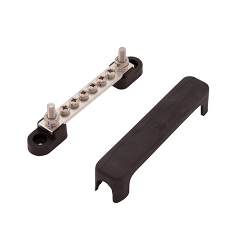
    I found these buss bars from DelCity which have ground connections at both ends of the bar with 6 spots to attach grounds from the loads (I anticipate actually putting more than one on a spot if need be):


    Here is the installation for the grounds at the rear of the car. I attached it to the rear IRS cage support:


    After installing the bar I used 8 gauge power wire left over from the power cables to attach the buss bar at both ends to the chassis giving the circuits attached two paths to ground.


    A little dielectric grease was applied as well

    Here is the finished version with the cover installed:


    I then added some braided wire wrap to cover up the "red".


    I have ordered 3 more of the buss bars to use in the dash and front of the car.

    Please let me know if you all see any issues with the plans here ...

    Carl
    Mk 4 Roadster
    October 25, 2012 - Kit Arrives
    April 8, 2013 - Build Starts
    August 23, 2015 - Rolling Chassis/Engine & Transmission Installed
    March 26, 2016 - Go Cart

  13. #213
    Member
    Join Date
    Mar 2012
    Location
    New Port Richey, Fl
    Posts
    77
    Post Thanks / Like
    Looks good I just ordered some of the bussbars from them too with a bunch of other stuff, I am doing my grounds the same front and rear but I run a large ground from the front to the back buss and the frame also. Just a habit from building off-road stuff not a fan of just using the chassis as the ground.
    But that's just a habit.

    Joe
    http://www.ffcars.com/forums/17-fact...d-finally.html
    http://www.ffcars.com/forums/17-fact...rts-build.html
    https://www.ffcars.com/threads/final...roject.645071/
    MK4 complete kit.
    351 Dart based 427, 4'' stroke by 4.125 bore.
    Twisted Wedge 11R heads Dual quad EFItech efi

  14. #214
    Carl carlewms's Avatar
    Join Date
    May 2012
    Location
    Nokesville, VA
    Posts
    1,125
    Post Thanks / Like

    ISIS Installation Continues

    I spent most of the day in the wiring department ...

    After receiving another goody bag from DelCity which included more of the bus (or buss I am darn not sure what way it is spelled in this context), I put the front one on top of the X member. Since the X member is round I had to shave off a bit of the base to get a better fit. Here are the results ... looks like the one in the rear but with black heat shrink instead of braided wrap.


    I also upgraded to some better eyelet connectors with built in heat shrink that were of a much better quality than the "auto" store variety.

    The next effort was directed at getting all the wiring run for the loads related to the front of the car ...

    Headlights
    Low Beams
    High Beams with smaller gauge wire to the instrument panel for the high beam LED
    Flash to Pass (Alternating)
    Parking Lights/Instrument Panel or Gauge Lights
    Turn Signals
    Left Turn with smaller gauge wire to the instrument panel for the left turn LED
    Right Turn with smaller gauge wire to the instrument panel of the right turn LED
    Start
    Ignition
    Horn
    Cooling Fan Override

    I still have to get the connections made up at the load ends and then get everything wire braided up.

    Here are some photos of the current mess ...


    The loom to go to the cockpit will actually be on the outside or below the 3/4 in square tube.

    Across to the PS of the car.


    Aft to the cockpit.


    The penetration through the front panel of the DS foot box will be protected and sealed with a grommet that will go on a small cover plate for what is normally the clutch cable penetration.

    Through the top of the DS foot box over the Wilwood pedal assembly


    The wire ties will be removed before the wire are bundle in the braided wire loom material.

    Then across the 2 by 2 to ... the only powered wire going all the way across the dash is the power to the MSD box (to be placed in the PS foot box) which is energized when the ignition is on. Taps off this wire also provide power to the ECU in the PS foot box. The other power goes to the starter solenoid which will be on the firewall engine compartment above the transmission tunnel (on the horseshoe).


    Carl
    Last edited by carlewms; 12-12-2014 at 11:32 PM.
    Mk 4 Roadster
    October 25, 2012 - Kit Arrives
    April 8, 2013 - Build Starts
    August 23, 2015 - Rolling Chassis/Engine & Transmission Installed
    March 26, 2016 - Go Cart

  15. #215
    Junior Member
    Join Date
    May 2014
    Posts
    6
    Post Thanks / Like
    Carl - nice build. I am a new forum member and just read through your whole thread. Look forward to your first start.

    Andy

  16. #216
    Carl carlewms's Avatar
    Join Date
    May 2012
    Location
    Nokesville, VA
    Posts
    1,125
    Post Thanks / Like

    ISIS Installation Continues

    This post is a out of order ...

    The order from McMaster-Carr arrived with the high temperature wire wrap insulation to install on the wiring traversing near the DS headers/exhaust. I decided to put the 12V power in one loom and the CAN cable in a separate loom and cover both from the POWERCELL to the dash including above the DS foot box.

    Part # 8994T13 High-Temperature Expandable Sleeving 1/2 in
    Part # 8994T11 High-Temperature Expandable Sleeving 1/4 in

    My only concern is this covering is off white/beige and will be a collector of oil and dirt. The solution is covering it with a section of standard black braided wrap.


    Since the multiple spade connectors also arrived I finished off the installation of the horns (McMaster-Carr Part # 72065K52 Piggyback Quick Disconnect Terminal, Fully Insulated, Expanded Barrel, 16-14 AWG).


    The wiring of the rear POWERCELL is much simpler. With the Muti-Wire Heat-Shrink Butt Splice 16-14 AWG from McMaster-Carr (Part # 7617K13). The branches for the right side parking and brake lights used these connectors and were much quicker to install than the ones used on the forward harness. The downside is it causes quite a lump at the point of connection.

    Prior to heat shrinking...


    After heat shrinking...


    After fooling around looking at different paths for the parking and brake light wiring I settled on the most accessible route I could find in case future repairs or modifications were needed. The loom going up the right side of the outer trunk panel, serves the license plate light and the trunk light (which will be on the trunk lid and activated off a pin switch on the hinge).


    The loom going down to the left serves the brake and parking lights.

    The tan wire is for the trunk light pin switch, the orange lead to the trunk light, and the yellow line is the power lead to the license plate light.


    The loom traverses to the DS under the lower panel of the trunk just above the jack bolts. The bolts will be replaced with shorter versions in the final assembly.

    Lastly, the grounds for the rear loads were hooked up to aft ground bus.


    Carl
    Mk 4 Roadster
    October 25, 2012 - Kit Arrives
    April 8, 2013 - Build Starts
    August 23, 2015 - Rolling Chassis/Engine & Transmission Installed
    March 26, 2016 - Go Cart

  17. #217
    Junior Member
    Join Date
    May 2014
    Posts
    6
    Post Thanks / Like
    Carl - what is the cost of the ISIS system versus traditional wiring?

    Andy

  18. #218
    Carl carlewms's Avatar
    Join Date
    May 2012
    Location
    Nokesville, VA
    Posts
    1,125
    Post Thanks / Like
    Andy,

    The upfront costs for ISIS are higher by far ...

    The ISIS 3 Cell System is $1,552.50 where as the Ron Francis System is $479 so it is about three times the upfront cost. I hope to recover some of the cost by selling my RF harness.

    While price is always a factor, for me the advantages of the ISIS outweighed the steep difference in costs. So far in the installation, the ISIS system has far less wiring to run, the fuse box and its associated connections (and points of failure) is illuminated, the number of relays used is reduced, the Built In Test Equipment (BITE) makes troubleshooting a much easier and since the functions are programmable, the manner in which each circuit acts (called personality in ISIS speak) can be modified as needed.

    For me there were business reasons as well since the system has applicability to what i do professionally.

    Carl
    Mk 4 Roadster
    October 25, 2012 - Kit Arrives
    April 8, 2013 - Build Starts
    August 23, 2015 - Rolling Chassis/Engine & Transmission Installed
    March 26, 2016 - Go Cart

  19. #219
    Out Drivin' Gumball's Avatar
    Join Date
    Feb 2011
    Location
    Blackberry Township, IL
    Posts
    2,653
    Post Thanks / Like
    Carl,

    Your build is coming along beautifully. Although I'm using the RF system, not ISIS, I really enjoy following this thread!

    Keep up the great work.
    Later,
    Chris

    "There are no more monsters to fear, and so, we have to build our own."
    Mk3.1 #7074

  20. #220
    Carl carlewms's Avatar
    Join Date
    May 2012
    Location
    Nokesville, VA
    Posts
    1,125
    Post Thanks / Like

    ISIS Installation Continues - Rear Section

    As noted in the previous post on the front, the power wiring to the rear POWERCELL is completed.

    After further reflection, I decided to install two filament lights in the rectangular Finish Line rear lights being installed on the car. The modification of the rectangular tail lights that currently only have one bulb and a reflector will be in a different post but has also been covered in numerous forums ... nothing really new from that perspective.

    This decision required adding another wire to the rear wiring harness from the POWERCELL to the two lights.

    With the right tools (meaning the right crimper) I found that with a little bit of patience and care, getting the weather pack connectors was pretty easy.


    This is the female side and when I get the mods done on the light fixture the male side will mate up to it forming a watertight connection easily disconnected to service the components or remove the body.

    Borrowing the idea from other forums, I used marine grade shrink wrap to bind the end of the braid with the wires. This marine grade shrink wrap has a built in adhesive that activates when heated which really seals penetrates the braid and binds it to the wiring.

    The wiring for the trunk light and the license plate light to the centerline of the rear trunk hoop is completed. I terminated it in a 3 wire weatherpack.


    The wiring setup is:

    Ground: Black
    Trunk Light: Orange
    License Plate Light: Yellow

    I need to finish up the CAN cable modifications (basically to cut out the excess wire) before wrapping up everything at the rear POWERCELL end of things.

    I still have to wrap the junctions in the wire looms with self vulcanizing tape but I wan to hold off in doing so until I have every thing tested just in case the wiring needs to be changed. Right now I have used wire ties to hold the braided wire wrap at the ends.

    Carl
    Mk 4 Roadster
    October 25, 2012 - Kit Arrives
    April 8, 2013 - Build Starts
    August 23, 2015 - Rolling Chassis/Engine & Transmission Installed
    March 26, 2016 - Go Cart

  21. #221
    Carl carlewms's Avatar
    Join Date
    May 2012
    Location
    Nokesville, VA
    Posts
    1,125
    Post Thanks / Like

    ISIS Installation Continues - The Front

    As it has evolved the wiring of the car has really falling into three distinct areas The front or engine compartment, the middle or dash and the rear or trunk.

    The front POWERCELL is completely wired with the exception of connecting the power up to the Mega Fuse Kit. The harness looms are completed to the loads with the exception of the weatherpacks.

    All the wiring from the POWERCELL is routed to the loads and the CAN cable is routed to the front POWERCELL. As these wires pass over the headers/exhaust piping, I first used high temperature expandable Sleeving to protect the wiring from the heat and then covered them with standard split braided wire wrap to protect the beige colored insulation and keep to the same overall appearance of having a black cover on all the wiring.


    The sleeving was sourced from McMaster-Carr:

    8994T13 1 Each High-temperature Expandable Sleeving, 1/2" Id, 10' Long
    8994T11 1 Each High-temperature Expandable Sleeving, 1/4" Id, 10' Long

    Here is a photo showing how the high temperature expandable sleeving is under the split braided wire wrap


    Here is a shot of the completed installation on the front of the DS foot box


    I used the access point normally reserved for the clutch cable to enter into the DS foot box


    This may be over kill on the wiring protection...

    I routed and installed the primary or positive wiring from the Mega Fuse Kit to the rear POWERCELL. As done on the DS the wiring is protected using high temperature expandable sleeving overlaid with the split black braided wire covering.


    The ring connectors were crimped on the wire then clear heat shrink was used to protect the junction to produce a good solid and waterproof junction.

    Carl
    Mk 4 Roadster
    October 25, 2012 - Kit Arrives
    April 8, 2013 - Build Starts
    August 23, 2015 - Rolling Chassis/Engine & Transmission Installed
    March 26, 2016 - Go Cart

  22. #222
    2bking's Avatar
    Join Date
    Jul 2013
    Location
    Garland, Texas
    Posts
    799
    Post Thanks / Like
    You have some well thought out ideas. I'll get my ISIS components in the next few days and am going to use some of your ideas. Keeping the heat from destroying the wiring, electronics, and tubes is challenging and we all struggle with it. Before I pull the trigger to order some of the sleeving you're using, I want to better understand what you are accomplishing with the way you are constructing the wire bundle leaving the foot box.

    I don't want to be demeaning with this comment as I am trying to follow the logic from a thermal view point. Just looking at the bundle itself, the internal temperature will reach the temperature of the external covering with no internal load. The reflective covering on the brake lines works there by reflecting the radiant heat from high temperature sources thus the brake line temperature is somewhat the same as the surrounding air temperature. The black covering on the wire bundles will absorb the radiant heat thus making the temperature of the bundle higher than the surrounding air. The insulation on the wires will fail when the bundle temperature reaches the rated temperature of the insulation. Current in the wires will increase the internal bundle temperature and the high temp sleeving serves to limit the heat transfer to the surrounding air.
    Last edited by 2bking; 05-22-2014 at 08:50 AM.
    King
    Roadster #8127, ordered 7/12/13, received 9/11/13
    http://thefactoryfiveforum.com/showt...4-Coyote-Build

  23. #223
    Carl carlewms's Avatar
    Join Date
    May 2012
    Location
    Nokesville, VA
    Posts
    1,125
    Post Thanks / Like
    King,

    A very good set of questions ... Not demeaning at all.

    Here are my thoughts...starting from the last point and working my way backwards.

    I, perhaps incorrectly, do not think that there will be much heat generated in the bundle of wires going to the MASTERCELL and loads in the dash. The worst case condition for heat generation in the bundle would be at night and in the rain. Under those conditions, the gage lights would be on and the windshield wiper motor on in addition to the power going to the ECU and MSD box. While I do not have test data to back that up I don't think that will be a major heat source.

    With respect to the heat transfer across the black braid wrap and fiberglass insulation:

    I agree that a reflective cover like I have on the brake lines would better handle the radiant heat transfer and I may have to add it at some point. I also agree that the black will absorb more of that radiant heat.

    Here is where I believe the high temperature sleeve helps...

    The heat generated from the headers/exhaust transfer across the air gap and the braided black wire loom but does not transfer across the insulation enough to cause damage/failure of the wires as long as the temperature on the outside does not exceed the 1000 deg F in the spec below.

    The characteristics of the high temperature expandable sleeve from the McMaster-Carr website states the sleeving offers

    "Protection from temperatures up to 1000° F is combined with the ability to accommodate irregularly shaped objects. Sleeving is fiberglass and resists burning. Use to protect hose and cable located near ovens and furnaces. Temperature range is -60° to 1000° F."

    In trying to determine what temperatures we could expect at the headers, I checked on line sources, and while there are many variables the highest temps at the header junction was around 708 deg F in a study on a V8 powered Silverado. I don't expect to exceed 1000 deg F at the wire loom location.

    One additional data point, the RF harness uses the same routing and is not insulated.

    Thanks for asking the question.

    Carl
    Mk 4 Roadster
    October 25, 2012 - Kit Arrives
    April 8, 2013 - Build Starts
    August 23, 2015 - Rolling Chassis/Engine & Transmission Installed
    March 26, 2016 - Go Cart

  24. #224
    Carl carlewms's Avatar
    Join Date
    May 2012
    Location
    Nokesville, VA
    Posts
    1,125
    Post Thanks / Like

    The Good Bad But Mostly Ugly

    Not much progress made...but lots of lessons learned!

    The sad saga centers around on small piece of sheet metal about 5 by 7 inches which I have attempted to shape into a back cover and mounts for LED bulbs for the rectangular tail lights.

    Part of the build process for me has been learning new skills...cold forming aluminum sheet metal parts has been one of them so I figured I would start with this relatively simple part...at least that is what I thought when I started the process.

    I started with a template provided by Chris over on the ffcars.com forum. I modified the template to make it waterproof.

    I fabricated a form and then planned on shaping the part around the form to create the housing. I made a form from 2 by 4 pine which I rolled over the edges to form a smooth rolled edge at the top of the part. The cold forming part of the process worked out pretty well. I used .025 in big box aluminum which made it fairly ease to hammer the metal.

    Things went wrong when I tried another skill I am trying to acquire...brazing aluminum. I wanted to make a weather proof version of the housing, so I thought I could fill in the holes and seams in the housing with the aluminum brazing rod. Between my beginner's skill set and the rod I had it turned my nicely formed box into a mess. When brazing aluminum it is really easy to blow the thin aluminum right out...which I did on several occasions. The working temperature of the rod was very close to the melting point of the aluminum making getting the right amount of filler on the seams challenging. I ended up with a verrrry uneven surface. :crazy2.

    After all that I decided that my cold forming and brazing skill set need mucho improvement, practice and a better rod to use (which I found online and ordered).

    My second attempt was to go back to the way the template was intended to be fabricated; bend it and rivet together. I did decide to add another step; polishing the inside of the gap housing to make it more reflective. I got it all together and went to fit it on the lens housing and found the ultimate reason this part was also going on the Wall of Shame.

    The housing is attached to the lens base with two nuts on two threaded studs on the base. My second attempt was just a hair too big to get the nuts on the studs. By the way I went back and checked my first masterpiece and it would not have fit either. Lesson Learned: Always check the templates and measure the real part to make sure you got up it right!

    My third attempt is in progress after measuring the stud location (which clearly I should have done first). It turned out that for the studs on my lights I needed to reduce the housing size by .25 inches.

    Photos to follow...

    Carl
    Mk 4 Roadster
    October 25, 2012 - Kit Arrives
    April 8, 2013 - Build Starts
    August 23, 2015 - Rolling Chassis/Engine & Transmission Installed
    March 26, 2016 - Go Cart

  25. #225
    Carl carlewms's Avatar
    Join Date
    May 2012
    Location
    Nokesville, VA
    Posts
    1,125
    Post Thanks / Like

    The Good, the Bad and the Ugly

    Here are the photos of the items going up on the Wall of Shame ...

    The first is the attempt at cold forming and brazing ...

    The form is on the left ... a bit burnt from the brazing attempts. The "results" are on the right.


    The filler from the brazing is much stronger than the aluminum sheet and this was after I ground some of it off ...


    A couple of photos showing where the thin aluminum got hot enough to melt and blow out.


    Lessons Learned

    1. My "fat fingered" technique needs a lot of practice before considering again for a part that is really going on to the car;
    2. Hand forming will require a lot of planishing and grinding to clean up the piece prior to priming and painting;
    3. If brazing, make sure to that the filler rod melts or works at a much lower temperature than the base metal ... the stuff I bought at the big box store was too close to the melting point of the base aluminum;
    4. Make sure to have an assortment of grinding discs for the Dremel or die grinder including some that can get in the tight corners;
    5. Cold forming the aluminum takes a lot longer than bending and riveting ... but if I could have done it properly would have looked a lot more authentic and be more weather proof; and,
    6. You need a boat load of patience to fabricate this way ....


    Carl
    Mk 4 Roadster
    October 25, 2012 - Kit Arrives
    April 8, 2013 - Build Starts
    August 23, 2015 - Rolling Chassis/Engine & Transmission Installed
    March 26, 2016 - Go Cart

  26. #226
    Senior Member DaleG's Avatar
    Join Date
    Mar 2013
    Location
    Prescott, AZ; formerly from the Bay Area
    Posts
    829
    Post Thanks / Like
    6. You need a boat load of patience to fabricate this way ....

    So, so true.
    SOLD 03/2013: MK II #5004: 5.0 EFI: 8.8, 3.55, E303, TW heads, GT40 intake, 24#, 70mm MAF

    Ordered MK IV Coyote Complete Kit.

  27. #227
    Out Drivin' Gumball's Avatar
    Join Date
    Feb 2011
    Location
    Blackberry Township, IL
    Posts
    2,653
    Post Thanks / Like
    Carl - Man, I give you credit for trying that... I took the easy way out with the originals that I made and just riveted them after applying a good bead of non-silicone 3M seam sealant. I also drilled a weep hole in the bottom, in the event that some moisture makes it into the housings. Remember that these will be mounted high in the rear quarter and that the splash guards (rear elephant ears) will protect them from the majority of the spray if you drive in the rain.

    Also, make sure to protect the wiring pigtails where they exit the housing and connect to the main harness.

    I can't wait to see the next attempt - the second version always seems to be much better than the first! Keep at it, man, and they'll turn out great.
    Later,
    Chris

    "There are no more monsters to fear, and so, we have to build our own."
    Mk3.1 #7074

  28. #228
    Carl carlewms's Avatar
    Join Date
    May 2012
    Location
    Nokesville, VA
    Posts
    1,125
    Post Thanks / Like
    Chris,

    Thanks for the comments ... here are some preliminary photos of the final version, i.e. work in progress:

    View from the rear of the fitting ... I will round off the corners before painting


    Side view ... I ended up having to increase the depth of the cover to accommodate the longer LEDs


    From the front side of the cover ...


    I still need to put in the divider between the two bulbs and the weep hole.

    Carl
    Mk 4 Roadster
    October 25, 2012 - Kit Arrives
    April 8, 2013 - Build Starts
    August 23, 2015 - Rolling Chassis/Engine & Transmission Installed
    March 26, 2016 - Go Cart

  29. #229
    Senior Member
    Join Date
    Feb 2011
    Location
    Myrtle Beach, SC
    Posts
    2,108
    Post Thanks / Like
    Nice work Carl! They should work great.

    Regards,

    Steve

  30. #230
    Senior Member CraigS's Avatar
    Join Date
    Feb 2011
    Location
    Blacksburg, Va
    Posts
    4,730
    Post Thanks / Like
    Carl I just scrolled though this last page in your thread to get to the new stuff. Your work is top notch but I have just one constructive comment. Move those horns. I know you are going for a somewhat period look, but unless those horns are there on particular oldie that you are emulating, I would move em. The horns and their wires are not something you want to look at every time you open the hood. I would hang them off the lower part of the "X" frame or off some of the 3/4x3/4 tubes that support the front of the body.
    FFR MkII, 408W, Tremec TKO 500, 2015 IRS, DA QA1s, Forte front bar, APE hardtop.

  31. #231
    Carl carlewms's Avatar
    Join Date
    May 2012
    Location
    Nokesville, VA
    Posts
    1,125
    Post Thanks / Like
    Craig,

    Thanks for the suggestion. It would sure clean up that area a bit...

    Where did you put your horns?

    Carl
    Mk 4 Roadster
    October 25, 2012 - Kit Arrives
    April 8, 2013 - Build Starts
    August 23, 2015 - Rolling Chassis/Engine & Transmission Installed
    March 26, 2016 - Go Cart

  32. #232
    Senior Member CraigS's Avatar
    Join Date
    Feb 2011
    Location
    Blacksburg, Va
    Posts
    4,730
    Post Thanks / Like
    Mine are on a corner of that big plate that caps off the front of the 4 inch tube. Mine is an older MkII so that plate may be a different shape than yours. I just tried to find a spot where they wouldn't be too visable. When you open the hood that "X" frame is right there staring at you.
    FFR MkII, 408W, Tremec TKO 500, 2015 IRS, DA QA1s, Forte front bar, APE hardtop.

  33. #233
    Carl carlewms's Avatar
    Join Date
    May 2012
    Location
    Nokesville, VA
    Posts
    1,125
    Post Thanks / Like

    Rectangular Tail Light Covers ... Part 1

    I spent a little time out in the garage making the second rectangular tail light cover for the roadster. This one went a little faster and looks better that the first one.

    I decided to layout the entire process in consecutive posts ...

    1. With all the components on hand (sheet metal, LEDs, and bulb holders), measure to make sure you have enough room for the combination of LED's and bulb holder;


    The LEDs are slightly longer than the normal incandescent bulb;

    2. After measuring, I mocked up a cardboard version to make sure everything fit;


    I took the template created by Chris on ffcars.com and added tabs to seal off the sides of the cover and I increased the height of the wall from 1.25 in to 1.75 in to accommodate the longer LED bulbs;

    3. The new template was used to figure out how to do the bends and mockup;


    Carl
    Mk 4 Roadster
    October 25, 2012 - Kit Arrives
    April 8, 2013 - Build Starts
    August 23, 2015 - Rolling Chassis/Engine & Transmission Installed
    March 26, 2016 - Go Cart

  34. #234
    Carl carlewms's Avatar
    Join Date
    May 2012
    Location
    Nokesville, VA
    Posts
    1,125
    Post Thanks / Like

    Rectangular Tail Light Covers ... Part 2

    4. The measurements were then transferred to the .025 in aluminum sheet and the four main bends were scribed to make bending easier;


    5. Using a hand shear, all the cuts were made;


    After making the cuts and the associated bends I realized that this was an area were being more exact can be crucial to the outcome. Since these are hidden under undercoating and inside the fender, it is not worth redoing again.

    6. Bending the cover: First the long sides were bent on the brake, then the tabs, and lastly the short sides;


    7. All the tabs were riveted with 1/8 in aluminum rivets and the holes for the bulb holders were drilled with a step bit;


    8. The bulb holders were then riveted on one side and clekoed on the other prior to painting with rubberized undercoating;


    I removed the wires from the plugs and inserted paper plug to keep the coating material out of the holders;

    9. After spraying with two coats, the cleckos were removed and this will give me a clean spot to install the grounds;


    10. The ground connection is riveted on to the base and the weather pack connection installed.


    I will touch up the rubberized coating when I finally get them installed on the body ...

    Carl
    Mk 4 Roadster
    October 25, 2012 - Kit Arrives
    April 8, 2013 - Build Starts
    August 23, 2015 - Rolling Chassis/Engine & Transmission Installed
    March 26, 2016 - Go Cart

  35. #235
    Senior Member MPTech's Avatar
    Join Date
    Feb 2011
    Location
    St. Louis, MO
    Posts
    1,184
    Post Thanks / Like
    Blog Entries
    8
    Carl, your lights look great! One piece of advice, cut the side tabs down as much as possible. One side will press against the inside of the fender curve and the other side will press against the trunk aluminum panel. I cut mine down before install, it was a tighter fit once everything was permanent and after applying a couple coats of truck-bed liner, it got even tighter. Just FYI.

    Here's my install & setup, for any further help.
    Installed my new rectangular / LED tail lights

    Also, I'm trying to figure out a way to improve the lighting (I really didn't think this would be a problem, but several fellow club members have pointed out that my brake lights are difficult to see!).
    I installed (4) "1157-PCB-x36: 36-LED 1157 PCB Lamp 1157-PCB-R36-WV: Red 100 Degree" from www.superbrightleds.com.
    They are VERY bright outside of the lens, but I think the rectangular lens significantly restricts them and part of the lens is really designed to be a reflector more than a lens.
    They said they are hard to see in the sunlight.

    Just be aware that it may be an issue. Mine looked plenty bright in the garage and at night, but more than a couple guys have told me they are difficult to see in bright sunlight. This has me concerned and I'm trying to identify and solution.
    F5R #7446: MK4, 302, T5 midshift, 3.55 Posi IRS, 17" Halibrands
    Delivered 4/4/11, First start 9/29/12, Licensed 4/24/13, off to PAINT 2/15/14!! Wahoo!

  36. #236
    Carl carlewms's Avatar
    Join Date
    May 2012
    Location
    Nokesville, VA
    Posts
    1,125
    Post Thanks / Like
    MPTech,

    Thanks for the comments and update. Since I am using a different bulb with a reflector it might make a difference but I will be sure to check to see and will post some photos in the sunlight.

    Carl
    Mk 4 Roadster
    October 25, 2012 - Kit Arrives
    April 8, 2013 - Build Starts
    August 23, 2015 - Rolling Chassis/Engine & Transmission Installed
    March 26, 2016 - Go Cart

  37. #237
    Out Drivin' Gumball's Avatar
    Join Date
    Feb 2011
    Location
    Blackberry Township, IL
    Posts
    2,653
    Post Thanks / Like
    Carl,

    Great job on improving the design of the housings... I like the rubberized undercoating, too, and will add that to mine before final installation.

    As for the brightness issue - that's been a complaint since these lights were in production. My brother has a late '50s MGA with a similar light design on the rear end of the car and he still occasionally gets comments from other motorists that his lights are difficult to see.

    While I agree the brighter the better, I think some of it is that we, as drivers, have become accustomed to bright lights, so the old-style single bulbs don't catch our attention as much during the day.

    Great job so far - looking forward to more updates.
    Later,
    Chris

    "There are no more monsters to fear, and so, we have to build our own."
    Mk3.1 #7074

  38. #238
    Senior Member
    Join Date
    Feb 2011
    Location
    Myrtle Beach, SC
    Posts
    2,108
    Post Thanks / Like
    Carl-

    Really nice improvement over the first design. I really like the idea of LEDs where practical for all the same reasons you have already discussed.

    I bet when you get finished that doing a side-by-side comparison to another non-LED car, it will be a big difference, and worth all the extra work!

    Very nice job. Thanks for sharing your progress!

    Regards,

    Steve

  39. #239
    Carl carlewms's Avatar
    Join Date
    May 2012
    Location
    Nokesville, VA
    Posts
    1,125
    Post Thanks / Like

    Glove Box Question

    It's been a while since a post...but then it's been a while since I've gotten back into the garage.

    I have decided to add a shallow glove box to the SC dash and am planning on an installation similar to MPTech and CCsrC postings.

    In looking at all the photos I have found it difficult to tell if the cover sits flush or proud of the dash itself.

    Please help me out here and post a few photos of the fit up against the dash.

    Carl
    Mk 4 Roadster
    October 25, 2012 - Kit Arrives
    April 8, 2013 - Build Starts
    August 23, 2015 - Rolling Chassis/Engine & Transmission Installed
    March 26, 2016 - Go Cart

  40. #240
    Carl carlewms's Avatar
    Join Date
    May 2012
    Location
    Nokesville, VA
    Posts
    1,125
    Post Thanks / Like
    Its been a while since I have updated the thread ... been busy starting an new company (:crazy2 at the age of 61 to do so but ...)

    After deciding to go with the SC version of the dash and cutting most of the holes for the instruments and switches, I finished up the last few holes (slightly oversized to accommodate the leather).

    I wanted to add a glove box to the dash ... and, like other things on my build ... I just could not go out and buy a glove box and just use it. Several vendors offer glove boxes for FFR but nooooo I just had to build my own. Thanks to those on here and the other forum for all the threads on this subject.

    With the template from others over on the FFR forums (which I expanded slightly) I cut out the cover from .04 in T6-6061 aluminum panel (the same as the FFR supplied dash).


    I used this as a template to cut out the dash ... here is the full dash laying atop the leather purchased to cover the dash.


    I purchased the hide online from www.leatherhidesonline.com after getting some samples to match up the leather to my FFR seats. The leather will also be used on the door cards and potentially on the transmission tunnel top.

    After cutting the dash for all the switches and instrumentation, cutting the large hole for the glove compartment was a bit disconcerting.

    I tackled the door next but after a couple of more items were created to go on the Olde Goat's Garage Wall of Shame, i decided to regroup and focus on the compartment itself. I want a shallow compartment because of the heater or potential air-conditioning installation. Here is the template I prepared ...


    Here is the template "installed" on the dash ...


    The back or front of the comportment was cut out of .04 in T6 6061 aluminum and then I used a .02 in thick aluminum to create the walls of the box. ...

    Front view:


    Back view:


    I found some countersunk rivets from McMaster Carr (Part Nr: 97447A210, Countersunk, 1/8" Diameter, .092"-.125" Material Thickness" that I will use to attach the box to the dash and assemble the box so that the front of the dash and the inside of the box remain smooth.

    Have a Great Day!

    Carl
    Mk 4 Roadster
    October 25, 2012 - Kit Arrives
    April 8, 2013 - Build Starts
    August 23, 2015 - Rolling Chassis/Engine & Transmission Installed
    March 26, 2016 - Go Cart

Page 6 of 22 FirstFirst ... 4567816 ... LastLast

Posting Permissions

  • You may not post new threads
  • You may not post replies
  • You may not post attachments
  • You may not edit your posts
  •  

Replica Parts

Visit our community sponsor