BluePrint Engines

Visit our community sponsor

Thanks Thanks:  0
Likes Likes:  0
Page 1 of 5 123 ... LastLast
Results 1 to 40 of 193

Thread: Ninjanick's 818S Build Thread

  1. #1
    Senior Member
    Join Date
    Oct 2014
    Location
    Redondo Beach, CA
    Posts
    161
    Post Thanks / Like

    Ninjanick's 818S Build Thread

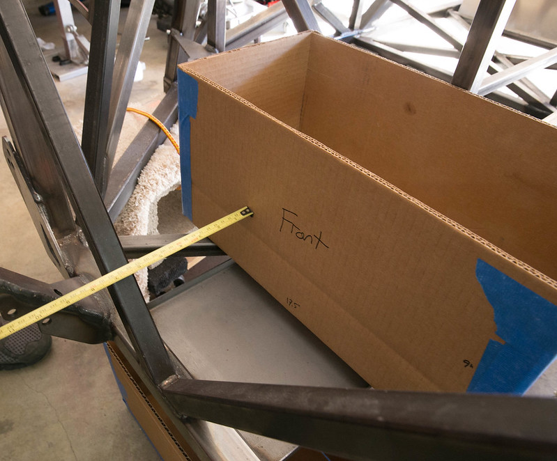
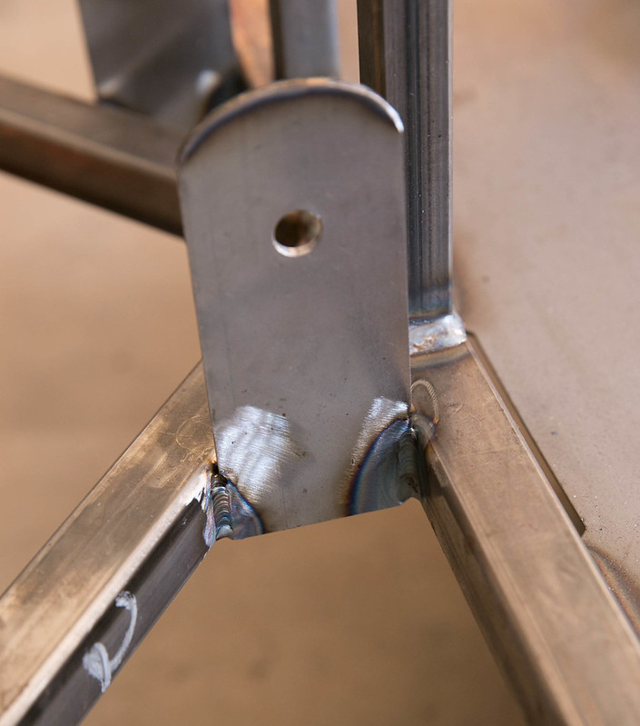
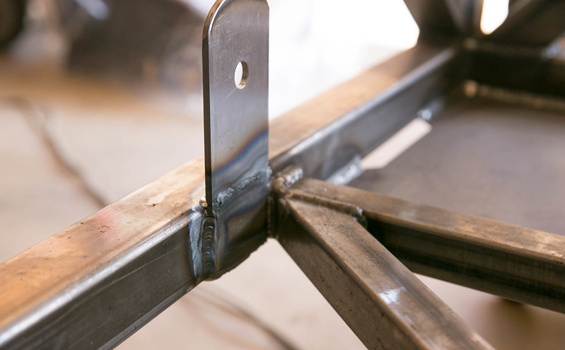
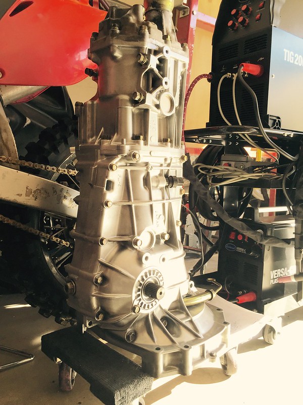
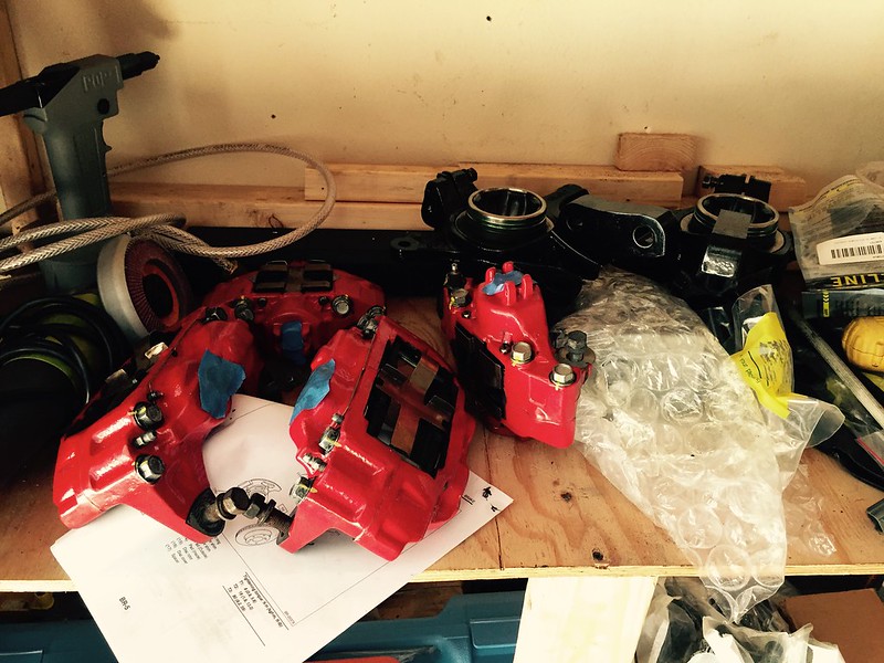
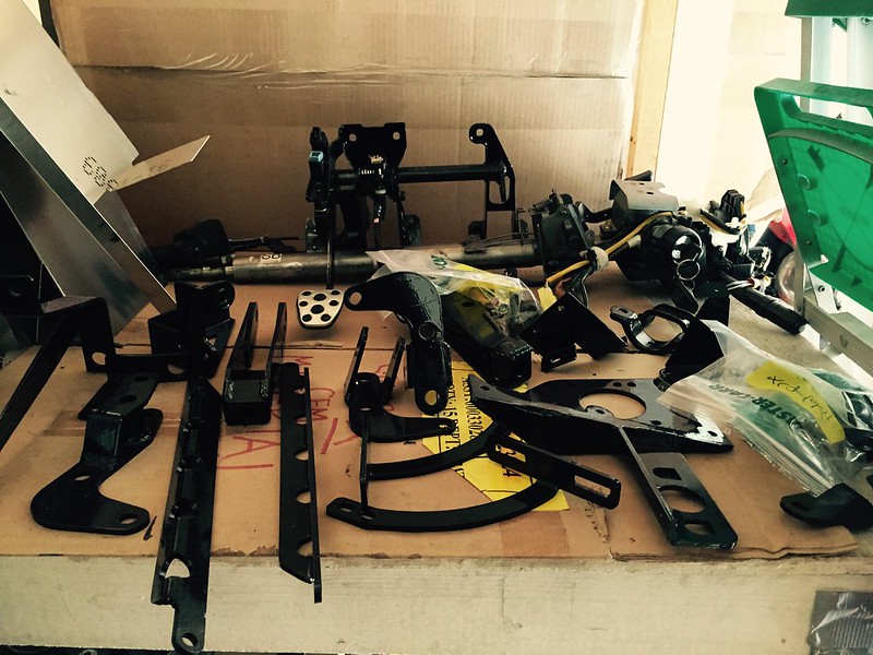
    I've been wanting to build an FFR for quite some time, but never really pulled the trigger. I don't know how well I will maintain this thread, but my build finally started when I took delivery of SN #258 12/18/14. The excitement and anxiety are still with me. My daughter and I plan to make this one unique. So far is been lots of unpacking and cleaning the donor parts. I'd like to thank Erik for his inspirational build and letting me see his 818e first hand.

    https://www.flickr.com/photos/ninjan...7649964158941/

  2. #2
    Senior Member
    Join Date
    Oct 2014
    Location
    Redondo Beach, CA
    Posts
    161
    Post Thanks / Like


    Attached Images Attached Images
    Last edited by ninjanick; 12-28-2014 at 02:44 AM.

  3. #3
    Senior Member
    Join Date
    Oct 2014
    Location
    Redondo Beach, CA
    Posts
    161
    Post Thanks / Like

  4. #4
    Senior Member
    Join Date
    Jan 2012
    Posts
    1,112
    Post Thanks / Like
    Did you just get your kit or did you request the white body, I thought they switched to the red bodies. Its nice to have another 818 builder in socal

  5. #5
    Senior Member AZPete's Avatar
    Join Date
    Feb 2011
    Location
    Scottsdale, AZ
    Posts
    2,374
    Post Thanks / Like
    Congrats, Nick, on the start of a fun trip building your 818.
    818S/C : Chassis #25 with 06 WRX 2.5 turbo, ABS, cruise, PS, A/C, Apple CarPlay, rear camera, power windows & locks, leather & other complexities. Sold 10/19 with 5,800 miles.
    Mk3 Roadster #6228 4.6L, T45, IRS, PS, PB, ABS, Cruise, Koni's, 17" Halibrands, red w/ silver - 9K miles then sold @ Barrett-Jackson Jan 2011 (got back cash spent).

  6. #6
    Senior Member Frank818's Avatar
    Join Date
    Jun 2013
    Location
    QC, Canada
    Posts
    5,732
    Post Thanks / Like
    Nick, welcome home (the forums ).
    Don't worry, you will make it unique, all 818 are unique, unlike all say Porsches, Ferraris, Fords, etc.. That's the beauty of a kit car.
    Frank
    818 chassis #181 powered by a '93 VW VR6 Turbo GT3582R
    Go-karted Aug 5, 2016 - Then May 19+21, 2017
    Tracked May 27/July 26, 2017
    Build time before being driveable on Sep 27, 2019: over 6000h
    Build Completed Winter 2021

  7. #7
    Senior Member
    Join Date
    Oct 2014
    Location
    Redondo Beach, CA
    Posts
    161
    Post Thanks / Like
    I ordered one of the 2 they had in overstock

  8. #8
    Senior Member
    Join Date
    Oct 2014
    Location
    Redondo Beach, CA
    Posts
    161
    Post Thanks / Like
    Build Specifications:

    WARP11HV DC Motor mated to 5MT Transmission
    Soliton1 Controller
    94 - 96 CALB CA 60aH batteries
    Charger (haven't decided yet, but most likely the Isolated version from EMotorwerks)
    DC/DC (haven't decided yet)
    LG 10.1 Tablet for battery monitoring and statistics
    NRG interior (courtesy of Erik/33Machines)

  9. #9
    Senior Member
    Join Date
    Jan 2014
    Location
    Ontario, Canada
    Posts
    141
    Post Thanks / Like
    Quote Originally Posted by ninjanick View Post
    Build Specifications:

    WARP11HV DC Motor mated to 5MT Transmission
    Soliton1 Controller
    94 - 96 CALB CA 60aH batteries
    Charger (haven't decided yet, but most likely the Isolated version from EMotorwerks)
    DC/DC (haven't decided yet)
    LG 10.1 Tablet for battery monitoring and statistics
    NRG interior (courtesy of Erik/33Machines)
    Hey Nick, welcome!
    Nice to see another electric build. I almost went DC, but decided on AC. . .which was an expensive decision when I already owned all the stuff to do it in DC. lol.
    Question; why CALB CA series? I mean I love these cells for a "normal car build", but the CAM series are 38% smaller and 20% lighter for the same energy. Gonna be a challenge to fit the CA's I would think?? Also, I think you will be under-powering the Soliton1 even at 10C. Even the CAM series aren't what I would call a high performance battery although they would be much better suited to a small car build like this.

    CALB will be releasing the CAM25-P (power cells in a few months) 96P-2S string of these 25Ah cells would help a lot.

    Why going with the 5 speed?

    Looking forward to see your progress.

    Gary

  10. #10
    Senior Member
    Join Date
    Oct 2014
    Location
    Redondo Beach, CA
    Posts
    161
    Post Thanks / Like
    Quote Originally Posted by Gary Livingston View Post
    Hey Nick, welcome!
    Nice to see another electric build. I almost went DC, but decided on AC. . .which was an expensive decision when I already owned all the stuff to do it in DC. lol.
    Question; why CALB CA series? I mean I love these cells for a "normal car build", but the CAM series are 38% smaller and 20% lighter for the same energy. Gonna be a challenge to fit the CA's I would think?? Also, I think you will be under-powering the Soliton1 even at 10C. Even the CAM series aren't what I would call a high performance battery although they would be much better suited to a small car build like this.

    CALB will be releasing the CAM25-P (power cells in a few months) 96P-2S string of these 25Ah cells would help a lot.

    Why going with the 5 speed?

    Looking forward to see your progress.

    Gary
    I chose the CALB CA 60aH mainly for cost. It fits my range and power requirements at only ~$7K. The CALB CAM series would be ~$13K. I'm not completely confident I will end up with prismatics as my last traction pack. I'm still researching the idea of making my own Headway or 18650/26650 traction pack. However, both these types of cells require more elaborate setups. I'm curious to see if Tesla's Gigafactory drives cost of Lithium cells down further ... possibly develop a new cell technology that I could upgrade in the future. For now the CALB CA 60aHs will "fit" both on the frame and in my budget.
    Do you have any specs on the CAM25-P? Does it have a higher predicted discharge rate?
    Running through some rough calculations and interpolating some of NetGain's data, I can achieve an max of ~190KW at about 10-12C. The CALB CAs should be able to handle that rate of discharge for brief moments (<10s). Cell degradation might happen a little sooner, but who knows ... maybe in 2 - 3 years I change powertrain.
    As for why transmission ... it saves me time sourcing and modifying a final drive more suited to the WARP11HV. I was thinking about a PowerGlide mated to the 11HV, but cost was one thing ... modifications to get it to fit were another.
    I've subscribed to your thread and I am anxious to see how your build unfolds. Right now, I'm done prepping all donor parts and am now modifying the frame to accept the DC motor as well as the custom battery boxes. Once done, I'll push the frame over to powdercoat.

  11. #11
    Senior Member
    Join Date
    Jan 2014
    Location
    Ontario, Canada
    Posts
    141
    Post Thanks / Like
    Hey Nick,

    Ya, I hear you about the cost. U gotta do what you can, man. I have some dimensions on the CAM25-P. They are suppose go give up 25C, I've heard 30C also. . . we'll see. I have a poorly supported theory that the smaller capacity prismatics give up a bit better C rate than the larger ones of the same chemistry purely due to relative conductor size. That can only help. . . including your 60Ah cells. It's true you can do 190 volts with Helwig split brushes so, 190kw with the 1000 amp soliton1. I'm a bit hesitant to think your pack will do that though. Have you considered voltage drop? Seems from the math that to hit that number, you are figuring the nominal voltage instead of a sagged level. I know you are in the warmer climate. . .which is a huge boon for discharge BTW.
    One thought you may consider is a small booster pack of similar chemistry, high discharge rate cells. I built a smallish capacity booster pack for my truck with A123 32157's. They will do 60 C and are absolute brutes for punishment. These have screw terminals so are not so hard to build into a pack. Finding these with screws is tough now, but you can find the smaller 32113's with screws and these will give up 250 all day. I built an accessory battery with these cells. As a booster pack, hooked in parallel, they will put it out. . .save the CALBS and recharge when you lift your foot off the pedal. Even a 2P pack of these small cylindrical cells in parallel with your calbs would stiffen the voltage and cough up the current. I can show you some pics of what I built if you're interested.

    All the best....

  12. #12
    Senior Member
    Join Date
    Oct 2014
    Location
    Redondo Beach, CA
    Posts
    161
    Post Thanks / Like
    There isn't a lot of data I could find on the CA cells, but I would expect them to perform better than the previous SE model. Some data online seems to indicate the SE models have a voltage drop around ~20%. With a rough spreadsheet I figured in about 15% voltage drop. With the Soliton 1, I have a max input voltage of 340VDC. At full charge (~3.55V per cell at 96s1p configuration), I'd get ~340VDC. Nominal voltage would ~307VDC and with voltage sag (15%), I'd be ~260VDC. I took some test data for the WARP9 motor since I didn't find any WARP11HV data, but the armatures are similar so I figure the voltage requirement is roughly the same. I will limit the battery pack current to ~720A which should allow me to supply 1000A to the motor up to about 3500RPM, from there it tapers off to ~680A motor side at ~270VDC which should give me ~5000RPM. Max motor power should be ~188KW. This doesn't take into motor and drivetrain efficiencies, which should knock that done to ~160-170KW? With the Soliton1 current limit (battery) set to 720A, I doubt I'll be drawing that much current for very long.
    That being said, I'd like to look at your booster pack! I'm curious to know how a booster pack would function. So you have a smaller capacity (same voltage) pack wired in parallel to stiffen the main traction pack. How does/would the different cells affect overall capacity? Do you need separate chargers or an elaborate BMS to switch between the 2? I was thinking of using Headway cells, but the total volume and weight savings is really outweighed by the complexity of the cell pack. 2 screws and some bus bar is about as simple as you can get.
    Where can you purchase CAM25-P cells?

  13. #13
    Senior Member
    Join Date
    Jan 2014
    Location
    Ontario, Canada
    Posts
    141
    Post Thanks / Like
    If you ask an engineer what temperature water boils at, he might ask you back, "at what pressure?" Similarly, voltage drop has everything to do with temperature of the cells. If you ran it down the track a few times, you might get close to that number but I would be surprised. 15% at 12C sounds like a stretch but hey. . warm them up see. Ive seen larger capacity CA cells tested that dropped 38% at 12C. At ambient temps of 75F I expect you may see 22 to 25% on the smaller 60Ah.
    When sizing these things, battery selection has everything do with what you want from the car. If you want to drag 1/4 mile, you go for 150 to 200C rate poly with a 150 lb or something, pack. Of course you have little range. Getting great performance and range is a little trickier. Many of the larger capacity cells don't have the discharge rate. That's why I built my booster pack. Then the challenge is to keep from melting your motor. DC series wound are the kings of drag racing. . . but that 11" motor is still only maybe 15hp continuous rated. Get a good blower on it to help. It should be a pretty good combination though. . since the car is so light, you will have a hard time loading that motor heavily for very long.

    As for overall capacity it is cumulative in parallel. So, built at the same voltage, if the booster pack had a capacity of say 10Ah, this would add to your 60Ah for a total capacity of 70Ah.

    You don't need any additional charger. Its the same voltage. Chargers for LiFePo4 have a pretty basic CC switching to CV charge algorithm. Chargers don't stop based on energy in, but rather on the voltage level. So, it works fine. I would not use a BMS on LiFePo4. . . and you don't need one for booster pack any more than you do for a range pack.

    The CAM25's aren't ready for prime time yet. . . but I'm told they are close. A few months perhaps. The Liuyan supercapacitor hybrid prismatics are suppose to be even a bit better. . . which would be a good cell for not needing a booster pack. They will do 25 to 30C rate. I'm considering these also. I do have a pretty good booster pack though, so I could live with a lower discharge range pack combo. Not decided yet.

    Cheers

  14. #14
    Senior Member
    Join Date
    Jan 2014
    Location
    Ontario, Canada
    Posts
    141
    Post Thanks / Like

    A123 cylindrical cells - 60C burst 30C continuous

    Here's a few shots of my booster pack. These are 32157's with screw studs. Also, a shot of the 32113's with screw studs I used for an accessory battery.
    Attached Images Attached Images

  15. #15
    Senior Member
    Join Date
    Oct 2014
    Location
    Redondo Beach, CA
    Posts
    161
    Post Thanks / Like
    With a booster pack of different capacity, how would the discharge profile look like for each pack? I would assume the controller would pull power equally from each pack if the resistance were the same. With a "less saggy" booster pack, the resistance would be lower which would draw more current from the booster pack? I like the idea of a small booster pack as I can't fit 100aH CALB CAs ... not without major modifications to the frame. Have you tried the Headway 40152 cells? I was going to play with a few in 4s2p configuration for my 12VDC system.
    What are the dimensions for the CAM25s? I would like to plan out my battery box mounts now prior to powder coating, but maybe I should hold off ...

  16. #16
    Senior Member
    Join Date
    Jan 2014
    Location
    Ontario, Canada
    Posts
    141
    Post Thanks / Like
    I just type a long reply and lost it. arghhh! This one will be shorter....

    The booster pack is lower resistance so, depending on capacity, it will give up a larger percentage of the current initially. When you let off, the calbs will "charge" them as they equalize voltage. So, make sure you add cooling fans if you build one.

    Haven't used Headways.. . .seems there is always some weak cells in a pack. Quality control is not so great last I heard. Perhaps if you cycle tested them, and checked resistance, you could weed out any weak ones.

    I will get the dims of the CAM25-P cells for you, I have it written down.

  17. #17
    Senior Member
    Join Date
    Jan 2014
    Location
    Ontario, Canada
    Posts
    141
    Post Thanks / Like
    CAM25-PFI = 25 x 126 x 148mm

    0.85kg

    Not as energy dense as the "E" models. They tend to optimize for energy or power density.

  18. #18
    Senior Member
    Join Date
    Oct 2014
    Location
    Redondo Beach, CA
    Posts
    161
    Post Thanks / Like
    Is that 148mm in length or height?

  19. #19
    Senior Member
    Join Date
    Jan 2014
    Location
    Ontario, Canada
    Posts
    141
    Post Thanks / Like
    That is the height.

    Cheers

  20. #20
    Senior Member
    Join Date
    Oct 2014
    Location
    Redondo Beach, CA
    Posts
    161
    Post Thanks / Like
    Cleaned and painted the transmission


    Painted and re-assembled brake calipers


    Wired in dedicated 220VAC for charger (to be purchased and installed) and welder

  21. #21
    Senior Member
    Join Date
    Oct 2014
    Location
    Redondo Beach, CA
    Posts
    161
    Post Thanks / Like
    Painted all miscellaneous parts found in boxes. Used POR-15 gloss black.

  22. #22
    Senior Member
    Join Date
    May 2013
    Location
    Colombia
    Posts
    222
    Post Thanks / Like
    I wonder when 818se builds will outnumber the gas engine builds... Nice! A DC build! It looks like you caught Gary thinking about batteries. I'm glad he posted all that stuff here. It sounds like I might benefit from the new CAM cells, we'll see.

  23. #23
    Senior Member Bob_n_Cincy's Avatar
    Join Date
    Sep 2012
    Location
    Cincinnati OH
    Posts
    3,903
    Post Thanks / Like
    Quote Originally Posted by Speedy G View Post
    I wonder when 818se builds will outnumber the gas engine builds
    When EV compete in performance, cost and knowledge base.
    You can build a 300hp AC system with high performance batteries, but it will cost you 20k to 40k.
    You can build a 100 HP DC system with lead acid for 4K-6k
    98% of motor heads are more comfortable working on ICE.

    Some day these will balance out.
    I started working on EV's in 1994. At that time I thought EV would be main stream in 5-10 years.
    Now (20 years later) I would say that all new cars will be ev or hybrid in 5-10 years.

    Who knows, in 10 years we may be building a kit car on top of a Tesla skateboard.
    I'm going to start looking for donors now.

    Attached Images Attached Images
    Last edited by Bob_n_Cincy; 01-15-2015 at 01:35 AM.
    818S #22 Candy Blue Frame, Front Gas Tank, 2.5L Turbo, Rear radiator, Shortened Transmission, Wookiee Compatible, Console mounted MR2 Shifter, Custom ECU panel, AWIC soon
    My Son Michael's Turbo ICE Build X22 http://thefactoryfiveforum.com/showt...rts-818S-Build
    My Electric Supercar Build X21 (on hold until winter) http://thefactoryfiveforum.com/showt...e-Build-Thread

  24. #24
    Senior Member
    Join Date
    May 2013
    Location
    Colombia
    Posts
    222
    Post Thanks / Like
    FYI, if you were to decide not to use a donor, I think my quote on all new parts is like USD8500 including the tranny (without the engine, or brakes). All I'm saying is don't spend close to that on the donor, because it would probably be a better idea to get the parts new. Bob, since you don't need a tranny or an engine, you might just want to get new parts. Your parts buying them new would be like 5k. Most donors run around 4k... Just sayin'.

    Yeah, that skateboard... Didn't GM come up with that concept first? http://www.thecarconnection.com/tips...tonomy-gm-asks Looking back the skateboard concept is so obvious for EVs. FFR should build an EV skateboard kit... I wonder if there's enough traction yet.

    Also, getting back to the thread. Gary there's some CAS20 cells on the CALB site. They seem to have higher energy density. Any clue how they stack up?

  25. #25
    Senior Member
    Join Date
    Jan 2014
    Location
    Ontario, Canada
    Posts
    141
    Post Thanks / Like
    Quote Originally Posted by Speedy G View Post

    Also, getting back to the thread. Gary there's some CAS20 cells on the CALB site. They seem to have higher energy density. Any clue how they stack up?
    "How they stack up" is a perfect pun. These are pouch cells. If you took apart a prismatic, this is what is inside. They parallel these to get the capacity. If you took this one apart, you would find more "children" inside it. . . just to get to 20Ah. Will based on the voltage being 3.2 it is LiFePo4. I suspect it is the same chemistry as the CAM's and CA's. The higher energy density might come from having no case. This is how the CAM got better, with an aluminum thin can instead of plastic. Continuous discharge is 3C as well, which lines up. What is almost weird (but not quite) is the charge discharge curve. This looks like a lithium polymer... RC chemistry cell curve. You will note it does not match their charge upper/lower voltage. This poly charges to 4.2 and even though it's nominal is coined at 3.7 volts, they are all but empty at this voltage. I said "not quite" wierd, because I have seen so many times the Chinese botch this by mistake or on purpose, I don't know. . but it is definitely the wrong curve for that pouch.

    If I can offer one bit of advise.. . don't build your battery with pouch cells. Not that it can't be done. . but man, you have got urself one heluvan ambitious bit of work ahead of you already. When I feel overwhelmed. . . I think of your project and feel much better.

  26. #26
    Senior Member
    Join Date
    May 2013
    Location
    Colombia
    Posts
    222
    Post Thanks / Like
    Glad to be your chill pill . K I was just wondering what those were.

  27. #27
    Senior Member
    Join Date
    Jan 2014
    Location
    Ontario, Canada
    Posts
    141
    Post Thanks / Like
    Nice progress there Nick... Can't wait until I can actually start putting mine together......

  28. #28
    Senior Member
    Join Date
    Oct 2014
    Location
    Redondo Beach, CA
    Posts
    161
    Post Thanks / Like
    Trying out some battery locations with cardboard ...

    Front (radiator location) 17.3"x9"x9" [10x2 CALB CA 60aH]

    Nevermind the fact that your looking at the rear of the frame

    Front (original battery tray location) 17.3"x9"x9" [10x2 CALB CA 60aH]

    Has another 6" more and could fit another 10 or so cells. Also about 2" on each side to the LCA mount.
    Last edited by ninjanick; 01-24-2015 at 11:49 PM.

  29. #29
    Senior Member
    Join Date
    Oct 2014
    Location
    Redondo Beach, CA
    Posts
    161
    Post Thanks / Like
    Behind the seat 13.5"x7"x9" [4x3 CALB CA 60aH]

    Top clearance is a little tight at roughly 1". Will have to see how much clearance I need with the battery lid design.

    Side of Motor 18"x7"x9" [4x4 CALB CA 60aH]

    Have to cut engine mounts to make it fit, but has decent clearance
    Last edited by ninjanick; 01-24-2015 at 11:50 PM.

  30. #30
    Senior Member
    Join Date
    Oct 2014
    Location
    Redondo Beach, CA
    Posts
    161
    Post Thanks / Like
    And that's my current plan to stuff 96 cells in the chassis. Motor and bell housing adapter should arrive in a couple weeks for final clearance measurements. Gives me some time to practice welding. My main concern are the battery locations that straddle the motor. Erik utilized a similar location and has tight clearance to the bell housing adapter screws. If I have to redo that battery box, I will either add behind the seat or in the 818 battery location.

  31. #31
    Senior Member
    Join Date
    Oct 2014
    Location
    Redondo Beach, CA
    Posts
    161
    Post Thanks / Like
    I remember reading a post that indicated the offset between the steering wheel and drivers seat. I was fitting up the seats to locate the harness mounts on the lower frame and even with the seat pushed inwards, there is still a noticeable offset. Has anyone tried to remedy this?

  32. #32
    Member Ellimist's Avatar
    Join Date
    Sep 2013
    Location
    Salt Lake City, UT
    Posts
    90
    Post Thanks / Like
    Quote Originally Posted by ninjanick View Post
    Has anyone tried to remedy this?
    Oh, I remember seeing this at least a couple times in others' threads. Hopefully others that remember more will speak up for the both of us, 'cause I was worried about this, as well, but neglected to make a note in my manual prior to forgetting!

  33. #33
    Senior Member Frank818's Avatar
    Join Date
    Jun 2013
    Location
    QC, Canada
    Posts
    5,732
    Post Thanks / Like
    Quote Originally Posted by ninjanick View Post
    I remember reading a post that indicated the offset between the steering wheel and drivers seat. I was fitting up the seats to locate the harness mounts on the lower frame and even with the seat pushed inwards, there is still a noticeable offset. Has anyone tried to remedy this?
    I think Rasmus http://thefactoryfiveforum.com/showt...mus-E-Modified did something about that.
    Frank
    818 chassis #181 powered by a '93 VW VR6 Turbo GT3582R
    Go-karted Aug 5, 2016 - Then May 19+21, 2017
    Tracked May 27/July 26, 2017
    Build time before being driveable on Sep 27, 2019: over 6000h
    Build Completed Winter 2021

  34. #34
    Member Ellimist's Avatar
    Join Date
    Sep 2013
    Location
    Salt Lake City, UT
    Posts
    90
    Post Thanks / Like
    Quote Originally Posted by Frank818 View Post
    I think Rasmus http://thefactoryfiveforum.com/showt...mus-E-Modified did something about that.
    Ya, but seems like there was someone else, as well. At any rate, it looks like he dealt with it by centering the seat based on the steering column (i.e., closer to the center console):
    http://thefactoryfiveforum.com/showt...l=1#post167544

    Also, this post shows that his steering column wasn't square with the frame, so he squared it up.

  35. #35
    Senior Member
    Join Date
    Oct 2014
    Location
    Redondo Beach, CA
    Posts
    161
    Post Thanks / Like
    While learning to TIG weld, I started designing the battery boxes that will straddle the motor. Thoughts?


  36. #36
    Senior Member
    Join Date
    Oct 2014
    Location
    Redondo Beach, CA
    Posts
    161
    Post Thanks / Like
    Finally got some time on the project today and welded in the lap belt mounts. A little scary at first as I'm new to welding, but welding on the frame is much much harder than on the bench. I was on my back, my side, crouched in between the frame ... I even had to weld left handed which raised the difficulty quite a bit. Overall, the mounts feel solid ... welds could look a little better.


  37. #37
    Senior Member
    Join Date
    Oct 2014
    Location
    Redondo Beach, CA
    Posts
    161
    Post Thanks / Like
    I basically tried to copy the R style mounts using 2" flat. I couldn't get to the backside (even my stuby torch head is too big) of the inner mounts since they bridged the cross tubes. I was thinking of "boxing" the top side in with another piece of flat steel. Is that what others are doing as well?

  38. #38
    Senior Member
    Join Date
    Oct 2014
    Location
    Redondo Beach, CA
    Posts
    161
    Post Thanks / Like
    I couldn't get in the corner (most acute) either, but it's welded on 3 sides with a small fillet on the 4th (whatever I could reach). Mount feels solid ... should I try and get in there?


  39. #39
    Senior Member Frank818's Avatar
    Join Date
    Jun 2013
    Location
    QC, Canada
    Posts
    5,732
    Post Thanks / Like
    Beautiful!
    Frank
    818 chassis #181 powered by a '93 VW VR6 Turbo GT3582R
    Go-karted Aug 5, 2016 - Then May 19+21, 2017
    Tracked May 27/July 26, 2017
    Build time before being driveable on Sep 27, 2019: over 6000h
    Build Completed Winter 2021

  40. #40
    Senior Member
    Join Date
    Oct 2014
    Location
    Redondo Beach, CA
    Posts
    161
    Post Thanks / Like
    I started a battery design thread in another forum if anyone wants to follow

Page 1 of 5 123 ... LastLast

Posting Permissions

  • You may not post new threads
  • You may not post replies
  • You may not post attachments
  • You may not edit your posts
  •  

FFMetal

Visit our community sponsor