Boig Motorsports

Visit our community sponsor

Thanks Thanks:  0
Likes Likes:  0
Page 2 of 34 FirstFirst 123412 ... LastLast
Results 41 to 80 of 1358

Thread: RM1Sepex Build Thread

  1. #41
    Senior Member RM1SepEx's Avatar
    Join Date
    Jul 2011
    Location
    Freeport, ME
    Posts
    3,801
    Post Thanks / Like
    Quote Originally Posted by Bob_n_Cincy View Post
    I'm literally starting to shake with excitement.
    My kit is ready next week, but I can't get it until the 12th.
    Thanks for the shipping pictures. I hope all mine fit.


    What is wrapped up laying on the hood in the passenger compartment?
    Bob
    fenders in bubble wrap

    Update:

    1 box left to inventory, no discrepancies so far... Last box is full of laser cut aluminum pieces...
    I need to verify all the pre installed aluminum and the body parts too but those are a piece of cake!
    I've sorted everything out for powder coating, a friend will powder coat w our in house equip, while waiting he can pre assemble some stuff like shocks, drill LCA for shock mounts and drill brake pedal
    Completion of all PC... Saturday?

    I'll clean aluminum pieces going on first and apply sharkhide to both sides and get them riveted in this weekend. I want to use all 2 inch spacing. I have an air riveter so it goes fast

    My donor suspension pieces are ready to go so as soon as the brackets etc are PC I can install.

    should be a busy weekend! Goal: aluminum and suspension done

    BTW I just noticed the number of cars in the driveway... Including the 818 there are 3 in the garage... my daughter and my wife were both gone, each in a Miata (green and silver) and 2 cars were out of the frame... AND I was home with no company! No wonder my daughter wants to organize an intervention... I have 2 close friends with more vehicles than me too... (and less drivers as well)
    Last edited by RM1SepEx; 08-01-2013 at 08:54 PM.

  2. #42
    Senior Member RM1SepEx's Avatar
    Join Date
    Jul 2011
    Location
    Freeport, ME
    Posts
    3,801
    Post Thanks / Like
    Removed panels, completed inventory start actual build after dinner! I have about 8 hrs into it already

    We get tons of parts, including the short ribbed belt for the alternator...

    Parts are being powder coated, will have some of them back tomorrow, the rest on Sunday, this includes every bare metal piece in the kit inc. spacers for shocks etc...

    I put some plywood across my 4 post lift as a temp home for the fiberglass panels

    I keep getting interrupted by friends........................................... .................................................. ..................................... oops stuck keyboard button!

  3. #43
    Member projectrally's Avatar
    Join Date
    Dec 2011
    Location
    Portland, ME
    Posts
    93
    Post Thanks / Like
    I know you're too busy actually doing the build on this car for Loring, but man do I want to see more updates! Can't wait to see the progress, Dan.

  4. #44
    Senior Member
    Join Date
    Sep 2011
    Location
    NH
    Posts
    178
    Post Thanks / Like
    As the closest build to me so far, it is great to see that you are powdercoating and/or sharkhiding your AL parts. I was wondering about the New England weather in regards to corrosion.

  5. #45
    Senior Member RM1SepEx's Avatar
    Join Date
    Jul 2011
    Location
    Freeport, ME
    Posts
    3,801
    Post Thanks / Like
    windsheild tilt.PNGfirewall1.PNGfirewall2.PNGfirewall3.PNG

    I'm currently drilling the fire wall panels. I decided to powder coat them due to how they go together and the areas where you have to seal with silicone.

    Just ordered black rivets and two tubes of black dow corning

    The manual directions don't work for me. I found it easier to do them in place. Marking holes with my click type center punch. Rivets every 2 inches

    FYI you def need a 90 degree drill to get in some places.

    note that I tilted the windshield to drill for the top rivets

    Now to remove about 30 clecos and drop them off at Mark's for black powdercoat
    Last edited by RM1SepEx; 08-03-2013 at 10:40 AM.

  6. #46
    Senior Member
    Join Date
    Jan 2012
    Posts
    1,112
    Post Thanks / Like
    What type of silicone is the manual calling for the build? And your car is coming along well cant wait for more updates.

  7. #47
    Senior Member
    Join Date
    Feb 2011
    Posts
    607
    Post Thanks / Like
    Quote Originally Posted by RM1SepEx View Post
    windsheild tilt.PNGfirewall1.PNGfirewall2.PNGfirewall3.PNG

    I'm currently drilling the fire wall panels. I decided to powder coat them due to how they go together and the areas where you have to seal with silicone.

    Just ordered black rivets and two tubes of black dow corning

    The manual directions don't work for me. I found it easier to do them in place. Marking holes with my click type center punch. Rivets every 2 inches

    FYI you def need a 90 degree drill to get in some places.

    note that I tilted the windshield to drill for the top rivets

    Now to remove about 30 clecos and drop them off at Mark's for black powdercoat
    You have a manual? I want a manual.

  8. #48
    Senior Member cmcintyre's Avatar
    Join Date
    Oct 2011
    Location
    Danbury, CT
    Posts
    148
    Post Thanks / Like
    How do you get rid of the printing (Alcoa etc) on the aluminum panels you will only be covering in Sharkhide?
    " That which is rightly done, however humble, is noble." Sir Henry Royce

    SN 46 In the building 10/4/13.
    Go Cart 10/20/16
    Coupe Conversion
    EJ205 Wagon donor

  9. #49
    Senior Member RM1SepEx's Avatar
    Join Date
    Jul 2011
    Location
    Freeport, ME
    Posts
    3,801
    Post Thanks / Like
    Get a kit, get access to the preliminary manual... Can't share, sorry

    AL Panels brake cleaner, acetone, paint prep from eastwood... any solvent will clean them right up.

    When I'm done there won't be that much to see... I've got a big roll of the adhesive rubber and aluminum sound deadening stuff, (fatmat?) and then there will be some sort of vinyl interior. My brother and I traded a Saturday of work for an industrial post machine when I was in college. We worked converting old MFG equipment from the old leather belts run off wheels in the river at the mill to electric motors. This thing will sew thin plywood, leather, shoe soles etc... Hell it could be over 100 years old, we have had it for almost 40!

    They don't specify quality of the adhesive... go to mcmaster.com they carry 3 grades...

    We coyuld do pages discussing the theory of these panels and construction.

    My thoughts based on my engineering degree and race car design and mfg. The tubular frame AND tyhe aluminum sheets carry the loads to the chassis. Each 1/78 rivet can hold between 100 and 150 lbs in shear. The silicone helps to hold them together and helps to avoid squeeks. Th manual specs drilling the holes off the frame based on marking the tube and overlap locations. First this doesn't assure good final alignment where panels meet. Second some areas you drill through the panel but when on the car there is no way to drill the tube. They then have you put adhesive on the back where it meets the tube and position it over the location desired and drill the final holes and rivet through the squished silicone. This leaves drilling tailings in the completed joint and if it takes a long time the silicone can partially set during assembly.

    I positioned and drilled everything in place and used clecos to hold them in position. when all holes are drilled. (my status right now. ) I pull the panels off and clean up everything with a shop vac and solvent. I'mn going to powder coat the panels and will need to pass a 1/8 drill through every hole. Then I apply the silicone and position the panel with clecos and then rivet. Riveting goes quick and you get a consistent seal and clamping. Do NOT drill bigger holes, that reduces the strength of the combined panel. Just like a unibody car every attached piece adds something to the rigidity of the chassis and we want the combined structure to carry the strees, not allow the tubes to distort a few thousanths and then have the rivet side to the edge and now add the panel strength top the assembly. TYou may need to reinsert a drill on a random hole but if you use the clecos you cabn get the panels to set down very repeatably along the holes. My trike has over 1100 rivets and no more than 4 or 5 required another pass with a drill bit.

  10. #50
    Senior Member
    Join Date
    Feb 2011
    Posts
    607
    Post Thanks / Like
    I have a kit, where do you get access? That would be incredibly helpful.

  11. #51
    Mechie3's Avatar
    Join Date
    May 2012
    Location
    Indianapolis
    Posts
    5,174
    Post Thanks / Like
    If you have the kit in hand email Joe Scott at FFR. He'll send you a link. There's two areas I would have done differently. One of them worked out. The other I don't like but its done. I'll post pics later to assist others.
    Zero Decibel Motorsports
    Check out my new website!
    www.zerodecibelmotorsports.com
    www.facebook.com/zero.decibel.motorsports

  12. #52
    Senior Member
    Join Date
    Feb 2011
    Posts
    607
    Post Thanks / Like
    Quote Originally Posted by Mechie3 View Post
    If you have the kit in hand email Joe Scott at FFR. He'll send you a link. There's two areas I would have done differently. One of them worked out. The other I don't like but its done. I'll post pics later to assist others.
    Thanks mechie, I've been waiting to do too much without the manual. Hoping I have already messed anything up, but I should be good.

    Sorry to hijack the thread.

  13. #53
    Mechie3's Avatar
    Join Date
    May 2012
    Location
    Indianapolis
    Posts
    5,174
    Post Thanks / Like
    Found another "doh". The passenger firewall panel that is on the inside ends up mounting flush against the passenger side dead pedal. Interestingly enough, the manual only shows assembly for the driver side, no mention of the passenger side (it is a beta manual). When the passenger dead pedal is installed, you cover up the previous holes you made. I was able to mark them well enough to drill through and line them up, but the top one was off too much (on the edge of the panel).
    Zero Decibel Motorsports
    Check out my new website!
    www.zerodecibelmotorsports.com
    www.facebook.com/zero.decibel.motorsports

  14. #54
    Senior Member RM1SepEx's Avatar
    Join Date
    Jul 2011
    Location
    Freeport, ME
    Posts
    3,801
    Post Thanks / Like
    will be covered anyway... :-)

    Looks like we are at the same spot! I started playing with the suspension as my firewall will be powder coated tomorrow... built up my shocks and LCAs

  15. #55
    Senior Member Xusia's Avatar
    Join Date
    Oct 2011
    Location
    Eugene, OR, USA
    Posts
    2,343
    Post Thanks / Like
    Quote Originally Posted by RM1SepEx View Post
    Get a kit, get access to the preliminary manual... Can't share, sorry

    AL Panels brake cleaner, acetone, paint prep from eastwood... any solvent will clean them right up.

    When I'm done there won't be that much to see... I've got a big roll of the adhesive rubber and aluminum sound deadening stuff, (fatmat?) and then there will be some sort of vinyl interior. My brother and I traded a Saturday of work for an industrial post machine when I was in college. We worked converting old MFG equipment from the old leather belts run off wheels in the river at the mill to electric motors. This thing will sew thin plywood, leather, shoe soles etc... Hell it could be over 100 years old, we have had it for almost 40!

    They don't specify quality of the adhesive... go to mcmaster.com they carry 3 grades...

    We coyuld do pages discussing the theory of these panels and construction.

    My thoughts based on my engineering degree and race car design and mfg. The tubular frame AND tyhe aluminum sheets carry the loads to the chassis. Each 1/78 rivet can hold between 100 and 150 lbs in shear. The silicone helps to hold them together and helps to avoid squeeks. Th manual specs drilling the holes off the frame based on marking the tube and overlap locations. First this doesn't assure good final alignment where panels meet. Second some areas you drill through the panel but when on the car there is no way to drill the tube. They then have you put adhesive on the back where it meets the tube and position it over the location desired and drill the final holes and rivet through the squished silicone. This leaves drilling tailings in the completed joint and if it takes a long time the silicone can partially set during assembly.

    I positioned and drilled everything in place and used clecos to hold them in position. when all holes are drilled. (my status right now. ) I pull the panels off and clean up everything with a shop vac and solvent. I'mn going to powder coat the panels and will need to pass a 1/8 drill through every hole. Then I apply the silicone and position the panel with clecos and then rivet. Riveting goes quick and you get a consistent seal and clamping. Do NOT drill bigger holes, that reduces the strength of the combined panel. Just like a unibody car every attached piece adds something to the rigidity of the chassis and we want the combined structure to carry the strees, not allow the tubes to distort a few thousanths and then have the rivet side to the edge and now add the panel strength top the assembly. TYou may need to reinsert a drill on a random hole but if you use the clecos you cabn get the panels to set down very repeatably along the holes. My trike has over 1100 rivets and no more than 4 or 5 required another pass with a drill bit.
    Any chance you could do a video on the process? For those of us that have never done riveting?

  16. #56
    Senior Member RM1SepEx's Avatar
    Join Date
    Jul 2011
    Location
    Freeport, ME
    Posts
    3,801
    Post Thanks / Like
    nope... time constraints... lucky i take time for some photos and I junk the ones that don't come out, don't bother to retake them.

    I use a broken tape measure to space them out... it's rigid, straight and thin. Mark the holes with 3-4 pops of the center punch for good bit placement. remember it doesn't need to be perfect... I use a cheap harbor freight air riveter... some will need to be done by hand due to space constraints. sometimes you need to juggle a couple by a 1/4 inch or so to make it look even etc... I bought like 40 of those 1/8 TI coated, double ended shorty bits... took only 2 points for the firewall... (one double ended bit)

    Just remember clean up everything and use plenty of clecos and alignment will be a piece of cake. I'd buy at least 25 1/8 inch clecos. You want the aluminum to squeeze tight with the silicone as thin as possible. The std household stuff will be just fine. I'm sure that car is plenty stiff with just the tubing but why not make it as stiff as possible and avoid squeeks down the road?

  17. #57
    Mechie3's Avatar
    Join Date
    May 2012
    Location
    Indianapolis
    Posts
    5,174
    Post Thanks / Like
    I have 25 clecos. 50 would be better. I'm leapfrogging to have enough to go around. I started suspension but I'm missing too many parts or require pieces that need to be powder coated. I've been spacing them by putting the ends 1/2 inch in then dividing g the remaining distance evenly. Most come out close to 2.75 to 3". Where panels line up I mark them to match the panel next to it. I'm going to have to fill in a few of the shipping mounting holes because they didn't line up with my marks.
    Last edited by Mechie3; 08-03-2013 at 08:30 PM.
    Zero Decibel Motorsports
    Check out my new website!
    www.zerodecibelmotorsports.com
    www.facebook.com/zero.decibel.motorsports

  18. #58
    Senior Member
    Join Date
    Apr 2012
    Location
    Nepa
    Posts
    685
    Post Thanks / Like
    Are the rivets included and if so what are they? And if not what are you using?

  19. #59
    Senior Member
    Join Date
    Sep 2011
    Location
    NH
    Posts
    178
    Post Thanks / Like
    Depending on one's level of OCD, they make a rivet spacing tool for airplane home builders.


  20. #60
    Senior Member RM1SepEx's Avatar
    Join Date
    Jul 2011
    Location
    Freeport, ME
    Posts
    3,801
    Post Thanks / Like
    LCA Bushing issue

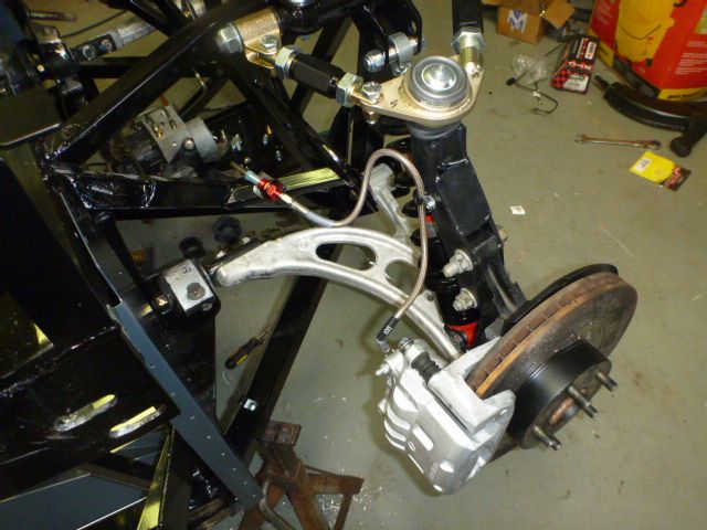
    I made up some 1/4 spacers to move the other bushing arm up over the bracket, just wouldn't work otherwise... I think Factory 5 has a frame jig issue...
    here is what I sent to them...

    After playing around a bit... I’ve determined that Factory 5’s frame jig is off...

    Left side, the upper bracket is too low and forward for the rear aluminum LCA bushing mount. The manual indicates that the bushing should go under the top mount. It can’t as it is about 1/16 – 1/8 inch too low. It is also too far forward, even if it was the right height putting it there would not allow the front LCA pivot to fit into the frame tabs. See 1st attached photo

    My solution: I am making up some nice 1/4 inch this spacers that match the footprint of the bushing to position it above the top bracket. This does move the rear pivot up 1/4 inch. See 2nd attached photo

    The right side has a different issue, the bracket is at the correct height, see the 3rd photo, however the position of the upper and lower brackets result in the holes not being able to be aligned. See photo 4

    My solution, same as the other side, use a 1/4 spacer. See photo 5 Note based on how you need to deflect the bushing on the left side it is the lower bracket that is off a bit causing the bolt hole misalignment.

    The bushing must go under by design to allow using the shorter wagon control arms, some customers will need to be more creative to resolve their issue, most likely with cutting and welding a nice powder coated frame.

    Thoughts?

    rightafter.PNGrighthole.PNGrightbushing.PNGleftafter.PNGleftbushing.PNG

    note the photos were made with 1/4 chunks of AL to prove concept, I now have some in my hands made on a bridgeport, mnatching the bushing's footprint that will look nice. If you just bolt them down on the top of the brackets you will bend and distort the bushing... you can see that on page 79 of the manual, when the busghing is shown on the top (even though they earlier show it on the bottom) you can see it sits on an angle...

    sorry the photos are not in order...

  21. #61
    818 builder metalmaker12's Avatar
    Join Date
    Mar 2012
    Location
    Exeter R.I
    Posts
    2,834
    Post Thanks / Like
    Blog Entries
    1
    I don't see the need, get to fit and bolt it in dan

  22. #62
    Mechie3's Avatar
    Join Date
    May 2012
    Location
    Indianapolis
    Posts
    5,174
    Post Thanks / Like
    What arm? Steel or Aluminum?
    Zero Decibel Motorsports
    Check out my new website!
    www.zerodecibelmotorsports.com
    www.facebook.com/zero.decibel.motorsports

  23. #63
    Senior Member RM1SepEx's Avatar
    Join Date
    Jul 2011
    Location
    Freeport, ME
    Posts
    3,801
    Post Thanks / Like
    if you have the shorter arms you have to cut and grind, you can't slide the bushing in farther to the other hole. That is a shame on a freshly powder coated frame. I wouldn't be happy if it was me. That's why they were designed to go under. We have also slightly modified the geometry, I'd have to review my suspension design books again to figure out exactly what, I just don't feel it's a big deal for us. It needs to be fixed so future people don't have the issue and have to run around to make spacers or just stress them because the don't line up! Some people won't find it as easy to make spacers as it is for us...

    we did sign up early to be ginea pigs!
    Just my engineering background coming out, I want it to be right!

  24. #64
    Mechie3's Avatar
    Join Date
    May 2012
    Location
    Indianapolis
    Posts
    5,174
    Post Thanks / Like
    Wayne bolted his on top. On a stock wrx, if you remove the knuckle the arm doesnt drop down. If you push it down it has a lot of resistance and springs back up because the bushing is binding.

    Zero Decibel Motorsports
    Check out my new website!
    www.zerodecibelmotorsports.com
    www.facebook.com/zero.decibel.motorsports

  25. #65
    818 builder metalmaker12's Avatar
    Join Date
    Mar 2012
    Location
    Exeter R.I
    Posts
    2,834
    Post Thanks / Like
    Blog Entries
    1
    Quote Originally Posted by Mechie3 View Post
    What arm? Steel or Aluminum?
    Aluminum, I will post mine, there bolted in like Wayne's

  26. #66
    Senior Member RM1SepEx's Avatar
    Join Date
    Jul 2011
    Location
    Freeport, ME
    Posts
    3,801
    Post Thanks / Like
    Mine are aluminum too and I had to bolt them on the top. As far as I can tell every existing 818 build has them on the top, yet the cad drawings and technical directions along with the dual use of the brackets demands that the design have them under. You can not mount the bushings over the outer holes for shorter arms on the top without some serious cutting.

  27. #67
    818 builder metalmaker12's Avatar
    Join Date
    Mar 2012
    Location
    Exeter R.I
    Posts
    2,834
    Post Thanks / Like
    Blog Entries
    1
    Oh the directions, yea I don't use them much, but yea you have to mount on top, as far as I can see.
    Here my pics, you can see on the right arm I cut the thread down to clear the panel
    photo-87.JPGphoto-86.JPGphoto-83.JPGphoto-84.JPG

  28. #68
    Senior Member RM1SepEx's Avatar
    Join Date
    Jul 2011
    Location
    Freeport, ME
    Posts
    3,801
    Post Thanks / Like
    Aluminum or steel does not matter, tho mine are aluminum, they are known to be interchangeable. The bushings vs the bracket is what matters... Factory 5 designed them to go in between the two brackets. Look at the cad drawing on page 71. In my world the engineer's drawing is the bible. Your parts should be oriented and positioned as they are in that drawing. I don't think Jim drew it that way with no purpose. If it sits on top you can not use the outer holes for shorter arms.

    one page 79 it states: The rear of the control arm bolts to the top of the bottom bracket and the bottom of the top bracket. The inner set of holes is for the WRX sedan arms and the outer is for the 2.5RS and Wagon.

    Any yes EVERY photo that I can find has them on top... even the one right above this statement.

    Take the bushing and put a bolt in one end, finger tight so that you can rotate it, your choice which one and orientation. If I do that on my chassis the holes never line up... something is amiss...

    I analyzed the crap out of this issue with another engineering friend Sunday...

    Metalmaker... I can't use the inner steel washers on the pivot shaft, they are not shown in the drawings and my arms won't fit if I try to use them.
    Last edited by RM1SepEx; 08-06-2013 at 09:35 AM.

  29. #69
    818 builder metalmaker12's Avatar
    Join Date
    Mar 2012
    Location
    Exeter R.I
    Posts
    2,834
    Post Thanks / Like
    Blog Entries
    1
    What inner steel bushings?, I am just kidding I have used the manual along the way, but I have made changes as I have gone forward

  30. #70
    fasterer and furiouser longislandwrx's Avatar
    Join Date
    Aug 2012
    Location
    Long Island
    Posts
    2,540
    Post Thanks / Like
    Blog Entries
    6
    Will this affect those doing the race height install? they both go under at that point right? Spacers for both?
    A well stocked beverage fridge is the key to any successful project.

  31. #71
    Senior Member RM1SepEx's Avatar
    Join Date
    Jul 2011
    Location
    Freeport, ME
    Posts
    3,801
    Post Thanks / Like
    Quote Originally Posted by metalmaker12 View Post
    What inner steel bushings?, I am just kidding I have used the manual along the way, but I have made changes as I have gone forward
    oops, brain fart... washers at the bushing washer, rubber washer with weird blocked face, bushing, rubber with blocked face, washer, nut.

    I can't use the inside washer and it isn't shown on any drawings or photos... It drives my A arm too far forward to fit in the other end's brackets

    I'm trying to work w/factory five re this issue.

  32. #72
    Senior Member
    Join Date
    Mar 2011
    Location
    Houston
    Posts
    477
    Post Thanks / Like
    I don't know if the following information from an old post of mine is pertinent here or not. Pardon me if it isn't!

    Anyway I just want to be sure that as sides are being swapped everyone is aware of this. Let me know if I'm wrong.

    fred


    The nuts were tight, but not a problem. The bushings were tight on their spindles, but not a problem either.
    As you see in the photographs the spindles are stepped.

    Spindle
    Click image for larger version.

    Spindle.jpg


    So you cannot just take say the RH bushing assembly and reverse it for 818 use.
    You have to swap the bushing assembly from the original LH LCA to the RH LCA....and visa versa. No problem since you have them both loose anyway.

    WRX configuration
    Click image for larger version.
    WRX Configuration.jpg


    818 Configuration
    Click image for larger version.

    818 Configuration.jpg

  33. #73
    Senior Member RM1SepEx's Avatar
    Join Date
    Jul 2011
    Location
    Freeport, ME
    Posts
    3,801
    Post Thanks / Like
    I just got off the phone with Tony Zullo:

    LCA mount issue

    they need to fit UNDER the top bracket for correct suspension geometry, spacers and putting it on top will work but isn't as desirable. Putting them on top with no spacer distorts the aluminum LCA bushing and is DANGEROUS as over stressing aluminum results in stress failures.

    So on my right side I need to simply bolt it up and align the bracket with no twisting stress and redrill the bushing. Correct bushing orientation is shown here and I've marked the bushing underneath. I'll put it on the milling machine and make the bolt hole an odd shape to fit. Right now it is off by about 1/2 the bolt. I've shaded the top so you can see where my hole lines up.
    I apologize for the poor photos, I set lower res to avoid issues uploading

    On my left side it is more complicated. First I need to remove about 1/2 inch of the vertical portion of the upper LCA mount. I've pointed to it with my finger in the second photo. This will allow the other end to align with the frames forward LCA mmounts. They changed the parts today, so I'm pretty sure any frame after this date won't have that issue. Next I need to jury rig a system to use a jack to spread the bracket so my mount will slide in. Again I'll have to "adjust" the hole either in the frame mount or the aluminum LCA bushing so that it aligns w/o stress.
    Attached Images Attached Images

  34. #74
    Mechie3's Avatar
    Join Date
    May 2012
    Location
    Indianapolis
    Posts
    5,174
    Post Thanks / Like
    Doh.
    Zero Decibel Motorsports
    Check out my new website!
    www.zerodecibelmotorsports.com
    www.facebook.com/zero.decibel.motorsports

  35. #75
    Senior Member RM1SepEx's Avatar
    Join Date
    Jul 2011
    Location
    Freeport, ME
    Posts
    3,801
    Post Thanks / Like
    we had so much conflicting information... :-) Mine will be correct and installed tomorrow... finished my black firewall this afternoon, looks sweet, so many places where you need to seal holes etc, the black on black works great. I'm using clear dow 50 year contractor grade everywhere else

  36. #76
    Senior Member
    Join Date
    Feb 2011
    Posts
    607
    Post Thanks / Like
    RM1SepEx. Are you going to cut that lip that hangs down on the firewall side of the top bracket? I think I will need to trim that down and drill some more holes in the brackets however, this will likely create one large hole. Are there an issues not having a perfect size bolt hole? I would think that as long as it's torqued down it should be fine.

    Are you going to drill into the bushing or chassis bracket?

  37. #77
    818 builder metalmaker12's Avatar
    Join Date
    Mar 2012
    Location
    Exeter R.I
    Posts
    2,834
    Post Thanks / Like
    Blog Entries
    1
    Quote Originally Posted by RM1SepEx View Post
    we had so much conflicting information... :-) Mine will be correct and installed tomorrow... finished my black firewall this afternoon, looks sweet, so many places where you need to seal holes etc, the black on black works great. I'm using clear dow 50 year contractor grade everywhere else
    Thanks for the research, I guess time to fix my arms

  38. #78
    Senior Member RM1SepEx's Avatar
    Join Date
    Jul 2011
    Location
    Freeport, ME
    Posts
    3,801
    Post Thanks / Like
    Quote Originally Posted by GUNS View Post
    RM1SepEx. Are you going to cut that lip that hangs down on the firewall side of the top bracket? I think I will need to trim that down and drill some more holes in the brackets however, this will likely create one large hole. Are there an issues not having a perfect size bolt hole? I would think that as long as it's torqued down it should be fine.

    Are you going to drill into the bushing or chassis bracket?
    One the right side I'm going to use a mill to make the hole in the bushing "fit" the bolt as closely as possible. I may jig up something to "repair" the hole... either JB weld or actually welding in the hole come to mind

    On the left side until I can actually see where the hole falls, I'm not sure. I have some little 4.5 cut off blades for my small grinder to cut the lip back 1/2 inch. According to F5 all new frames will have this mod. I'm not sure what this means, I got mine last week and it is Chassis # 17. I assume that they would fix anything not shipped. Once I can get it to line up I'll decide what to drill. The real PITA is getting the bracket up by between 1/8 and 3/16 so that the bushing actually fits between the brackets. I may have to make up something to brace the frame and bend that bracket w/o damaging the PC or bending something else! If it wasn't PC I could employ my favorite heat wrench.... :-)

    Dan

  39. #79
    818 builder metalmaker12's Avatar
    Join Date
    Mar 2012
    Location
    Exeter R.I
    Posts
    2,834
    Post Thanks / Like
    Blog Entries
    1
    I am going to fit my set in later tonightor tomorrow after work

  40. #80
    Senior Member
    Join Date
    Apr 2012
    Location
    Nepa
    Posts
    685
    Post Thanks / Like
    I guess every body has had this problem? I don't remember Erik, Wayne mention it. But maybe I missed it?

Page 2 of 34 FirstFirst 123412 ... LastLast

Posting Permissions

  • You may not post new threads
  • You may not post replies
  • You may not post attachments
  • You may not edit your posts
  •  

Stewart Transport

Visit our community sponsor