-
In the Interior Aluminum section of the manual (pgs. 136-138) you need to mount the dead pedal boxes before riveting the cockpit side panels. Although the dead pedals are shown in the photos, there is no mention of them in the instructions. Also note that the current panels have a passage hole for the cooling tubes. The pictures do not show this.
-
Senior Member

Boyd Tank Sender Fix
If you have a Boyd fuel tank the sender may need to be reversed so it reads about 90 ohm resistance when empty. If yours reads low (0 - 10) it needs to be reversed.
First, mark the round top of the sender so you can re-mount it in the same position. Unscrew the round top and lift the sender assembly out. See this photo and loosen the pivot screw and then re-insert the float rod on the other side, tighten screw. Next, loosen the nut at center of the top and rotate the top 180 degrees and re-tighten. Re-install with your mark in the same position so float does not hit the wall of the tank. Sender float fix.jpg
818S/C : Chassis #25 with 06 WRX 2.5 turbo, ABS, cruise, PS, A/C, Apple CarPlay, rear camera, power windows & locks, leather & other complexities. Sold 10/19 with 5,800 miles.
Mk3 Roadster #6228 4.6L, T45, IRS, PS, PB, ABS, Cruise, Koni's, 17" Halibrands, red w/ silver - 9K miles then sold @ Barrett-Jackson Jan 2011 (got back cash spent).
-
Transmission Fluid Level
Sometimes, the dipstick in the Subaru transmission can give you a false reading. After you FULLY drain your transmission, ensure you fill it with 3.5 liters (3.7 quarts) of the appropriate GL-5 75W-90 gear oil, regardless of what your dipstick tells you.
818S - #67 (SOLD IT!)
Delivered: 18 November 2013
Go Karted: 29 December 2013
Titled/Registered: 28 March 2014
Finished: NEVER!
341 hp @ 4844 RPM / 389 tq @ 3717 RPM
-
To set ride height for torquing the suspension bushings/mounts, you do not need any particular weight at all.
1. Mount your wheels with about 10 psi inflation pressure.
2. Make 4.5" or 4.75" (or whatever your target clearance number is) spacer blocks out of lumber and set them under the chassis at all four corners.
3. Adjust the spring pre load collars to absolutely no load at all.
With the low pressure in the tires your suspension links will all be very close to ride height now.
4. Torque up all mounting hardware.
And you are done.
Later you merely adjust the spring pre-loads to get the car to ride height. As you add weight you tighten the collars to get the chassis up to ride height, and the suspension components to their "neutral" condition.
-
Post Thanks / Like - 1 Thanks, 0 Likes
-
Senior Member

For all the bolts you plan on taking on and off throughout the build, buy standard nuts for quick mock and up and removal. Nylon lock nuts only take more time. Make sure to go over car on final approach and replace with intended lock-nuts.
For a cheap dolly system, Harbor Freight has wooden wheel dollies that are $15 each and can hold 2000lbs each. Simply put a cinder block with a wooden 4x6 on top at each corner for an easy, moveable system you can wheel around the garage. I've reused mine many times for different cars. More flexible than a fixed dolly that gets used once and dismantled.
To remove Gorilla tape residue, simply ball a new piece up and dab and twist it on on the body for quick pick up. A little hair dryer action helps even more. Cleaner and faster than goo-gone.
For fiberglass in the skin, again use gorilla tape and wrap it inside out around your hand and dab on your forearms and hands to pull out fiberglass splinters.
Spring-loaded, rubber-tipped clamps one of the easiest to use when clamping or holding body parts together or holding to the frame. Buy a bunch at harbor freight. I still don't have enough. Vice grip are strong but can take forever to adjust and get the right grip.
-
Senior Member

Drilling
As Dan mentioned and maybe others, for drilling the tip is oil, oil, oil, oil, oil. You can do a LOT of holes with one drill bit (if it's a good one) if you use enough oil. Dip the bit in engine oil once for every hole, or once per stop, meaning that if you stop drilling, dip again and continue.
Chances you will snap off a bit are minimal. It's the first time I was drilling in such tubing and I never broke a bit. After a while they wear off and tend to take more time to drill through, but the black oxide ones I got don't seem to snap. And with oil, NEVER they seize, nor come close to. Never.
Also, do not use a cord drill, it seems to drill forever!!!! A few holes took me 7-8mins each of non-stop drilling!!! Use a cordless drill, takes 30-90sec per hole. 14.4v is not much, you'll run out of power quickly. The 18v are much better and if you got 2 batteries, while one charges, you can do holes with the other and yes, the charging battery will fully charge before you drain your other Li-Ion battery. Hitachi green drill is quite great (Wayne Presley was using one on his thread). Choose high speed, torque it to 24 and fully pull the trigger until the hole is through. Put enough pressure, not too much, but enough. Just before puncture, you will hear, feel and see the end coming, lift off the throttle a bit to ensure you don't hit something when it drills through. Oil, oil, oil, oil, oil... I use new 15w50 Motul 300v Competition (left overs!).
Frank
818 chassis #181 powered by a '93 VW VR6 Turbo GT3582R
Go-karted Aug 5, 2016 - Then May 19+21, 2017
Tracked May 27/July 26, 2017
Build time before being driveable on Sep 27, 2019: over 6000h
Build Completed Winter 2021
-
Senior Member
Front lower shock mounts (alu LCAs)
When you drill through the 2006 alu LCAs, plz don't use a hand drill... it will take A LOT of time for nothing. This is what PART of the drilling by hand will do after many mins:
Attachment 29365
Instead, drill a bit the hole, to mark it well as a guide for the bit, and then use a press drill:
Attachment 29366Attachment 29367
And the result within a few mins only if not less than 60sec after you get the hang of it:
Attachment 29368
Frank
818 chassis #181 powered by a '93 VW VR6 Turbo GT3582R
Go-karted Aug 5, 2016 - Then May 19+21, 2017
Tracked May 27/July 26, 2017
Build time before being driveable on Sep 27, 2019: over 6000h
Build Completed Winter 2021
-
Senior Member

Frank any large hole can be drilled easily, even by hand, if you use a small pilot hole to start. ALWAYS use oil! As an example on the control arms, 1/8 to start, 3/16 next, then the final size. It will go rather quickly.
I did use a drill press but still started with a 1/8 pilot hole, the larger bits always work better with a pilot, bigger chips result.
Dan
818S #17 Picked up 8/1/13 First start 11/1/13 Go Kart 3/28/14
-
Post Thanks / Like - 1 Thanks, 0 Likes
-
818 builder


Originally Posted by
Frank818

When you drill through the 2006 alu LCAs, plz don't use a hand drill... it will take A LOT of time for nothing. This is what PART of the drilling by hand will do after many mins:
Attachment 29365
Instead, drill a bit the hole, to mark it well as a guide for the bit, and then use a press drill:
Attachment 29366Attachment 29367
And the result within a few mins only if not less than 60sec after you get the hang of it:
Attachment 29368
I used a hand drill with a vise no prob, it's aluminum man, just step drill it like Dan said and drill straight. Offcoasrsea press is better, but not always available. My press was right next to me, but I am primitive lol
-
Senior Member
Good points, I didn't think about starting with a smaller pilot hole and keep increasing.
Then the tips are it's better not to drill directly using the 10mm-13/32 bit, either 1- step drill or 2- press drill.
Frank
818 chassis #181 powered by a '93 VW VR6 Turbo GT3582R
Go-karted Aug 5, 2016 - Then May 19+21, 2017
Tracked May 27/July 26, 2017
Build time before being driveable on Sep 27, 2019: over 6000h
Build Completed Winter 2021
-
fix miss fit shock tower brace
When the shock tower cross bar won't fit, there is a quick fix. First your engine must be installed with the transmission. According to the Factory the chassis needs the weight to help the fit. Next line up as many of the bolts as possible, I got 3 of them with the upper right out by a few mm.
I tried a clamp to no avail, So I called my good friend Tom Kaufman ( The Fab Man ), and he took a 4-5 ft piece of 2X4 and placed it between the transmission and the cross bar and lifted up. this flexed the bar enough to put the last bolt in.
-
Member

Donor disassembly --
I recommend this product for loosening really rusty nuts and bolts, AeroKroil. It has some magic in it, dissolves the rust and lubricates. Aircraft mechanics use it routinely on the nuts that hold the exhaust manifolds to the heads - aircooled engines often run at 400 degrees F or more, and the nuts are rusty after a few years.
kroil.jpg
Also, I used this 3/8" air ratchet continuously as I took the donor apart. You can just rotate the handle to break the nut loose, then pull the trigger.
CP ratchet.jpg
It is from Chicago Pneumatic (which should be China Pneumatic, but it has served me well for many years).
john
-
Member
Deburring aluminum
When I have lots of holes to de burr (I just finished the belly skins), I use this tool...
deburring tool.jpg
It is an old Milwaukee screw driver, it turns very slowly, but easier than by hand. You can buy the hex adapter in many places.
Have fun!
-
Senior Member

Don't install the floor pan underneath the seats until you have figured out your seat mounting and seatbelt anchor points. Also if you are using a wagon donor for seat belts and/or a Boyd tank you may want to hold of on the rear side cockpit aluminum. It is easer to modify the pieces to cover the seatbelt hole and gap created by using the Boyd tank before they are riveted in place.
-
PLATNUM Supporting Member


If you ended up with a very rusty donor try using this needle scaler from HF. I worked well for me on suspension stuff and was only 20 bucks on sale.
IMG_0526.JPG
-
A heads up: If you have "dieted" the Daytime Running Lights system from your Subie donor, you have to jumper two wires at the Headlight relay - the Yellow/Green and the Yellow/Red. Otherwise the DRL relay is still operative and you will not have fully bright headlights.
-
Administrator


Here's how I mount the doors after mounting sidepods, rear panel, and engine cover.
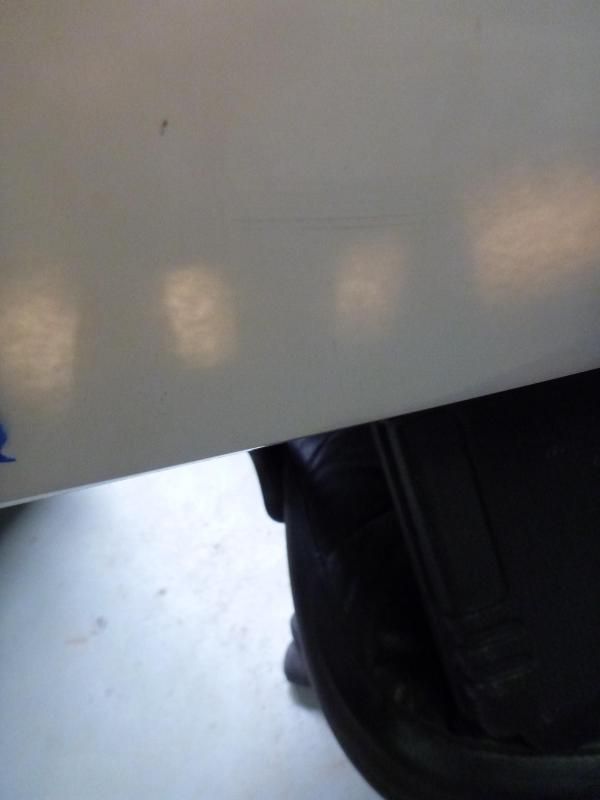
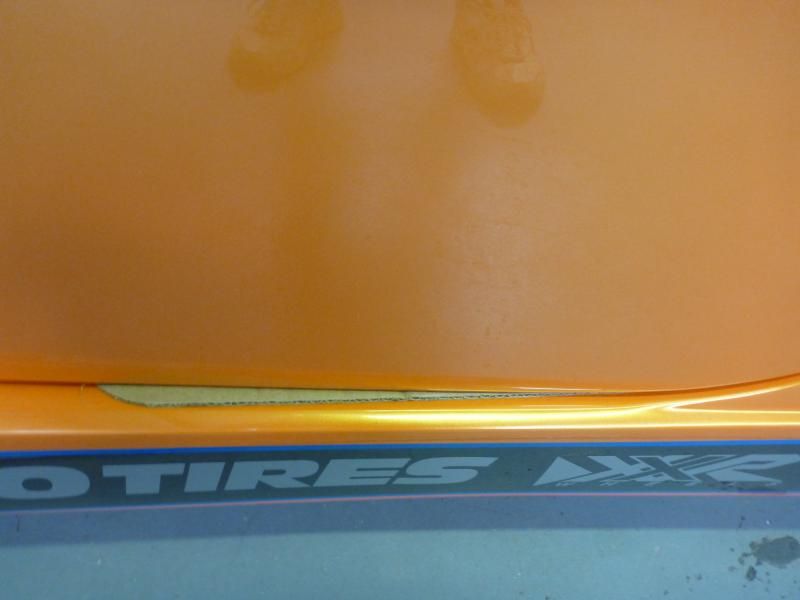
I mount the striker support up against he body, snug the bolts in the middle of the slots. Hold a bright light behind the bracket so you can see through the fiberglass and drill the holes in the middle of the slots.
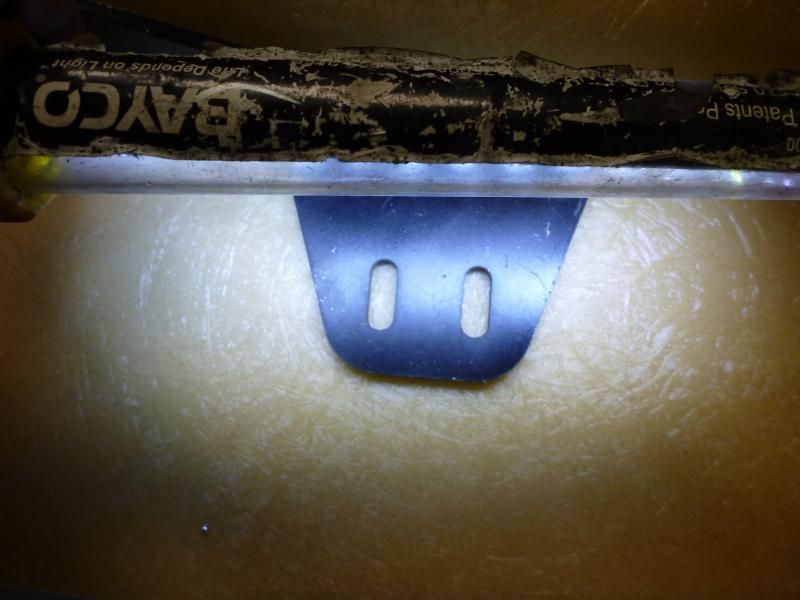
you can see the print through in this pic.
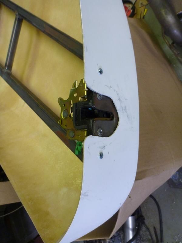
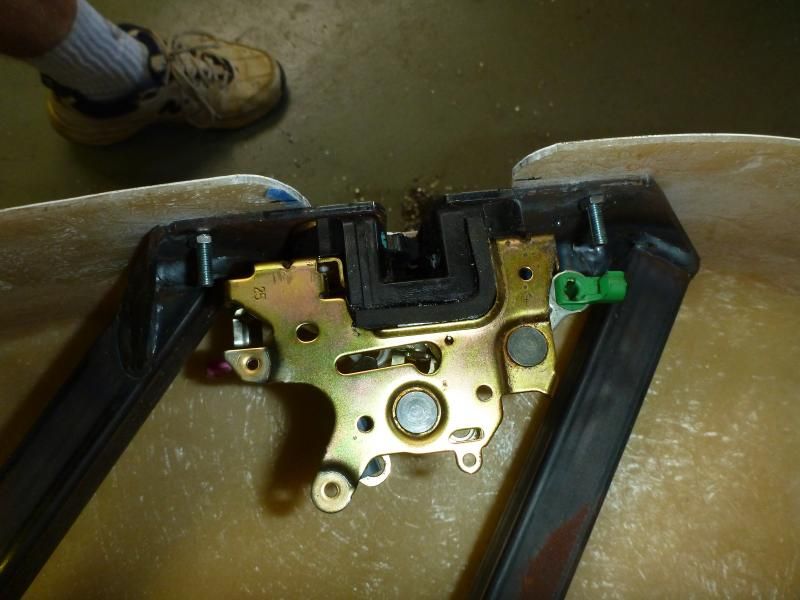
I mount the latches directly to the frame and countersink the screws. Latch the door frame to the striker and mount the hinges. Adjust the height of the front of the door frame to .250" above the sidepod, then tighten all hinge bolts. The door frame should now swing open and closed easily.
You can see 2 out of the 3 bolts holding the latch on in this pic.
Trim lower front corner off the door skin so the door can swing without the skin hitting the sidepod.
Now put a piece of masking tape along the edge of the door skin where the striker will go. Cut strips of regular cardboard and lay in the gap between the door and sidepod.
Door open, I use strips from the bottom of striker to the front of door (only one piece shown)
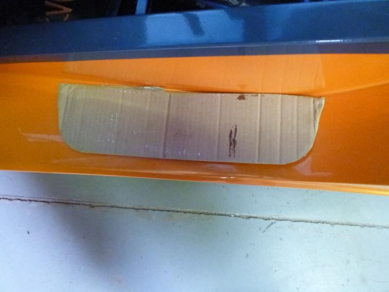
Door closed
Slide door skin into opening and tap on skin to mark on the masking tape where the door needs to be slotted for striker. Measure and mark door skin to allow for the complete striker to clear the skin. See pic 3 above.
Drill two 3/16" holes in the door frame as shown by the two 10-32 screws in the below pic.
Slide door skin back in on the cardboard shims, make the back of the door flush with the sidepods and drill top hole only. Install countersunk 10-32 screw in the top hole and tighten snug. Close door and recheck that the door skin is still flush with side pods and drill lower hole. Install countersunk 10-32 screw in the bottom hole and tighten snug.
On the top front of the door skin, drill the hole for the mirror mount so that edge of the skin overhangs the door frame by 3/16" and install a 10/32 screw. You will be using a different screw for final mounting, the 10-32 is to use until final mounting. Adjust front lower edge to the desired position and mark the lower frame to skin. Unbolt the 3/8" bolts and remove door leaving the hinges in place. Drill the lower hole in the skin and install the countersunk 10-32 screw, you will want a countersink due to the very limited clearance.
Install front door aluminum, mark and slot aluminum for 3/8" door bolts, install bulb seal on aluminum and final mount it to the door frame with rivets.
Install complete door back on the car with cardboard shims in place, the 3/8" bolts. Remove cardboard and fine tune hinges for smooth opening if necessary.
-
Specialty Tools (ST)
The Subaru Factory Manual frequently calls for Specialty Tools (ST). Here's a place that has them all divided into categories. Some of them make your life much easier!
https://subaru.service-solutions.com
"Good Judgement comes from Experience. Experience comes from Bad Judgement"
Owner: Colonel Red Racing
eBAy Store:
http://stores.ebay.com/colonelredracing
818R ICSCC SPM
2005 Subaru STI Race Car ICSCC ST and SPM
Palatov DP4 - ICSCC Sports Racer
-
Moonlight Performance


When installing the front firewall, make sure to install the pedal support bracket first. The manual shows it installed much later in the build process which would be impossible once the front firewall metal is in place.
Also, test fit the firewall panels before riveting them in. On mine, the pedal support bracket did not bolt-in quite flush. It was impossible to tell this until I put the sheet metal over it. By that point, the sheet metal that covered the bracket was in place so I was unable to adjust the fit of the bracket. The issue is that the part of the bracket that extends out for the clutch reservoir sticks out too far forward, preventing the sheet metal that covers that part of the bracket from making contact with the frame and leaving an ugly gap.
Will add a pic later.
-
Senior Member

Hindsight, this should be fixed in the manual. I figured it out and even talked to ffr to confirm that the plate should be the first piece fitted to the frame as step 1. I tend to jump around when I build so I cleco'd my panels and then started mocking up the brakes and steering when I discovered the problem. I've even mocked up my front suspension and I still haven't riveted the firewall. Once I have it all mocked up I will put it all together on the same day. For me it's easier to complete an area at once so I know it's all tight complete.
-
Moonlight Performance
The "I" version of the manual doesn't discuss the installation of the bracket. The "J" version does but it covers it in the wrong place (far too late). If there is "K" version of the manual where the bracket is shown in the correct installation order, I don't have it yet.
I didn't have time last night to take a pic and post an update of the problem area; hopefully I can get around to it tonight.
-
-
First, I painted my aluminum panels with Rust-O-Leum truck bedliner paint to cut down on sound. As it looks similar, I accidentally purchased the undercoating one time. When I ran out of bedliner, I used some undercoating paint on an interior panel that I will later cover in carpet. What I found is that I like the way the undercoating sprays out better, and I think I like the finish better. It is slightly different. Either way, if you go this route, I suggest getting a can of both and doing a comparison.
Second, I had tons of duct tape residue everywhere. On fiberglass Acetone works great and does NOT attack fiberglass. It quickly removes any residue you have. I did find out the hard way that the dash is not fiberglass and is not as big a fan of Acetone. Do NOT use Acetone on your dash.
I used Canola oil on both the dash and windshield surround. It took longer, but is less stressful.
The dash is now very shiny where I used the Acetone. I've blended it with some polish, but it will still need more work.
818S - #200
"To finish first, you must first finish"
"If the car feels like it is on rails, you are probably driving too slow." -Ross Bentley
"Never run out of real estate, ideas and traction at the same time."
-
BTW, I've found that the best thing to use to remove duct tape residue is some fresh duct tape.
-
Senior Member
The 02-05 throttle assembly is very flimsy, dump the FFR bracket and mount the pedal directly to the fire wall. I cut a piece of 2 x 2 x 1/8 aluminum angle to reinforce the firewall where the pedal mounts. It is riveted to the frame tubing with 3/16 rivets. I also added an extra bolt through the firewall, stiffens it right up.
P1120313.JPG P1120314.JPG
Dan
818S #17 Picked up 8/1/13 First start 11/1/13 Go Kart 3/28/14
-
I would drill and fit a majority of the front splash guards and subframe sheet metal before adding suspension. Don't rivet it in place yet, but get the holes made. It would have been much easier to drill some of the holes without the suspension blocking access.
-
Senior Member

Originally Posted by
Jaime
BTW, I've found that the best thing to use to remove duct tape residue is some fresh duct tape.
The one I've seen from working in boat yards for several years (back in the day) was 3M Adhesive Remover - fine for fiberglass, keep it away from paint though.
2011 Subaru Forester - the DD - uber rare 5spd manual
1990 Miata - Track Rat, autocrossing cheap POS - love it
2018 Factory 5 Racing 818 Hardtop Coupe - preapproved by the wife
-
Senior Member

Originally Posted by
Mechie3
I would drill and fit a majority of the front splash guards and subframe sheet metal before adding suspension. Don't rivet it in place yet, but get the holes made. It would have been much easier to drill some of the holes without the suspension blocking access.
Seems you would want the body panels to be on before mounting the splash panel in the front
Tony Nadalin
2018 SOVREN Big Bore Champion
2015 SCCA Oregon Region VP3 Champion
2012 ICSCC ITE Class Champion
FFR MkII Challenge Car, Spec Racer, Street Legal, SCCA, ICSCC and NASA Racing
818R Build in progress
-
That's the one panel I didn't fit, was the one in front of the wheel. The three that go around the radiator subframe, the one in front of the door, and the two that fit on the frame behind the wheel don't need the body in place. It's also much easier with the fenders removed.
-
PLATNUM Supporting Member
When installing your gas cap try this tip. First lube the inside of the hose and slip it on the tube just sticking out of the body a little bit. Then mark it with a silver sharpie. Cut along that line for a perfect fit when cap is installed on body. Do not forget your ground strap. I hope this is a help to some. Enjoy the build.
IMG_0908.JPGIMG_0909.JPGIMG_0910.JPG
-
Where is the ground strap mounted.
-
Senior Member

from the nut (pinched between nut and body) to the frame. This will ground the gas cap so you don't get a static spark between it and the nozzle when you go to fill up.
-
Member

Originally Posted by
billjr212
from the nut (pinched between nut and body) to the frame. This will ground the gas cap so you don't get a static spark between it and the nozzle when you go to fill up.
Thanks! This is really a key tip... Sounds stupidly obvious now that I know, but could've been something I and other novices would overlook. I did a quick look at the manual last night and didn't see any mention of grounding the gas cap.... Seem like a pretty critical safety step worth including!
-
And - I just discovered that in mounting the two panels on the frame inside the wheel well I had to remove some brake lines etc. These could have been more easily installed before other parts.
-
PLATNUM Supporting Member
Here is a tip that Huegenics, my paint shop passed on to me. When you are first mocking up your door for fit and gap, take time to do this when you are satisfied with the result. Drill 2 1/8" holes in each hinge to the door frame. This will allow you to put the hinges back on in the exact same place after fitting the aluminum front piece. You could even do this from the hinge to the frame if you want. You must take the door apart a few times as per manual instructions and IMO this is a great time saver. The photos show what I mean after I installed the aluminum. But I did it before and then drilled the aluminum to the holes and slots. You can use 2 -1/8" drill bits or I use 1/8" rod cut in 2" long pieces to realign every thing back.
IMG_0921.JPGIMG_0922.JPGIMG_0923.JPG
-
Replicating Mock up fitments
Great tip for the doors. It also can apply to the Windshield fitment. Once you have the windshield positioned as required, drill two 1/8 holes in both side braces so you can replicated it when you do your reassembly. It also permits you to install the glass with the windshield frame out of the car. This made it easier to install the glass while the frame was laying flat. For final assembly, realign your mocked up 1/8" holes and tighten your big bolt and you will be "right on."
-
Senior Member
Originally Posted by
wallace18
Here is a tip that Huegenics, my paint shop passed on to me. When you are first mocking up your door for fit and gap, take time to do this when you are satisfied with the result. Drill 2 1/8" holes in each hinge to the door frame. This will allow you to put the hinges back on in the exact same place after fitting the aluminum front piece. You could even do this from the hinge to the frame if you want. You must take the door apart a few times as per manual instructions and IMO this is a great time saver. The photos show what I mean after I installed the aluminum. But I did it before and then drilled the aluminum to the holes and slots. You can use 2 -1/8" drill bits or I use 1/8" rod cut in 2" long pieces to realign every thing back.
IMG_0921.JPGIMG_0922.JPGIMG_0923.JPG
use a 1/8 roll pin, spring steel easy to punch in and pull out with vice grips
Dan
818S #17 Picked up 8/1/13 First start 11/1/13 Go Kart 3/28/14
-
If installing a Wilwood pedal box to gain some legroom and get the pedal height to what I wanted in relation to the throttle pedal I shortened the Brake and Clutch master cylinder rods 1/2 inch. The Clutch pedal will bottom out on the clevis, I ground a small amount of material off the bottom of the clevis and the pedal to get the throw needed. This allowed the pedals to be moved 2.5" closer to the firewall and maintain 5.5" of travel.
-
I just finished my 818s. Being this is my first kit this is what I learned.
1) harbor freight air Rivetter. I had one my entire kit so I done know the pain of doing it by hand but the air tool was awesome.
2) as soon as you get the kit figure out where every piece of aluminum goes. There are 2 pieces that I wasn't sure where they went, they are apart of the front splash guards. And not I've got brake lines running through where these panels go. To be fair I ran my brakes in the same place at the manual. Which has almost no mention of these parts.
3) definitely agree with the engine install info above, took my almost 4 hours of wiggling to get my engine in with the exhaust manifold still on.
4)I separated all the nuts and bolts into gallon bags by size, seemed to work out good.
5) when drilling for 3/16 rivets use the next size larger drill bit, makes it so there's no fighting to get the rivets in. Not a big issue on the 1/8 rivets. Maybe it was just me.
6) Invest in a right angle drill, would have made a lot of the drilling easier. I also bought a Dremel, which I would same is a must have for getting the body to fit.
If I think of something else I'll post.
-
Senior Member

I just experienced having to backtrack last night due to the pedal box mounting plate not being attached. I had to drill out rivets and remove 2 panels many here have said. Wish I read this a week ago. Luckly I was able to reuse the holes I drilled in the aluminum. But still a PITA non the less...
On another note this thread edu-ma-cated me on what the firewall center aluminum is used for. 
Last edited by TrickyPete; 03-15-2015 at 12:14 PM.


 Thanks:
  Likes:


 Reply With Quote


