Forte's

Visit our community sponsor

Thanks Thanks:  0
Likes Likes:  0
Results 1 to 33 of 33

Thread: Started my wire diet.

  1. #1

    Join Date
    Feb 2011
    Location
    Norton, MA USA earth
    Posts
    3,348
    Post Thanks / Like

    Started my wire diet.

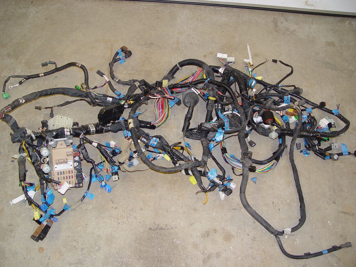
    Spent about 10 hours this weekend on my wire diet. Here is the before


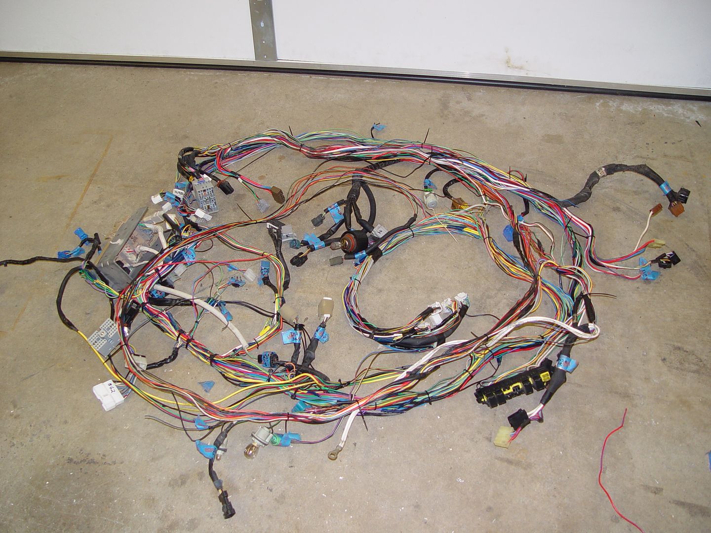
    and here is the after.


    and the trash


    This is just the first phase. I will now need to mount the harness in the car and see what needs to be moved, lengthened and shortened.

    Here is a quick list of what I removed.

    All air bag wiring
    all 4 door plugs and wiring
    air conditioning
    radio
    HVAC
    integrated module
    Secondary fan
    Brake level
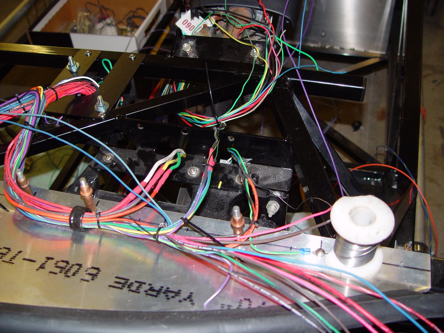
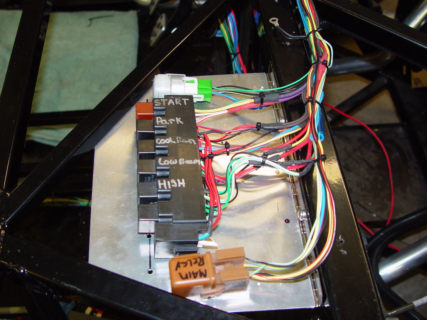
    washer plug
    Power windows
    Power locks
    Fog lights
    side marker lights
    ABS

    Maybe next weekend I can lay it in the car and work on it some more.
    Mike

  2. #2
    East Coast Speed Machines Erik W. Treves's Avatar
    Join Date
    Feb 2011
    Location
    Huntsville, Al
    Posts
    2,111
    Post Thanks / Like
    that looks fantastic!
    FFR 1879, Blown DSS 306,REDLINE management, VeryCoolParts Tuned 460RWHP

    FFR 818S, The Flash, Chassis #5, 2.0L, LSD, Electromotive TEC-S, VCP Tuned, 278RWHP 265 RWTQ

    FFR 6651, Green Lantern, 408W Crate, Hellion 66mm Turbo, JGS Waste gate / Blowoff valve, Tec-GT management, VCP Tuned, 575 RWHP, 690 RWTQ

    FFR 8335, Black Mamba, 289 FIA CSX 2001 tribute car, 347, 48 IDA webers, VCP Tuned, 311 RWHP 386 RWTQ, 3-link, Trigo's

    FFR 0004, Gen 3 , Hawk Coupe, Coyote twin turbo, 683 RWHP 559 RWTQ, IRS, VCP Tuned. "not too shabby"

    US ARMY Maintenance Test Pilot (CW4 Retired)

  3. #3
    cobra Handler skullandbones's Avatar
    Join Date
    Jul 2011
    Location
    Superstition Mtn foothills 5 miles west of Gold Canyon AZ
    Posts
    2,686
    Post Thanks / Like
    Blog Entries
    19
    That's pretty impressive Michael and not for the faint of heart! I know I tried once and gave up on it.

    Good luck on phase two,

    WEK.
    FFR MkIII 302 (ATK), EFI 75mm TB with custom box plenum chamber, 24# injectors, 4 tube BBK ceramic, cold air sys, alum flywheel, crane roller rockers, T5, Wilwood pedals, custom five link with Watt's link, 4 rotors, coil overs, power steering with Heidt valve, alum FFR rad, driver's crash bar mod, mini dead pedal mod, quick release steering wheel hub #6046

  4. #4
    Senior Member FFRSpec72's Avatar
    Join Date
    Feb 2011
    Location
    Kirkland, WA
    Posts
    2,255
    Post Thanks / Like
    It looks like you deleted connector F4. So that you do it right, I will send you my 02 harness and you can try again.

    it does look like you started with a small harness, as my 02 harness looks much larger and intimidating that your harness. As I laid mine out again today to looks.

    WP_20140126_001copy.jpg
    Attached Images Attached Images
    Last edited by FFRSpec72; 01-26-2014 at 11:21 PM.
    Tony Nadalin
    2018 SOVREN Big Bore Champion
    2015 SCCA Oregon Region VP3 Champion
    2012 ICSCC ITE Class Champion
    FFR MkII Challenge Car, Spec Racer, Street Legal, SCCA, ICSCC and NASA Racing
    818R Build in progress

  5. #5

    Join Date
    Feb 2011
    Location
    Norton, MA USA earth
    Posts
    3,348
    Post Thanks / Like
    What is connector F4? I am pretty sure I still have my O2 connector. My harness is a stock 02 The only thing not in the picture is the rear most harness. I accidently threw it out.
    Mike

  6. #6

    Join Date
    Feb 2011
    Location
    Norton, MA USA earth
    Posts
    3,348
    Post Thanks / Like
    My harness is a stock 02 The only thing not in the picture is the rear most harness. I accidently threw it out.
    Mike

  7. #7
    818 Builder
    Join Date
    Dec 2013
    Location
    Taunton, MA
    Posts
    71
    Post Thanks / Like
    Has anyone confirmed removal of the body integrated unit doesn't cause any issues with the car? From what I can find, it controls lights, gauges, ac, etc. I can live without a lot of the stuff it controls, but not knowing the details, I can't tell whether there are any needed gauges or lights that will be adversely affected.

  8. #8

    Join Date
    Feb 2011
    Location
    Norton, MA USA earth
    Posts
    3,348
    Post Thanks / Like
    Randy. It didn't look to me like it was needed. I have decided to go a different route after try to fit the dieted harness. I harvested everything needed to run the engine ad tossed the rest. I will use a painless harness to do the lights etc. I saved the steering column and gauge cluster plugs so I can integrate them. Stay tuned with more pictures.


    Mike

  9. #9

    Join Date
    Feb 2011
    Location
    Norton, MA USA earth
    Posts
    3,348
    Post Thanks / Like
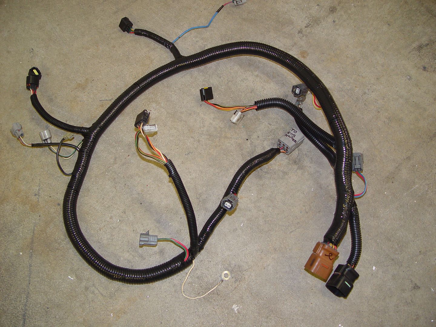
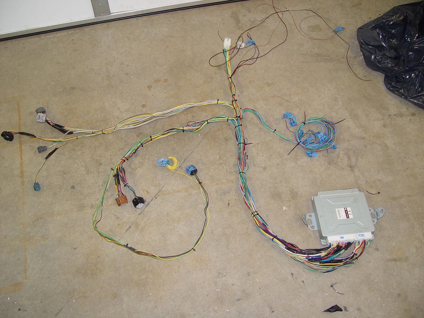
    Ok this is what is left. I deleted almost everything that was not needed to run the engine.


    This is the harness that actually runs through the engine. I removed a few wires and rerouted some others.


    This is whats left of the donor harness. The coiled wires above the ECU will also be eliminated once I know it runs without them Most of them are related to the fuel system. The rest will be done with a painless harness.
    Mike

    Here

  10. #10
    818 builder metalmaker12's Avatar
    Join Date
    Mar 2012
    Location
    Exeter R.I
    Posts
    2,834
    Post Thanks / Like
    Blog Entries
    1
    Cool, the only thing is the brake light will stay lite without plugged into the master resovoir. But nice diet. I should go back and take little more out, but I am lazy at this point cause it all works

  11. #11
    Senior Member flynntuna's Avatar
    Join Date
    Apr 2011
    Location
    San Diego Ca 92106
    Posts
    1,972
    Post Thanks / Like
    Forgive the noob question, but what about the connecting the gauges?

  12. #12
    Junior Member
    Join Date
    Jan 2014
    Posts
    9
    Post Thanks / Like
    What a nice setup M.E.! Keep us posted on the installation.

  13. #13

    Join Date
    Feb 2011
    Location
    Norton, MA USA earth
    Posts
    3,348
    Post Thanks / Like
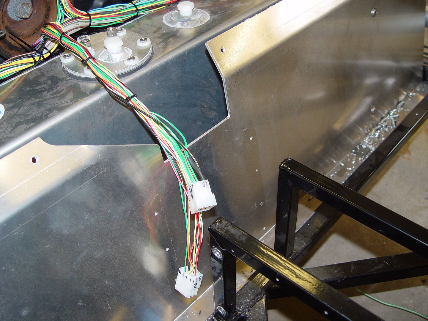
    Flynntuna. The gauges will be hooked up to the proper wires. These plugs below will go to the gauge pod, steering column and ignition switch.


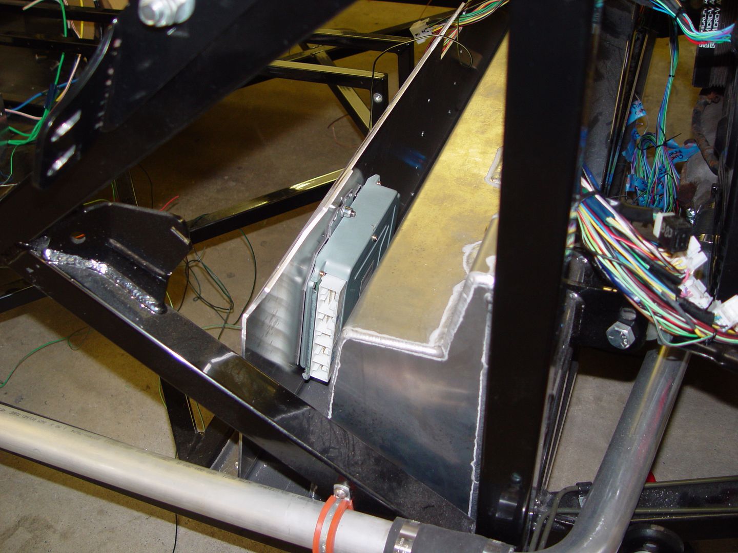
    Here is how I plan to run the harness unless someone sees an issue with this. I will call be covered once I prove it out.


    Computer mounted to the back side of the rear wall.


  14. #14

    Join Date
    Feb 2011
    Location
    Norton, MA USA earth
    Posts
    3,348
    Post Thanks / Like
    Chris. I think I can just cut power to the brake light int he pod.
    Mike

  15. #15
    818 builder metalmaker12's Avatar
    Join Date
    Mar 2012
    Location
    Exeter R.I
    Posts
    2,834
    Post Thanks / Like
    Blog Entries
    1
    Yea true, since your using a sepetate set of wires and you deleted what you did , that should do it. Nice diet, makes me want to break mine down more. A true veteran FFR builder at work!!
    Last edited by metalmaker12; 02-02-2014 at 04:37 PM.

  16. #16
    Senior Member Bob_n_Cincy's Avatar
    Join Date
    Sep 2012
    Location
    Cincinnati OH
    Posts
    3,904
    Post Thanks / Like
    Quote Originally Posted by michael everson View Post
    Ok this is what is left. I deleted almost everything that was not needed to run the engine.

    This is the harness that actually runs through the engine. I removed a few wires and rerouted some others.

    This is whats left of the donor harness. The coiled wires above the ECU will also be eliminated once I know it runs without them Most of them are related to the fuel system. The rest will be done with a painless harness.
    Mike

    Here
    Michael
    Great job,
    Your diet procedure is exactly what I'm doing also. I'm in the process of making the schematic for what I will be left with.
    I am going to put my ECU under the dash and run the wires with the coolant tubes.
    If I were you I would not put the ECU in front of the gas tank. Move the ECU up above the gas tank and move the fire wall back against the gas tank to give you more room in the cockpit.
    Bob

  17. #17
    Senior Member Doowop's Avatar
    Join Date
    Jan 2014
    Location
    Denver, CO
    Posts
    208
    Post Thanks / Like
    Nice!! any idea on weight difference?

  18. #18
    fasterer and furiouser longislandwrx's Avatar
    Join Date
    Aug 2012
    Location
    Long Island
    Posts
    2,540
    Post Thanks / Like
    Blog Entries
    6
    That looks awesome. Interested in seeing how it works out, using a painless kit for the chassis wiring seems much simpler than extending and shortening so many wires.
    A well stocked beverage fridge is the key to any successful project.

  19. #19

    Join Date
    Feb 2011
    Location
    Norton, MA USA earth
    Posts
    3,348
    Post Thanks / Like
    I hope to install the painless wiring this weekend. I can see any reason why it will not work. Just need the pin outs fo the steering column.
    Mike

  20. #20
    Mechie3's Avatar
    Join Date
    May 2012
    Location
    Indianapolis
    Posts
    5,174
    Post Thanks / Like
    Very nice. Makes me wish I had done the same and skipped all the fuse boxes.
    Zero Decibel Motorsports
    Check out my new website!
    www.zerodecibelmotorsports.com
    www.facebook.com/zero.decibel.motorsports

  21. #21
    fasterer and furiouser longislandwrx's Avatar
    Join Date
    Aug 2012
    Location
    Long Island
    Posts
    2,540
    Post Thanks / Like
    Blog Entries
    6
    are you wiring the fans from the ecu or just to a thermostat?


    also are you keeping the EBCS?
    Last edited by longislandwrx; 02-04-2014 at 10:44 AM.
    A well stocked beverage fridge is the key to any successful project.

  22. #22

    Join Date
    Feb 2011
    Location
    Norton, MA USA earth
    Posts
    3,348
    Post Thanks / Like
    I am hoping to trigger the fan through the ECU. Although I havent figured that out yet. What is the EBCS?

  23. #23
    Mechie3's Avatar
    Join Date
    May 2012
    Location
    Indianapolis
    Posts
    5,174
    Post Thanks / Like
    Electronic boost control solenoid.
    Zero Decibel Motorsports
    Check out my new website!
    www.zerodecibelmotorsports.com
    www.facebook.com/zero.decibel.motorsports

  24. #24

    Join Date
    Feb 2011
    Location
    Norton, MA USA earth
    Posts
    3,348
    Post Thanks / Like
    Hmm good question. First I have heard of it. What does it look like? I have a wastegate solenoid?
    Mike

  25. #25
    Mechie3's Avatar
    Join Date
    May 2012
    Location
    Indianapolis
    Posts
    5,174
    Post Thanks / Like
    Same thing.
    Zero Decibel Motorsports
    Check out my new website!
    www.zerodecibelmotorsports.com
    www.facebook.com/zero.decibel.motorsports

  26. #26

    Join Date
    Feb 2011
    Location
    Norton, MA USA earth
    Posts
    3,348
    Post Thanks / Like
    Ok. I am using it.

  27. #27
    Tazio Nuvolari wannabe Scargo's Avatar
    Join Date
    Nov 2013
    Location
    south-central CT
    Posts
    1,611
    Post Thanks / Like
    Quote Originally Posted by michael everson View Post
    Hmm good question. First I have heard of it. What does it look like? I have a wastegate solenoid?
    Mike
    An EBCS is usually recommended when you start fooling with boost. It was the first thing my tuner said to get (besides a Cobb Accessport).
    A Grimmspeed ECBS seems to be the most popular and it more accurately controls the boost than the stock solenoid. I've been running one for years.

  28. #28

    Join Date
    Feb 2011
    Location
    Norton, MA USA earth
    Posts
    3,348
    Post Thanks / Like
    I started routing the painless wiring harness today. I am starting with a 12 circuit system. I really think this is going to be an easy conversion. The wiring diagrams that a fellow member gave me, help a lot. The hardest part will be harvesting all the engine controls from the harness. Once you do that, the painless just takes the place of everything else.


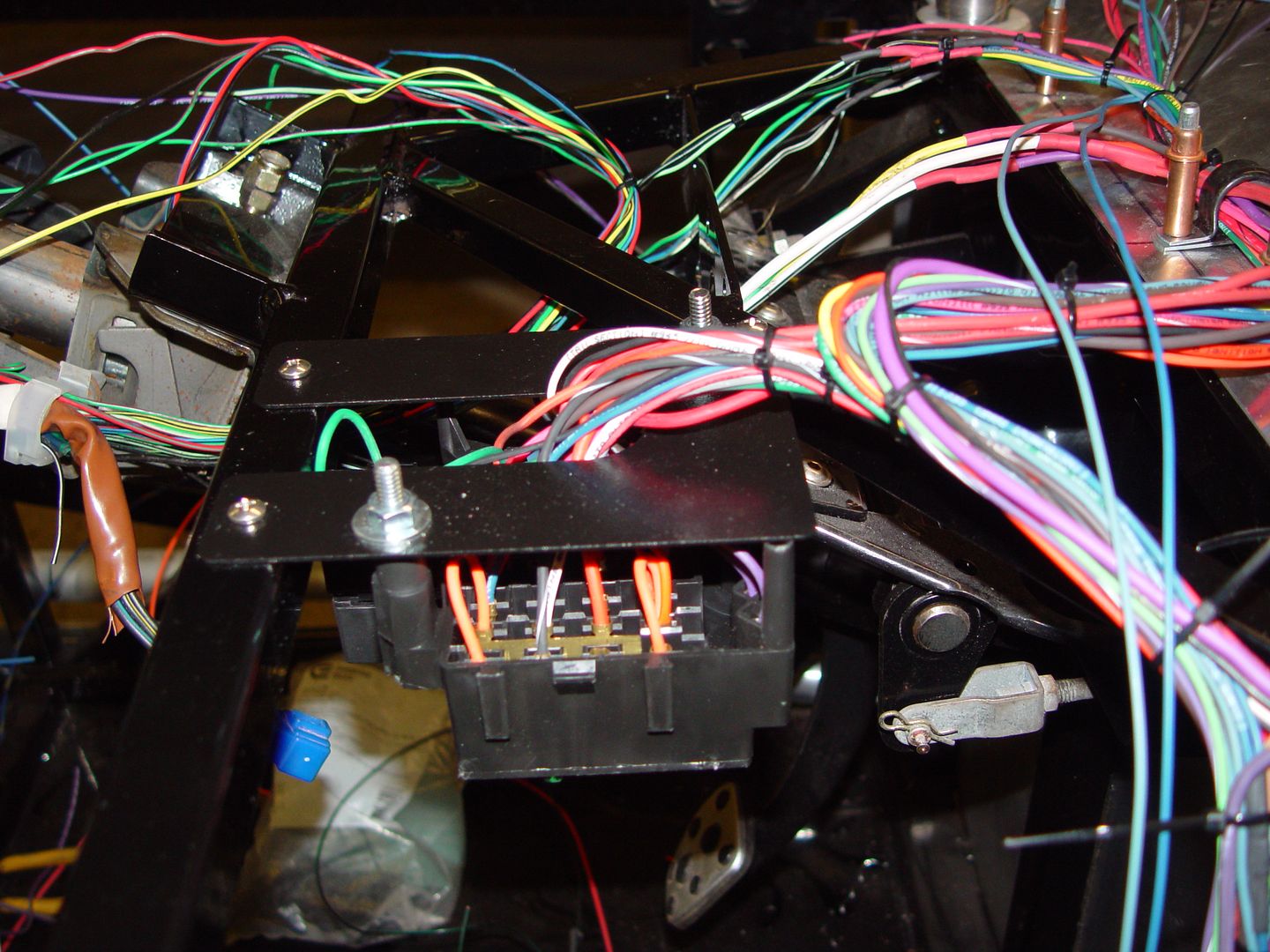
    I started by mounting the fuse box as shown in this picture. It should be fairly easy to get at it if needed.
    It is just to the right of the steering column but not obscured by the center console.


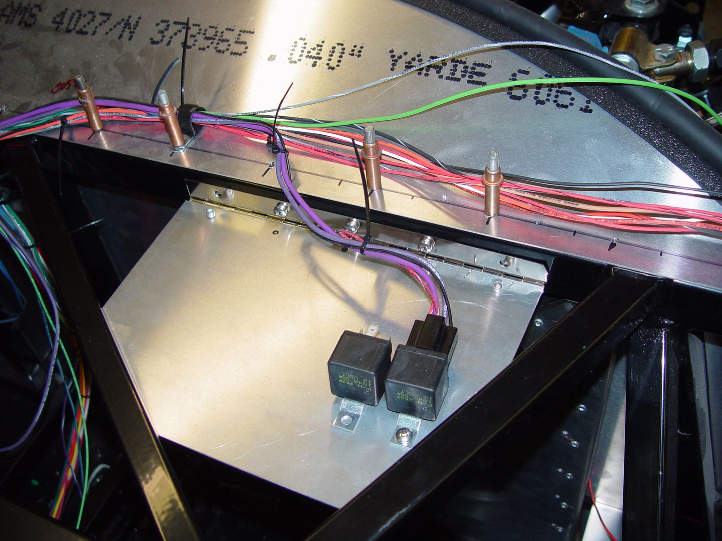
    I made up this hinged panel that will hold all the relays. There will be one for the fan, high beams, fuel pump, and starter. also the main relay that was used in the Subaru.


    Here is a shot of some of the connections to the steering column and ignition switch. I have the ignition switch and the directionals all wired up. Startre circuit too. All of this will be covered with conduit once it is proven out.
    Stay tuned for more pictures.

  29. #29

    Join Date
    Feb 2011
    Location
    Norton, MA USA earth
    Posts
    3,348
    Post Thanks / Like
    I decided it might be better to use the Subaru relay block instead of sourcing separate relays and wiring them in. Why reinvent the wheel? I think it will look much cleaner in the end.


    This is what the relays do.

    From top to bottom
    Fuel pump
    Starter enable
    parking lights
    Cooling fan
    Low beam
    high beam.
    Empty
    Main engine harness relay

    I wired the head light switch using only grounds. So the switch triggers the appropriate relay depending on switch position.
    Not sure if this is how it was done in the Subaru, but it made sense in this application.

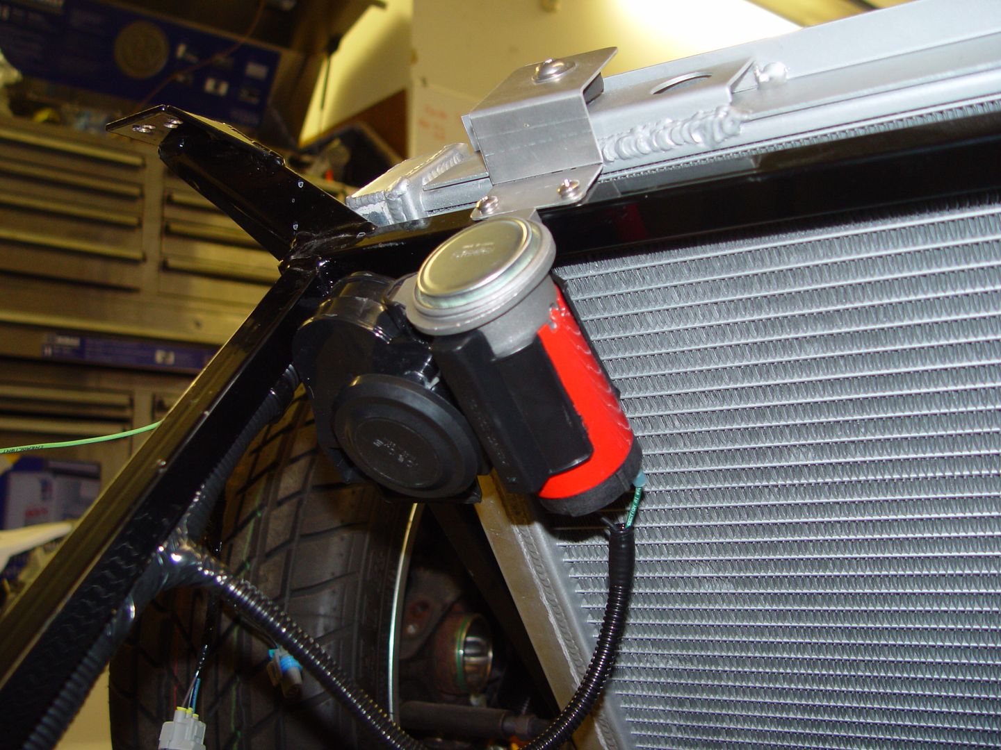
    Here is my compact electric air horn.
    These things are real loud.


  30. #30
    818 builder metalmaker12's Avatar
    Join Date
    Mar 2012
    Location
    Exeter R.I
    Posts
    2,834
    Post Thanks / Like
    Blog Entries
    1
    Nice work, and that is how the subaru headlights basically work
    Last edited by metalmaker12; 02-15-2014 at 05:49 PM.

  31. #31
    Senior Member FFRSpec72's Avatar
    Join Date
    Feb 2011
    Location
    Kirkland, WA
    Posts
    2,255
    Post Thanks / Like
    Quote Originally Posted by michael everson View Post
    Ok this is what is left. I deleted almost everything that was not needed to run the engine.
    So if I look at the wire diagrams is the first picture (the one that has be wrapped) the Front Harness and the second picture (with the ecm) the Bulkhead Wire Harness (in compartment and in engine) ? I gather you only dieted the Front Harness and Bulkhead Wire Harness (in compartment and in engien) ?
    Last edited by FFRSpec72; 02-19-2014 at 01:38 AM.
    Tony Nadalin
    2018 SOVREN Big Bore Champion
    2015 SCCA Oregon Region VP3 Champion
    2012 ICSCC ITE Class Champion
    FFR MkII Challenge Car, Spec Racer, Street Legal, SCCA, ICSCC and NASA Racing
    818R Build in progress

  32. #32
    Senior Member Pearldrummer7's Avatar
    Join Date
    Feb 2014
    Location
    Asheville, NC
    Posts
    1,230
    Post Thanks / Like
    Wow. This is beautiful! Weight savings? The space savings are great. What do you plan to cover them with? Also, where did you get these wiring diagrams?? I would love them for my 02.

  33. #33
    Senior Member Xusia's Avatar
    Join Date
    Oct 2011
    Location
    Eugene, OR, USA
    Posts
    2,343
    Post Thanks / Like
    PM Fate066.

Posting Permissions

  • You may not post new threads
  • You may not post replies
  • You may not post attachments
  • You may not edit your posts
  •  

Martin's Dent and Collision Shop

Visit our community sponsor