-
03-21-2016, 10:32 PM
#161
Senior Member


Originally Posted by
ThickCobra

Sorry for being late to the party on fuel line size and filter usage. Often when I'm browsing thru posts, I see something that I want to be certain about for my anniversary build. First the fuel line size. I have a Forte supplied Dart 351stroker (427) with a mild cam -450 hp. I have read a few postings on the fuel line size but want to be certain. I am running an engine mounted fuel pump with no return line. And, of course, no in-tank fuel pump. The kit comes with a 5/16" size fuel line which I have already run. Will I regret not switching to 3/8".
Second, I have read that installing the supplied ffr fuel filter, for my set up, between the fuel tank and mechanical pump is a no no as it could lead to fuel pump failer. Mike Forte tells me he installed an in line filter at the carburetor. Am I correct on this topic?
Originally Posted by
Jazzman
I am probably not the best expert on this topic, ThickCobra, but I will share what I have learned. I am going with the Coyote engine, and there seems to be consensus that the 5/16" lines are adequate for "mid range" builds. EdwardB (certainly an expert far beyond my own knowledge) is a proponent of the 3/8" lines and has used them on two builds. His current and previous build threads have a good discussion on the reasons he believes that the larger lines provide a larger margin of safety for higher horsepower installations. The reason for the concern about the in line filter has to do with unnecessary strain on the fuel pump leading to premature pump failure. I went with an in tank fuel pump, but a higher volume pump. I'm sorry I can't give you specific information about your setup.
Let me give a couple responses to this. I'm far from an expert. Several builds and the resultant experience, yes. But I'm learning as I go too. My first build, a Mk3 with a pretty strong 306 SBF, used the stock 5/16 FF lines. (See, I can use the parts that come with the kit. Sometimes...) It's a mechanical pump/carb setup, and certainly has never had a fuel delivery issue. Runs great, now with another owner. I spent a long time looking at multiple forums and data when planning my last Mk4 with the DART 347. Found everything from the 5/16 stock lines are fine to guys that went with 1/2 inch lines. (Really!) When all was said and done, 5/16 probably would have been OK, but 3/8 was probably safer. But the tipping point was I wanted to do SS lines, just because, and there was little/no difference in 5/16 versus 3/8 at that point buying the material, bending the lines, doing the installation, etc. Very similar rationale with the current Coyote built. The data shows 5/16 feed and 1/4 return flow enough fuel. But several pump and regulator instructions suggested using 3/8 lines for both, and again because I decided to use SS for the lines (I can't seem to get enough punishment) it was a no-brainer just to do them in 3/8. So in both cases, was 3/8 really needed? Maybe not. But it was what I wanted to do and eliminated any possibility of the lines being undersized. Needless to say, having to change them after the build is done would not be fun.
So those were the reasons behind what I did. I would be inclined to suggest 3/8 lines for a 351 based 427, but I can't say with data you would ever outrun the 5/16 lines. If you do a search for HP suggestions for various fuel line sizes, you will find the recommendations all over the map. Over on the other forum you will find some of that too. You're describing a pretty mild 427, probably even a bit less than the pretty strong 347 in my Mk4. But I personally would still lean towards the 3/8 inch lines. But then you've seen my rationale, so you can decide if that means anything to you.
What I can say with confidence though is for mechanical fuel pump systems, do not put the filter between the tank and the pump. That is only for EFI systems. For a mechanical fuel pump setup, the filter should be between the fuel pump and the carb. In both cases there should be a rough filter or screen on the pickup (or pump) in the tank.
Last edited by edwardb; 04-07-2016 at 07:31 AM.
Build 1: Mk3 Roadster #5125. Sold 11/08/2014.
Build 2: Mk4 Roadster #7750. Sold 04/10/2017.
Build Thread
Build 3: Mk4 Roadster 20th Anniversary #8674. Sold 09/07/2020.
Build Thread and
Video.
Build 4: Gen 3 Type 65 Coupe #59. Gen 3 Coyote. Legal 03/04/2020.
Build Thread and
Video
Build 5: 35 Hot Rod Truck #138. LS3 and 4L65E auto. Rcvd 01/05/2021. Legal 04/20/2023.
Build Thread. Sold 11/9/2023.
-
03-22-2016, 09:12 AM
#162
Not a waxer

Originally Posted by
edwardb
...What I can say with confidence though is for mechanical fuel pump systems, do not put the filter between the tank and the pump. That is only for EFI systems. For a mechanical fuel pump setup, the filter should be between the fuel pump and the carb. In both cases there should be a rough filter or screen on the pickup (or pump) in the tank.
Whether we're talking EFI or carb, electric pump or mechanical the filter needs to be on the pressurized side, note the suction side.
RE: fuel line size. Things are different for EFI vs carb. While it isn't an exact science you should be fine with 5/16". Think about it for a minute...the real bottleneck will be the carb's needle and seat. Do the math; the area of a 5/16" (.3125") line is .0767 square inches (pi X the radius squared). Holley's large "high flow" needle and seats are .150" which equates to .0176 square inches. Multiply that X2 for the primary and secondary circuits and the total is .0353 square inches; roughly half of the area of the fuel line. It's oversimplifying because pressure comes into play but even at that you need to think of an hourglass:

No matter how big the bowl is on the top you'll still only get so much sand through the neck.
Jeff
-
03-22-2016, 09:15 AM
#163
Man o man, thanks for the very important feedback. Like most, I don't relish the thought of do-overs. You have both given me a lot to think about. I had felt pretty confident about the filter positioning, but as I was about to do the final attachment of the rear deck panels, I thought I would hit the subject once more. And, yes, I have a screen on the pick up. Many thanks.
As for the line size, I am trying to accomplish this build with using as much of the FFR supplied parts and components as possible. I'm certain that on my next build, if there will be one, I'll probably go mod crazy. You guys know that as a first time builder, you usually have your hands full understanding the basics and becoming more comfortable with researching and reaching out for help. But for now, (1) as it appears I should be safe with 5/16" steel FFR supplied lines feeding my "mild" build and (2) as the kit comes with the pickup fitting for a 5/16" line, and (3) the Forte supplied mechanical pump accommodates a 5/16" line, I can save a bunch of money. Fingers crossed. Besides, I'll squirrel the savings away for the next build.
-
03-22-2016, 10:03 AM
#164
Senior Member
Originally Posted by
Jeff Kleiner
Whether we're talking EFI or carb, electric pump or mechanical the filter needs to be on the pressurized side, note the suction side. Jeff
That's the result of doing it like I described, just with fewer words. Thanks!
Build 1: Mk3 Roadster #5125. Sold 11/08/2014.
Build 2: Mk4 Roadster #7750. Sold 04/10/2017.
Build Thread
Build 3: Mk4 Roadster 20th Anniversary #8674. Sold 09/07/2020.
Build Thread and
Video.
Build 4: Gen 3 Type 65 Coupe #59. Gen 3 Coyote. Legal 03/04/2020.
Build Thread and
Video
Build 5: 35 Hot Rod Truck #138. LS3 and 4L65E auto. Rcvd 01/05/2021. Legal 04/20/2023.
Build Thread. Sold 11/9/2023.
-
03-26-2016, 10:58 PM
#165


Clutch M/C, Wiring, Ebrakes, hoses, etc.
First, a big thumbs up for Mike Forte at Forte's Part Connection. On Thursday morning I ordered his hydraulic clutch kit, and lamented that I should have ordered it earlier in the week so I could have installed it this weekend. I was really surprised and impressed when the box arrived today, just two days later!. Thanks Mike! Great service.
Yesterday I got the rear brake lines laid in. I had to do it a bit differently than most due to the use of the rear battery box. I put the fixed attachment point on the angled down rod rather than the horizontal 2X3 square channel. It worked out nicely.

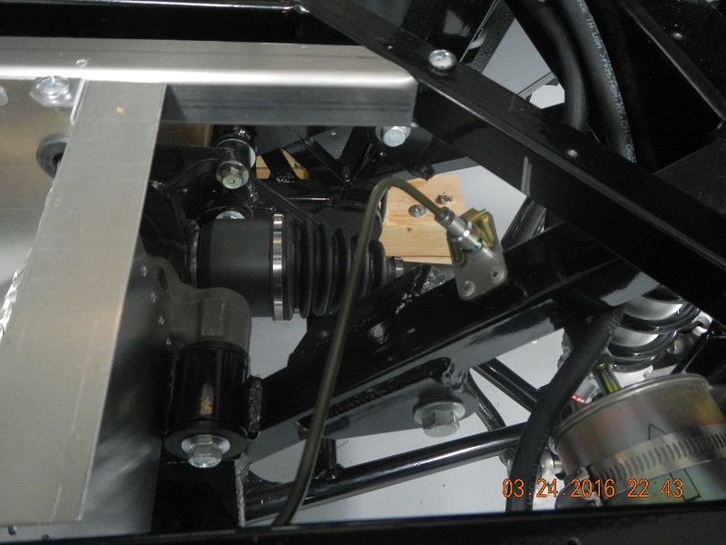
I spent most of today working on the dash layout, making lists and ordering parts. I got the E-Brake cables laid in, but realized that because I routed the cables over the 4" main rail, the cables are too long. After consultation with an expert (thanks EdwardB) I realized I had to order the Lokar e-brake kit. To the keyboard to shop.
I then moved on to the Forte Master cylinder. The kit looks top notch. The M/C is from Willwood so that's a good start. It came with two different size reservoirs, neither of which I am going to use. I then went off on a long search for the correct fittings to go from the 11/16"-20 fitting on top of the M/C to 3/8" hose to connect to the FFR reservoir that I already have mounted. First problem: finding any adapters that are 11/16"-20. It seems that Willwood in their wisdom decided to use a fitting size that almost no one else uses. I finally had to settle on an adapter that will go to the -3 AN Brake line fitting. I will drill it out to allow more flow, and then attach a 3/8"nipple to it. This should allow the 3/8" reservoir hose to flow into the M/C. Ordered these parts. Next I moved on to the outgoing end of the M/C. First problem: it comes straight out the back of M/C, in exactly the wrong direction. I have to find fittings to make a 180 degree turn before I hook it into the hard line that will be connected to the receiving end of the clutch fluid: The clutch itself. had to find multiple adapters to get the fitting going in the right direction. Time will tell if all these adapters, connectors, and fittings will effectively transfer the fluid to the right place.
One problem I did discover: The shaft on the clutch M/C appears to be too long. After installing it and adjusting it to be roughly in the right place, the shaft bottoms out on the top of the clutch pedal. I think I will have to cut about 1/2" off the M/C shaft. Not a problem, just wanted to be sure I wasn't missing anything.

Last edited by Jazzman; 03-30-2016 at 02:48 AM.
-
03-27-2016, 06:08 AM
#166
Senior Member
Just to confirm, the only part I used from Lokar is their S-8078 Parking Brake Cable Clevis. It could be used as is, or modified a bit like I showed in my build thread. The Lokar part allows the shortened cables to be clamped in place plus allows adjustment without taking everything apart like the stock setup.
I too had to cut about 1/2 inch off the Wilwood clutch MC provided by Mike Forte. Doesn't look like you've gotten there yet, but the pushrod he provides for the slave cylinder is also oversized. It needs to be cut to size when you install that end of the system. I have an idea. Mike should get with Mark at Breeze and maybe collaborate on some Breeze-like instructions. Wouldn't that be something? ")
Build 1: Mk3 Roadster #5125. Sold 11/08/2014.
Build 2: Mk4 Roadster #7750. Sold 04/10/2017.
Build Thread
Build 3: Mk4 Roadster 20th Anniversary #8674. Sold 09/07/2020.
Build Thread and
Video.
Build 4: Gen 3 Type 65 Coupe #59. Gen 3 Coyote. Legal 03/04/2020.
Build Thread and
Video
Build 5: 35 Hot Rod Truck #138. LS3 and 4L65E auto. Rcvd 01/05/2021. Legal 04/20/2023.
Build Thread. Sold 11/9/2023.
-
03-27-2016, 12:56 PM
#167
Jazzman, I have the same battery box and rear end. Seems that they will rub. Did you raise your box some or did you remove some of the front of the box. Still have not mounted mine yet but have decided to do one of the two instead of relocating the battery somewhere else. Nice build. Way ahead of me. jim
-
03-30-2016, 02:20 AM
#168
Originally Posted by
RR20AC
Did you raise your box some or did you remove some of the front of the box.
Jim, I did not modify or raise my battery box at all. It fits perfectly between the upper differential mounting points. Since the differential is mounted in four places to very stout beams, It better not be moving at all. (If it is moving, I think you have even bigger problems!) I would suggest you wait to permanently mount the battery box until you have all your brake lines, fuel lines, and all wiring routed, and all the attachment holes located and drilled. It gets very busy under there with all these things going on. It would have been much easier to attach several pieces if that box had not been permanently attached. I wish I had thought of that before I attached my own box! Whatever you do, don't attach either of the trunk floors or the back wall of the cockpit until you are sure everything is run and permanently attached. You will need to run the differential vent tube before you install the battery box. If you plan to replace the differential gear oil, you should do this before the box goes in. It is not impossible to change the gear oil after the battery box is in, but it will be very difficult! I couldn't figure out a way to improve on that design, so I changed the fluids and then installed the box. If It needs service in the future, I will have to live with the consequences.
-
03-30-2016, 02:44 AM
#169
I'm doing some pre-wiring planning. I have decided to use a master cutoff switch and install it in the trunk just forward of the battery box. (pictures will have to follow later when the switch can be installed.) Because of all the computer circuits that will require an "always on" power circuit, I am going to be running two master hot lines from the master cutoff switch to under the dash: the main "switched" battery cable, and a smaller "always on" line. Under the dash they will each go to their own buss bar. Questions:
1. The main battery cable is 4 gauge. I don't think the "always on" circuit will need to be that big. How large a cable should I install to feed all the "always on" circuits?
2. How large a buss bar should I install to handle all the various circuits? Same size for both switched and un-switched circuits? Source?
-
03-30-2016, 06:50 AM
#170
Senior Member
Originally Posted by
Jazzman
I'm doing some pre-wiring planning. I have decided to use a master cutoff switch and install it in the trunk just forward of the battery box. (pictures will have to follow later when the switch can be installed.) Because of all the computer circuits that will require an "always on" power circuit, I am going to be running two master hot lines from the master cutoff switch to under the dash: the main "switched" battery cable, and a smaller "always on" line. Under the dash they will each go to their own buss bar. Questions:
1. The main battery cable is 4 gauge. I don't think the "always on" circuit will need to be that big. How large a cable should I install to feed all the "always on" circuits?
2. How large a buss bar should I install to handle all the various circuits? Same size for both switched and un-switched circuits? Source?
For DD's, the ignition off draw for the PCM, clock, radio memory, etc. is in the 30 milliamperes range. Very low. I would expect yours would be similar. It's not going to take much of a wire for that. A common size like 16-18 AWG would be more than adequate. To be honest, I'm not sure a bus bar is required for that one. It should only have a couple things attached to it at most. I would just tie them together. If you're planning more than that for the always on circuit, it will drain your battery pretty quickly. For the power side, I've used this bus bar and will have one again in my new build: https://www.bluesea.com/products/230...uds_with_Cover. Available at Delcity, Amazon, West Marine, etc. Anything from this company is decent quality since their stuff is designed for marine use. Hopefully you're not taking the 4 AWG battery cable directly to this though. That should go to the firewall.
Build 1: Mk3 Roadster #5125. Sold 11/08/2014.
Build 2: Mk4 Roadster #7750. Sold 04/10/2017.
Build Thread
Build 3: Mk4 Roadster 20th Anniversary #8674. Sold 09/07/2020.
Build Thread and
Video.
Build 4: Gen 3 Type 65 Coupe #59. Gen 3 Coyote. Legal 03/04/2020.
Build Thread and
Video
Build 5: 35 Hot Rod Truck #138. LS3 and 4L65E auto. Rcvd 01/05/2021. Legal 04/20/2023.
Build Thread. Sold 11/9/2023.
-
03-30-2016, 10:46 AM
#171
Not a waxer
Everyone has different needs and desires but FWIW I like to have the battery switch in the cockpit where it's easy to reach, specifically on the horseshoe at the front of the tunnel. Personally I wouldn't want to have to go to the trunk to use it.
Cheers,
Jeff
-
03-30-2016, 07:31 PM
#172
Thank you, Jeff, for your comment. You are certainly one for whom I have great respect. I thought about that location, as I have seen it there several times. I decided to put it the trunk for three reasons. My primary purpose for the switch is security. By locating it in the trunk it is out of view and locked up tight when I am away from the car. Secondly, I was concerned about water and grime getting into the connections. Finally I am working on building a small accessible storage space in that space. Thank you so much for keeping an eye on my build. Your input is always greatly appreciated!!
-
03-31-2016, 02:35 AM
#173
Originally Posted by
edwardb
DDHopefully you're not taking the 4 AWG battery cable directly to this though. That should go to the firewall.
Ok I'll ask the obviously uneducated question: why? I had sort of planned to go in linear fashion, branching power off this buss bar as needed. What am I missing?
-
03-31-2016, 09:58 AM
#174
Senior Member
Originally Posted by
Jazzman
Ok I'll ask the obviously uneducated question: why? I had sort of planned to go in linear fashion, branching power off this buss bar as needed. What am I missing?
The largest current draw (by far) for your battery cable is the starter. So it's very important to take the shortest most direct route to the starter first. For a stock installation this means the battery cable goes directly to a firewall mounted solenoid and then another shorter cable of the same gauge goes to the starter. Taking a detour in/out of the area behind the dash likely would add length to the cables, be challenging to fit into an already crowded area, plus it's generally not considered good practice to have those high current cables behind the dash. Best if they're left outside the dash/cockpit area along the floor or frame and then into the engine compartment. The RF harness is designed with three attachments to join the battery and starter cables at the solenoid: Battery, ignition, and alternator. Those wires will bring the necessary +12V to the fuse panel in the DS footbox, charge the battery, etc.
So that's the "stock" answer. Since the permanent magnet gear reduction (PMGR) starters that are pretty much the norm now have an integrated solenoid, technically a firewall solenoid is no longer needed. But it's still an easy gathering point for the wires, so some still use them for that reason. I haven't used one in any of my builds. I've used the master disconnect for that purpose. Since you're planning to put your master disconnect in the trunk, which I understand since you are doing a rear battery and a front console, and if don't want to mess with a firewall solenoid, you could use something like this: http://www.summitracing.com/parts/rfw-jb47/overview/. Or this: http://www.summitracing.com/parts/prf-80114.
Hopefully others will chime in maybe have some different or better suggestions.
Build 1: Mk3 Roadster #5125. Sold 11/08/2014.
Build 2: Mk4 Roadster #7750. Sold 04/10/2017.
Build Thread
Build 3: Mk4 Roadster 20th Anniversary #8674. Sold 09/07/2020.
Build Thread and
Video.
Build 4: Gen 3 Type 65 Coupe #59. Gen 3 Coyote. Legal 03/04/2020.
Build Thread and
Video
Build 5: 35 Hot Rod Truck #138. LS3 and 4L65E auto. Rcvd 01/05/2021. Legal 04/20/2023.
Build Thread. Sold 11/9/2023.
-
04-06-2016, 01:30 AM
#175
More wiring, odds & ends.
This month will be a wild one, but I am finding a little time to work on the Roadster. I spent a good amount of time working on the design of the dash. I know I have probably spent an inordinate amount of time in that area, but I want it to be a signature part of the overall design. No photos yet. I still am not quite sure how I will finalize the design. I made a template of the dash and have been moving around paper cutouts that represent gauges, switches, etc. It is very hard to do something that one of the other geniuses have not already done. More on that after some question marks fall into place.
I am still working on laying in the wiring that I have. I decided to put my main cutoff in the trunk to enhance its security nature. Putting it right at the center of the upper level of the trunk works great to get it out of the way, and give you a solid mounting point. (its a steel panel under there!)

I decided to eliminate the part of the wiring harness that was only for the 33 Hot Rod. I clipped the wires short, sealed the ends with shrink tape, then wrapped it all up inside electrical tape. I really don't think I will ever need any of these lines, but at least if I need them, I can still tap into them.


I went to attach the wiring to the fuel pump and fuel level sender. The clip fit the fuel pump perfectly. Went right on with a light pressure and a solid click. One down one to go. The fuel level sending wire would not go on neatly. I checked the wire clips inside the quick disconnect plug. One has slid to the right and would not engage. I encouraged it back into place and the clip slipped right into place followed by a . . . very unsettling crack and the sound of the retention clip breaking off! Arrrrgh!! Going to have to call FFR to get counsel on what to do about this problem.

I came across the filler piece for the hole in the PS F-Panel. I decided to install right away so I wouldn't lose it again. Nothing special here, just progress.

Finally, I moved the clutch and brake pedal ends from the center mounting holes to the right mounting holes. (moves the plates to the left) I think this will provide just a bit more foot room for the gas pedal, and still leaves plenty of space for my left foot to the left of the clutch. The recent modification of the outside panel of the DS footbox seems to have been a good choice. Thanks FFR.

Last edited by Jazzman; 04-06-2016 at 01:41 AM.
-
04-06-2016, 02:06 AM
#176
I finally got around to using the can of POR 15 I bought a couple of months ago. I really love this stuff!! I will not ever spend any money powder coating anything black. I used the POR 15 to protect the new structure I built around the dropped trunk box. Just like the instructions said, it took two coats. I was surprised how long it took to dry in the relatively higher temperatures and lower humidity that we have here in Arizona. It still took about six hours before I could re-coat the pieces. After 2 coats and 12 hours to cure, it is like black porcelain. Beautiful.
Some comments:
1. the smell is not as bad as I had expected. Perhaps that is because I have spent a bit too much time around solvents, finishes, removers, stains, and assorted other finishing chemicals. Yes, you will want to use it in a ventilated area, but it really isn't too bad.
2. they say not to get it on your skin because you really can't get it off. They aren't kidding!! (again, ask me how I know.)
3. Don't get it on your clothes unless you simply don't care how the clothes look. Reference point #2.
After getting the trunk area painted and cured, I finally put in the dropped trunk box for the last time. I know it is the last time, because I then welded the last frame rail around it. That box is not coming out of there!!

Before I put the box in, I fitted the bottom and sides of the exterior of the box with sound/heat deadening sheets just like other panels. After the box was installed, I had to attach the last two panels of sound/heat deadening material. It took some careful measuring and weaving into the space, but it installed just as it should and looks like it will protect that panel from excessive heat.
-
04-06-2016, 06:19 AM
#177
Senior Member

Great job on the build! Nice and clean. Really like your PC choice and regret not doing the same.
Kyle
Complete Kit pickup 09/05/2015, 351w, QF680, 3.55, 3-Link, 15" Halibrands with MT's, Painted Viking blue with Wimbledon white stripes on 03/15/2017. Sold in 08/2018 and totally regret it.
-
04-06-2016, 02:07 PM
#178
Thanks for the compliment Kyle. Other builders set a very high standard, but also help you get there. If mine comes out well, it will be because I am standing on the shoulders of giants!
-
04-10-2016, 06:49 PM
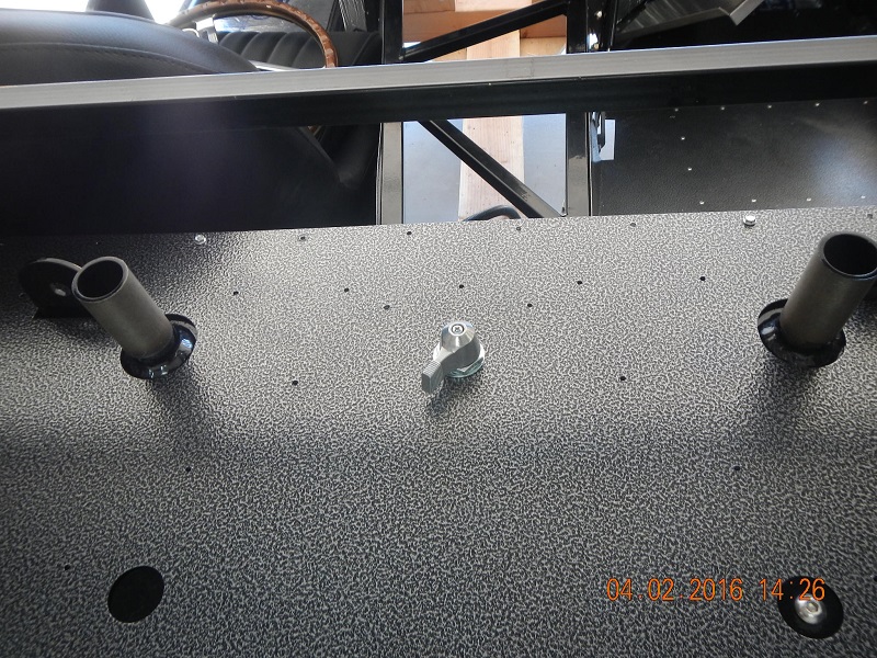
#179
Without an engine and Tranny right now, I am finishing up small details in preparation for putting the body back on for the first time. I want to fit the dash, measure a few things, etc. I have been working on installing (but not permanently) the floor panels in the trunk and at the rear of the cockpit. I don't want to get those installed permanently until I am sure I have all the wiring, etc, done back there. Even with that access, it is still busy under there! They still have to be insulated anyway. Just a dry run for now.
Someone mentioned a steel cage to go around the drive shaft. What is it, where do I find it, how critical is it for a non-race oriented vehicle, and is it already too late to install it with the floor panels permanently installed?
According to Edwardb, I really do not need a solenoid for a current type starter, but I will need a convenient gathering point for the power distribution in the engine compartment. What do you think about this Junction Block?

I am thinking this might solve two problems at once. This would get power directly from the battery, then route it to the starter, but would also get power through the firewall to keep from having any more unsightly wires in the engine bay to get power back inside for all the other needs. Any reason to have more than one of these? Basically, I am putting a DelCity order together, and want to order as much as possible at one time to keep shipping costs down. I am already ordering 3/8" wire loom and 3/8" cable clamps. Suggestions on what I will likely need? Come on, help me spend my money!!
Last edited by Jazzman; 04-10-2016 at 06:51 PM.
-
04-10-2016, 08:48 PM
#180
Carl

Jazzman,
I too have suffered from the addiction to DelCity and have a box full of stuff to show for it ...
I don't know if you are considering fusing any of the unswitched loads in the engine compartment but if so you might consider one of their fuse blocks like the one linked below:
http://www.delcity.net/store/search/...jsp?item=73820
For any connections in the engine compartment I used their terminals (spade, ring, butt for example) I used the terminals with heat shrink fitted. The ones with a glue are nice but probably going overboard.
http://www.delcity.net/store/Terminals/
I also don't really like standard electrical tape ... The stuff deteriorates in the heat into a mess ... I use the self sealing tape
http://www.delcity.net/catalogdetails?item=235
Carl
Mk 4 Roadster
October 25, 2012 - Kit Arrives
April 8, 2013 - Build Starts
August 23, 2015 - Rolling Chassis/Engine & Transmission Installed
March 26, 2016 - Go Cart
-
Post Thanks / Like - 1 Thanks, 0 Likes
-
04-11-2016, 07:16 AM
#181
Senior Member
Originally Posted by
Jazzman
Someone mentioned a steel cage to go around the drive shaft. What is it, where do I find it, how critical is it for a non-race oriented vehicle, and is it already too late to install it with the floor panels permanently installed?
Called a drive shaft safety loop. Can be installed pretty much any time, including on a finished car. No worries about being too late should you decide you want one. They're a safety item meant to keep the driveshaft contained should one of the U-joints fail. They are typically required by safety rules for track events, etc. It's a little interesting when you see how close the spinning driveshaft is to your backside while sitting in the car. But for street use, strictly your call. Many (maybe most?) drive without one. Others choose to install one. There are at least three options. Mike Forte sells a custom one just for these cars that is sort of a bolt on. It bolts on after you install four pretty large inserts into the 4 inch frame tubes. There are various universal ones that are pretty inexpensive. Probably one of the nicer and easiest to install is one from Metco, but they're only occasionally available. This thread talks about it: http://www.ffcars.com/forums/17-fact...haft-loop.html
Build 1: Mk3 Roadster #5125. Sold 11/08/2014.
Build 2: Mk4 Roadster #7750. Sold 04/10/2017.
Build Thread
Build 3: Mk4 Roadster 20th Anniversary #8674. Sold 09/07/2020.
Build Thread and
Video.
Build 4: Gen 3 Type 65 Coupe #59. Gen 3 Coyote. Legal 03/04/2020.
Build Thread and
Video
Build 5: 35 Hot Rod Truck #138. LS3 and 4L65E auto. Rcvd 01/05/2021. Legal 04/20/2023.
Build Thread. Sold 11/9/2023.
-
04-20-2016, 07:18 AM
#182
Senior Member

Getting a lot of good info from this thread. Thanks! Sent you a PM
-
04-21-2016, 01:29 AM
#183
Thanks for the compliment WarEagleScott. I am glad it is helping you. Two PM's sent to you.
-
04-23-2016, 11:01 PM
#184
The TILT is IN!
I have been rather silent and unproductive for the past few weeks because there has been a lot going on. My son married the girl of his dreams last Saturday, and yesterday they both graduated from college. I am so thrilled and proud of both of them. It has been great having extended family around a lot over the past few weeks. I have shown off the Roadster many times, received a lot of compliments, but have not really had much time to do anything. What time I did have was devoted to evaluating the feasibility of a really big decision: would I take the risk of attempting a tilt front on my very first car?
If you have gotten this far in my thread, you may remember I have wanted to do a Tilt Front from the beginning, but had decided against it. With the help of all my friends on this forum, I have had an amazingly smooth build process thus far. IN only four months (I am ignoring the past month that I really have done next to nothing) I have gotten farther than I expected to get in the first full year.
Over the past few weeks, I have exchanged innumerable emails with 2bKing. If you haven't already read his build thread, I highly recommend it. He drew inspiration from Dallas, and now I can learn from both of them. I have exchanged emails with MikeinAtlanta who very kindly agreed to assist me, but we have not yet had a chance to actually talk. (Sorry, Mike!!) Mike is an expert in fiberglass work, materials and methods. After consulting these experts, re-reading 2bKing's build thread for a third time, I have made a decision. My original purpose for this project was to learn as much as I could. With their help, I believe I can do a tilt front. I have no time limit on the project, and I am enjoying it immensely. I am going to do the Tilt Front!
2bKing has been exceptionally helpful in this process. He has agreed to counsel me through the process, and I have promised to thoroughly document my journey for him. Let it be fully known that this is NOT my design, but is developed by 2bKing. His skills are well above my own, and I so appreciate his assistance, wisdom, and insight.
I have already begun modifying slightly his design to simplify it a bit. I began the process today by beginning the layout process. After doing it, I came up with a shape that I really like, but it is a little different than what 2bKing did. His separation line over the top of the body parallels the curve of the windshield. Mine is a bit more complex, but retains the support "flange" where the hood will intersect with the body. In this installation several key decisions are different from his original design:
1. My modified design will retain the inner layer of the original FFR hood, and retain the structural ribbing around the outside edge of the underside of the FFR hood, hereinafter referred to as the “old hood”.
2. My modification will separate the “Hood” section (the entire front half of the car including the old FFR hood) from the Body section at the same point that the old hood currently meets the body just in front of the windshield. By using this already established demarcation point, you will retain the ledge (flange) that the hood will rest upon. This should provide stability and possibly reduce the fiberglass work.
3. My modification will include a working hood scoop. Much has been debated about the relative merits of a working hood scoop at higher speeds. (It will not be re-debated here!!) I like the working scoop. I put it in. You can choose not to include it just as easily.
4. I will include hood louvers purchased from Vraptor Speedworks. Merely a personal choice. I like them!
I began the cut line layout process.
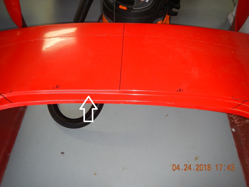
1. Using one of the cardboard shipping boxes laid out flat over the top of the body, trace a pattern of the body along the front of the cockpit area. Continue the pattern over the sides of the body going a short way down the side of the body. Cut out this template. Find the exact center point of the template and draw a line. Make additional marks 13” to each side of this center line.

2. Using another box, lay one of the doors on the box, outside down. Line up the top of the door with the edge of the box. Trace the door onto the box, creating a template. Cut out this template, then cut off the last 12” of the template. It will just be in your way!


3. Measure across the hood area of the body at several points to find the centerline of the car. Measure multiple times, as there are no perfect locations to measure from on this very complex shaped body. Once you have found the center line of the car, draw a line with a sharpie to mark the center line of the car. I chose to go all the way from the front of the car to the rollover at the dash.
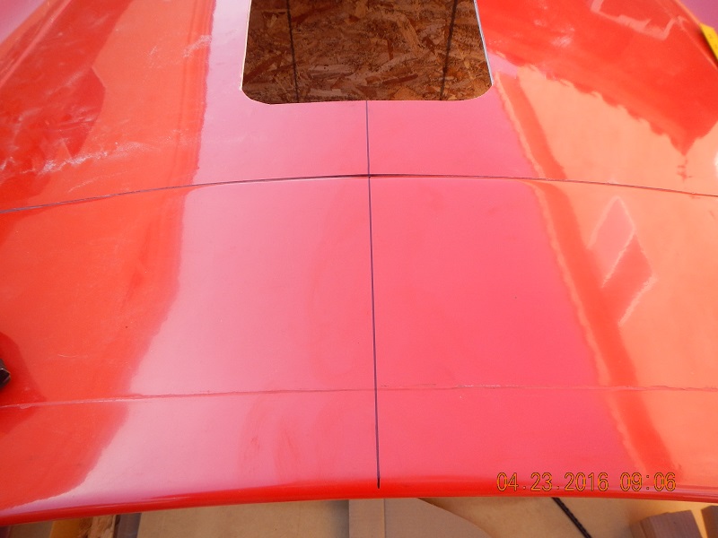
4. Make a mark 13” from the centerline to each side of the body along the edge of the hood/body seam. Do one of these both to the right and to the left on the body side of the separation

5. Using a long straight edge ruler, draw a line following the rear edge line of where the old hood meets the body nearest the cockpit. (It should go across the car, same direction as the windshield. This new line should extend all the way to the manufacturing seam lines in the fiberglass body. Do this on both sides of the old hood.


Last edited by Jazzman; 04-23-2016 at 11:40 PM.
-
04-23-2016, 11:19 PM
#185
-
04-23-2016, 11:34 PM
#186
-
04-24-2016, 04:20 AM
#187
Carl
Jazzman,
Very impressive ... and great documentation of the process. After seeing Dallas' tilt front, the access this modification gives makes servicing the roadster very easy compared to the standard version.
Carl
Mk 4 Roadster
October 25, 2012 - Kit Arrives
April 8, 2013 - Build Starts
August 23, 2015 - Rolling Chassis/Engine & Transmission Installed
March 26, 2016 - Go Cart
-
04-24-2016, 07:13 AM
#188
Senior Member
Wow. Big decision on your build and looks like you're off to a great start. Should be very cool. I've communicated with 2bking several times so far during my build, especially when I was using his modded footbox. Great guy and very willing to help. What makes this community such a good place. Good luck.
And congratulations on the wedding and new daughter-in-law. Those are beautiful and very special times.
Build 1: Mk3 Roadster #5125. Sold 11/08/2014.
Build 2: Mk4 Roadster #7750. Sold 04/10/2017.
Build Thread
Build 3: Mk4 Roadster 20th Anniversary #8674. Sold 09/07/2020.
Build Thread and
Video.
Build 4: Gen 3 Type 65 Coupe #59. Gen 3 Coyote. Legal 03/04/2020.
Build Thread and
Video
Build 5: 35 Hot Rod Truck #138. LS3 and 4L65E auto. Rcvd 01/05/2021. Legal 04/20/2023.
Build Thread. Sold 11/9/2023.
-
04-24-2016, 11:36 AM
#189
cobra Handler

Surprise!!!!!! This is the last thing I thought I would see on your build thread. But I am pleasantly surprised. I do like your design with the retaining of the ribs on the front end portion. It will add strength and save a lot of work as well as the keeping the inner liner on the hood. Are you planning to use the truss brackets or are you going more for the coupe design? I would like to do this one day but I will let you beta builders perfect the process for me first! I'm taking a copious amount of notes though.
Good luck,
WEK.
FFR MkIII 302 (ATK), EFI 75mm TB with custom box plenum chamber, 24# injectors, 4 tube BBK ceramic, cold air sys, alum flywheel, crane roller rockers, T5, Wilwood pedals, custom five link with Watt's link, 4 rotors, coil overs, power steering with Heidt valve, alum FFR rad, driver's crash bar mod, mini dead pedal mod, quick release steering wheel hub #6046
-
04-24-2016, 01:06 PM
#190
 Administrator

Kevin,
Congratulations on tackling this mod! I'm sure you will love the result!
I do have a concern though. That is using the top of the hood as the demarcation point. I'm concerned that the new hood will not be sturdy enough without using some of the body above the hood to help give the new hood proper rigidity. Have you discussed this with 2bKing?
I'm excited for you. This is definitely going to take your build to a whole new level!

FFR 5369 Pin Drive, IRS, Trigos, Torsen, Wilwoods, FMS BOSS 302 "B" cam , Mass-flo. CA SB100 (SPCN) Registered
Delivered 4/23/06. "Finished" 4/2012 (still not done!)
-
04-24-2016, 02:17 PM
#191
Jazz-
So very cool! I admire and respect those of you that take on this project. I really like the tilt front, but there is no way I have the courage to do it myself.
King has done a great job on his, and I know you will receive expert advice! Likewise Mike will be a great resource for your fiberglass work! You have truly expert resources to help you in your journey!
I second Paul's comments regarding the expanding family and the recent commencements as well. Congratulations.
I will be following your progress like many others I am sure. Best of luck as you move forward, and steady hands for that first and subsequent cuts!
Regards,
Steve
-
04-24-2016, 03:09 PM
#192
Member

Mr Jazzman
After looking at Dallas and studying 2BKING I will be following you since I plan to drive for about 1 year in gelcoat,
then I plan to put the body under the knife. I will be looking to see what your plan is for the hinge. It does take
courage but as someone told me it is only fiberglass.
thank you for the pictures of your progress.
From #8851 still doing inventory
Cecil
-
04-24-2016, 07:55 PM
#193
Thank you all for your comments and support. This is certainly not an aspect of the build that I would even consider without the assistance of those more experienced than myself.
Originally Posted by
David Hodgkins
I do have a concern though. That is using the top of the hood as the demarcation point. I'm concerned that the new hood will not be sturdy enough without using some of the body above the hood to help give the new hood proper rigidity. Have you discussed this with 2bKing?
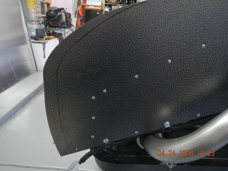
I have, indeed, discussed this with King, but I welcome other perspectives. Here's my/our thinking. (Please chime in 2bKing if you have other thoughts. Dallas, too, for that matter!!) Here is a photo of the inside of the "old Hood".

This two layer section already has a structural rib running along the edge, a form that I would have to create with new fiberglass and other materials if I made the cut any closer to the windshield. King did cut closer to the windshield, and build additional structural ribs to support the hood and to support the body just behind the cut line. As I cut through the "old hood" for the air scoop and hood louvers, I will likely find places where the two layers of fiberglass are not strongly bonded together. I am hoping that I can find enough of these points that I can separate the layers slightly, fill the rib area with some sort of expanding foam which will get very solid and rigid after it drys. (I'm thinking about a similar product to that expanding foam stuff you can get at Home Depot to seal windows and doors and fill gaps in your home insulation. Probably not exactly that stuff, but something similar.) After all the voids are filled I plan to using a bonding material to glue the two layers back together, forming a very strong joint. Then I am going to add structural ribs similar to what King did on the sides and across the top just in front of the air scoop. Conceptually I want to use the strength of the ribs that are already there, improve them, then add additional ribs for added strength and stiffness.
The hood section will sit on this ledge already provided by FFR:
I will add a full structural rib on the underside of the body using this ledge as the front section. The idea is that both sides, body and hood, will have full structural ribs on either side of the cut line where they are separated. All of these ribs, all the glass work, will be done before the body is cut. The idea is to retain the original shape while the additional supports are being added.
OK. Have I convinced you? Got any better ideas? I'm sure open to them!!
-
04-24-2016, 08:34 PM
#194
When I put the body on for the first time yesterday, I was surprised that it just barely fit. The frame and rear sheet metal seemed to be too long. I found that the sheet metal at the rear, the two sides and the lower trunk floor panel were right up tight against the fiberglass. However, there wasn't even any bulb seal in there, and the body was far enough back on the frame that the door hinges would not open. They struck the inside of the body. I was contemplating this problem, measuring, and trying to figure how much to cut off, when I received a very timely email from 2bKing. He told me that he, too, had to cut off the rear sheet metal to make the body fit and the bulb seal have room to do it's job. This made me feel so much better. So today I measured again, and decided to cut off 1.125" from the rear side sheet metal, and 1.375" from the rear of the lower trunk floor panel. (The lower panel is already 0.25" too long.) Theoretically, this should allow the body to move forward by the 0.675" that it needs to be in the right place, and allow 0.5" for the bulb seal. I sure hope I have figured this right!! Messing this up will involve buying new side panels and re-powder coating them. Definitely not the plan!

-
05-10-2016, 02:16 AM
#195
Huntington Beach Cruise In, Great help from MikeinAtlanta
We had a great time at the FFR Huntington Beach Cruise In. It was great getting to meet quite a number of you during the two days of events. It was a great show. There were dozens of truly amazing builds. I was inspired by attention to detail in many of the cars, both in the Roadster line as well as GTM's, Coupes, Hot Rods, and 818's.
The show really reinforced how helpful the FFR community is. I was reminded of this yet again last Friday. I had the pleasure of speaking with MikeinAtlanta for over an hour. For those of you that do not know, he is a genuine expert in composites, and is a true artist as a fabricator. He was kind enough to share his photos of his FFR Roadster "Little Boy". The custom fabricated fiberglass work and aero effects are truly show stopping! Mike gave me a one hour master class in the chemistry and methods of fiberglass, vinylester resins, epoxies (don't use these), HSRF fillers, and many other topics related to the customization of the FFR body. I took copious notes, but still will likely have to call him back because he is so very knowledgeable. Thank you, Mike, for giving of your time to help me. You are truly one of the great ones!
-
05-10-2016, 02:37 AM
#196
Hood support Truss Fabrication
I was able to spend most of this past weekend working in the shop. It was great to get back to the Cobra project. I spent part of Saturday disassembling and rebuilding the body buck. I wanted to move it inside the garage so that I can work on the body and yet roll it outside when necessary. I narrowed the body buck a bit, and adjusted the height to make it a more appropriate working height as well as providing full support along the bottom of the body. My father was over at the house working on his own project. It took both his and my wife's assistance to get the body buck rebuilt. (It is quite unfortunate that now that my boys are both able to help with this type of project, one is out state and the other is married and across town. This empty nest thing has it's downsides!!) Anyway, not much to show, but the buck is rebuilt and the body ready for the next steps in fabrication.
I am still borrowing my friend's welding rig, but I figured I had better get it back to him soon. I spent the rest of the weekend fabricating the support trusses according to 2BKing's plans. I first cut the 3/4" square tubing to length, then laid out the notches that had to be cut in the upper and lower main support tubes. To get the angles set up correctly, 2BKing has instructed me to cut notches not quite all the way through the square tube.

After cutting all the notches with the sabre saw and cleaning up the notches with the die grinder, I bent the tube and confirmed that the angle was exactly as indicated on 2BKing's plans.

I then built a template board so that both trusses would have exactly the same top shape. I took a 2'x4' piece of junk particle board and screwed blocks on each side of the square channel to hold it in place. A bit of tack welding kept the bent tubing in shape.

I then fabricated the vertical (for lack of a better word) interior pieces. This took a bit of time to custom grind each piece to fit perfectly. I then tacked them into place.

The horizontal interior pieces were last, and required the most custom grinding to fit into the tight corners.
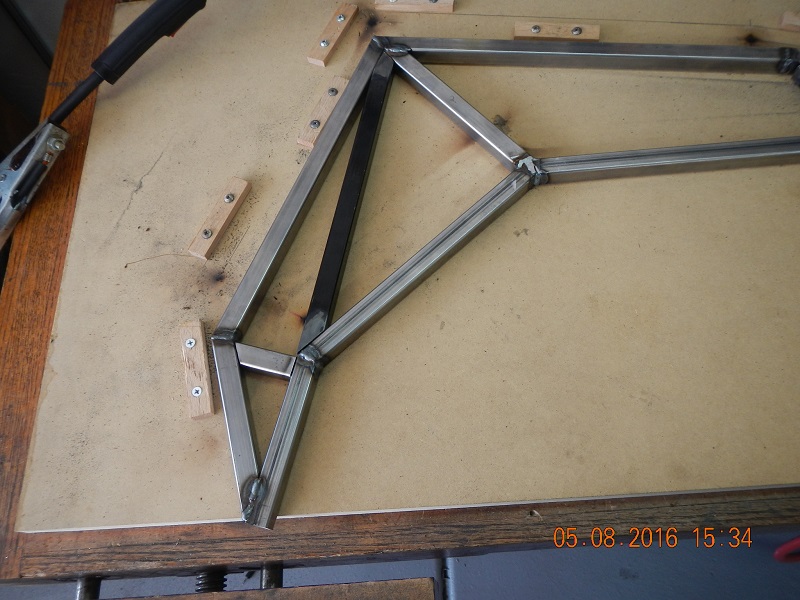
Finally I finished welding all the joints. While the welding is a long way from perfect, it seems to be strong enough. I am still working on grinding down some of the "less nuanced" welds, and repairing or replacing them. Practice makes improvement. I will work on grinding and polishing the welded joints, and ultimately send the trusses off to be powder coated.
Last edited by Jazzman; 05-10-2016 at 02:42 AM.
-
05-10-2016, 06:18 AM
#197
Senior Member
Originally Posted by
Jazzman
When I put the body on for the first time yesterday, I was surprised that it just barely fit. The frame and rear sheet metal seemed to be too long. I found that the sheet metal at the rear, the two sides and the lower trunk floor panel were right up tight against the fiberglass. However, there wasn't even any bulb seal in there, and the body was far enough back on the frame that the door hinges would not open. They struck the inside of the body. I was contemplating this problem, measuring, and trying to figure how much to cut off, when I received a very timely email from 2bKing. He told me that he, too, had to cut off the rear sheet metal to make the body fit and the bulb seal have room to do it's job. This made me feel so much better. So today I measured again, and decided to cut off 1.125" from the rear side sheet metal, and 1.375" from the rear of the lower trunk floor panel. (The lower panel is already 0.25" too long.) Theoretically, this should allow the body to move forward by the 0.675" that it needs to be in the right place, and allow 0.5" for the bulb seal. I sure hope I have figured this right!! Messing this up will involve buying new side panels and re-powder coating them. Definitely not the plan!
Wow, that is a fair amount to trim. I am hoping to fit the body this weekend and likely will have some trimming myself but didn't think it would be that much. Are those the only two areas for you?
Love the tilt mod you're doing. Daring and way too much for me to consider but will follow your posts as it is an awesome mod.
Kyle
Complete Kit pickup 09/05/2015, 351w, QF680, 3.55, 3-Link, 15" Halibrands with MT's, Painted Viking blue with Wimbledon white stripes on 03/15/2017. Sold in 08/2018 and totally regret it.
-
05-10-2016, 09:51 AM
#198
Originally Posted by
KDubU
Wow, that is a fair amount to trim. I am hoping to fit the body this weekend and likely will have some trimming myself but didn't think it would be that much. Are those the only two areas for you? Love the tilt mod you're doing. Daring and way too much for me to consider but will follow your posts as it is an awesome mod.
I have not yet done the trimming, but yes, thus far, that is all I have seen that will be necessary. Because it is such a large amount to trim out, I will probably reinstall the body yet again just to be double sure before I actually do the cuts. I may also do it in two stages, about half an inch each. I am not sure yet.
Thank you for the compliment on the tilt mod. Like many of the more aggressive modifications, this one seems to split the FFR builder community rather strongly. The more traditional builders seem to hate it. I have received a number of rather negative comments about it. "I just don't like the look." "It will hurt the resale value." "It is more work and expense than it is worth." While all those comments may indeed be true, I have also gotten a number of positive comments like yours, and they are greatly appreciated. One of the great things about this hobby is that unless you are specifically building the car to sell immediately to turn a quick profit, you choose the modifications that you want to personalize your car to your own taste. I think this makes for a very vibrant and creative environment. I may not want to do every choice and mod I see, but I certainly can appreciate the creativity and skill that each one takes to accomplish. Since these are all replicas anyway, I think the creativity Is great. Some want an "exact replica", recreating the original as closely as possible. (Of course, you end up with a replica.) Others want an "inspired by" or "homage" replica that attempts to take the best of the original and try to improve upon it. (Of course, you still end up with a replica!) I say build for your own joy, and let the chips fall where they may! You chose 15" wheels, a traditional pushrod engine, and a blue and white color scheme. GREAT! I chose 18" wheels, a non-traditional coyote engine, and will not be doing the traditional blue and white. Also good. To each his own!
I hope your build it progressing smoothly and you are having as good a time as I am!!
-
05-10-2016, 10:04 AM
#199
Senior Member

I would really double check the trimming. All those panels were installed when I got my car with the body on, something seems like it might have shifted. It might be a good idea to get someone else to take a "2nd opinion" look.
-
05-10-2016, 10:56 AM
#200
Steve >> aka: GoDadGo

Jazzman,
You are a much braver soul than this guy.
Measure twice and cut once or maybe measure three times just for fun.
Good Luck & Can't Wait To See The Final Product!
Steve / aka GoDadGo


 Thanks:
  Likes:


 Reply With Quote
