
Visit our community sponsor

Thanks:
10

Likes:
25
-
10-09-2016, 04:04 PM
#401
Senior Member

Ok some of my lurking .02 cents on this matter....
I think some of the beauty of FFR is you can go as big and bold as you want, or as basic and budget as you want. Either way you get an extremely safe and well engineered chassis. Basic kit is $12,990... You can find donor mustangs really cheap. Reading about all kinds of builds on different forums, some people don't even powder coat any of the panels. A little engine degreaser on the engine and their favorite rattle can color and in goes the engine. The levels are endless....
Some people build them in record time.... Some take years.... If you take the long road, that can also help you absorb some of the bigger costs if you go that route.....
Don't give up on the dream Dan
There are endless options....
Kurt
-
10-09-2016, 11:55 PM
#402
I couldn't have said it better myself, Kurt. I fully agree! Don't give up the dream Dan!!
-
10-10-2016, 12:26 AM
#403
This last little bit on cost, for those of use who are looking at numbers, but yet to pull the trigger, has been very useful. It is about what I am beginning to budget for. Well maybe your numbers are a little higher than my eventual build.  Thanks!
-
10-10-2016, 05:09 PM
#404
Senior Member
Hay Stork, I'm so jealous you got to drive David's cars!!! I'm always looking at numbers... And have yet to pull the trigger. But we are collecting special tools and small things we'll need in the future, it's like making payments lol Baby steps.... My wife said to start collecting little special things. Reading builds and knowing where we're gonna go on some things... Eastwood tubing flarer etc. etc. She even had us order our license plate lol it's like a goal.... Hang on the wall and see everyday. I'm also a big guy, 6'4"-5"? 280 cough 5 cough ish lol You and David have really set my mind at ease about fitting.... Thanks to both of you for that 
Kurt
-
10-10-2016, 05:39 PM
#405

Originally Posted by
SSNK4US

I'm also a big guy, 6'4"-5"? 280 cough 5 cough ish lol You and David have really set my mind at ease about fitting.... Thanks to both of you for that
Kurt
Yeah, I am "280 cough 5 cough ish" and then some. Like everything else, we fit, tightly!!
FYI for those of you in the greater Arizona/SoCal area (or anyplace else, I suppose, if you are planning a trip to AZ!). I am getting close to having to make a decision about what to do with my frame dolly. It served me well for the past year, but now is out from under the car. I am either going to have to give it away or keep if for my next build. SHHHH!! Don't tell my wife I said that!! "Of course not, dear, there is NO NEXT Build", nudge, nudge, wink, wink, Bob's your Uncle! If you are soon going to be starting a build, I might be willing to make you a present of it, and perhaps the body buck as well, as soon as I am sure I am done with both of them. PM me if you might be interested.
-
10-11-2016, 07:02 AM
#406
You did t scare me off, rather the opposite. I am somewhat hopeful that in the next 2-3-5 years the salvage market for IRS components becomes more reasonable. Having a realistic budget and build schedule, as well as two girls old enough to remember/enjoy the experience is key to getting started.
Keep up the good work.
-
10-11-2016, 09:05 AM
#407
Thank you very much for the clutch installation discussion. Saved me a ton of research and frustration. Much appreciated.
-
10-13-2016, 02:38 AM
#408


Two trips to San Diego to visit my son and his fiancée, a few very busy work days, and it is easy to get a long way behind on these posts. I have had a bit of time here and there to get a few things done. Mostly it has been filled with preparing to continue on the wiring, ordering a whole bunch of small parts, and waiting for them to arrive. So here are the highlights of what little I have gotten done over the past couple of weeks.
The fuel pressure regulator is in. I got the various connectors to screw into the regulator, and finally had time to install it. Because I had seen several people who had installed it low, and because I am not putting in a heater, I decided to attach mine a bit higher to the firewall. I placed it so that the primary fuel inlet line will go straight down just along the PS footbox wall.

To stiffen and strengthen the area that it was being attached, I used extra long rivets, and installed a left over piece of sheet aluminum on the inside of the firewall. It seems very solid.

Braided Stainless -6AN fuel grade hoses and end fittings are on order from Breeze, but have not yet arrived.
I received the Coyote engine mount 3/8" spacers from FFR. I hope you got these with your kit. They were not yet in production when I got my kit, so getting them cost me $135, but I certainly couldn't have made them myself without a lot of unnecessary work. They seem well made, but lets face it, they are nothing put carefully cut pieces of 3/8" sheet steel, not much to screw up here! I removed the engine mounts from the engine. I was going to have to do this anyway in order to set the engine down, extend the arm of the shop crane, and raise the engine up again to install it in the car. To put the engine on a temporary stand to do this required the engine mounts to go, so this worked out fine. The process of removing the factory bolts, putting the spacers in place, and installing the supplied bolts was quite straight forward.

A little pounding with a hammer to remove these original bolts.
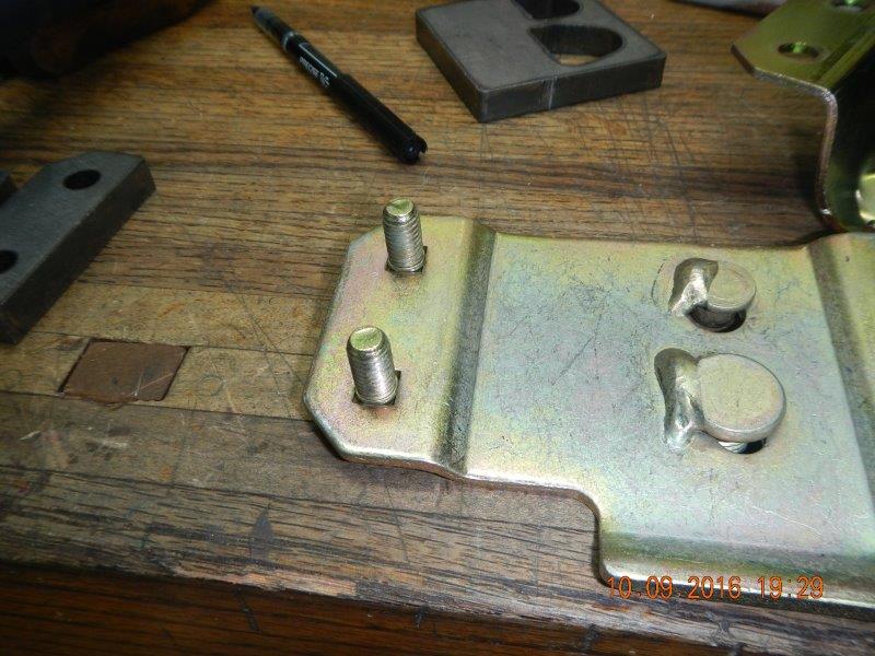

Lay the spacers in, line it all back up, cinch up the longer (provided) bolts. Easy peasy.

-
10-13-2016, 03:07 AM
#409
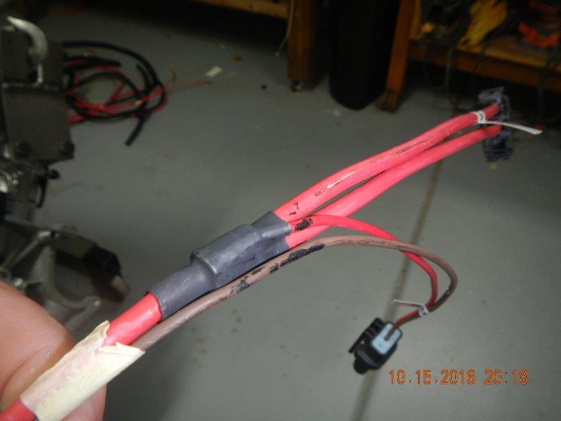
Wire loom simplification #1
In this photo you will notice there are two major cables running along the lower frame rail. The larger one is the main line from the PDB to the PCM (Plugs T & U for those of you who are trying to follow along in your Ford Performance Coyote Installation Manual), and the smaller one is the set of wires from Takeout BB that goes all the way around to the DS of the engine to connect to the alternator, the Mass Air Flow sensor (MAF) and the Intercooler connector for super charger (Not going to be needing that one I think!!).

The Ford instructions say to go around the engine with takeout BB, but I am trying to hide as many wires as I can. I want to take Takeout BB through the PS access hole through the firewall, across the area behind the dashboard, and then come out wherever necessary to hook these wires to their respective locations. Well, the anal retentive in me can't stand having two looms going in the same direction when only one is really necessary. SOOOOO . . . It is surgery time on both cables. BB has got to go. Well, more accurately, it has to go somewhere else! I opened up both the main cable and Takeout BB to see what was really going on. That took a lot of time because each one had to be very carefully opened up, and Ford used something like 60 miles of tape around those cables. After opening up everything I discovered what I suspected. Four of the wires in BB are coming from the PDB, and don't need to go all the way to the end only to turn right around and come back to the firewall again. Two reds, a green, and a black needed to be pulled out of the main cable set.

The other four wires, two blues, a purple, and a yellow, are coming from the PCM, and needed to be consolidated into the large main cable.

Four wires into the large wire loom, four wires out of the large wire loom, no problem. Just slow and methodical to be sure not to nick or crimp anything. After I had the four out and four back into the main loom all the way back to the corner of the firewall, I created a new cutout for these same 8 wires that were in BB, but now takeout BB is right by the hole in the PS of the firewall.


The wire bundles inside the looms are taped together for organization, but the external wire loom is only taped in a few key places to keep it from moving. I will ultimately wrap everything again, but for now I am leaving it accessible in case I need to add some wires, or perhaps correct a mistake (?). No, No mistakes on the wiring. I hope . . .
-
10-13-2016, 03:37 AM
#410
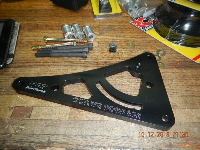
KRC Power Steering Pump Install
My KRC Power Steering pump kit arrived today. I wanted to get that on the engine and out of my way right away. I achieved partial success. Thank you's to EdwardB and BansheeKev for their write ups on installing this system. Without their help, it would have taken me a lot longer to figure out how to install this thing. The KRC product looks top notch. (I only wish it was polished instead of black, but that's just me!) The KRC installation instructions are almost non-existent! Yes there is a couple of pages of good info, but nothing about how to install the various bolts and spacers. It's not too difficult a puzzle, but it can waste some time if you don't know for sure. EdwardB did a great write-up in his thread, post #151. http://thefactoryfiveforum.com/showt...ry-Build/page4 I will add only my thoughts that he has not already addressed in his thread.
First, take off the serpentine belt and remove the pulley from the water pump. (Yes, that serpentine belt that you installed a few weeks ago when you got your alternator. At least you are getting good at it now!!)

remove the three bolts from the holes that EdwardB Shows so clearly in his post. You need to install the main support bracket for the pump, and to do this you have three long black bolts, threw washers, and three aluminum spacers that look the same length. However, upon taking a closer look you determine that one of these spacers is just slightly longer than the other two.
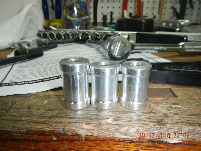
Set the one long spacer aside. This one is installed last and goes at the pointed left end of the pump bracket.
Be smarter than I was. Slide the silver nut inside the channel on the back of the pump bracket before you attach the bracket to the engine block. (Don't ask!!)

Install the top bolt through the bracket, through one of the two shorter spacers, then screw it loosely into the block. Yes, I used blue Loctite on them. Yes, I have been called obsessive before. Yes, I think you should too.

Install the other two mounting bolts in similar fashion. The longer aluminum spacer should be used at the far left end of the bracket.
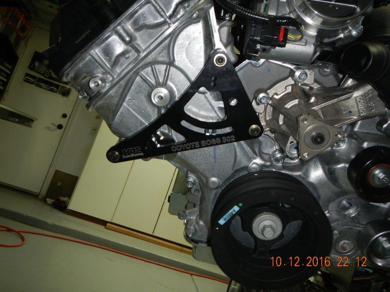
Find the replacement pulley for the water pump, the one with two places for belts to ride. There is a aluminum ferrule that needs to be installed in the center hold to match up with the shape of the end of the water pump. However, there is no instruction as to whether you put it in from the front or the back. After much study and testing, I can now confirm that you should install it from the back. No hammer required, just a strong pair of hands.

Put your primary serpentine belt back on. If you are like me, I had to refresh my memory what the pattern was for this belt.
Last edited by Jazzman; 10-13-2016 at 12:03 PM.
-
10-13-2016, 04:12 AM
#411
Now you can install the pump on the bracket. My kit came with two more spacers, longer than the others but much more narrow. The top bolt screws into the top hole in the bracket, and the lower bolt screws into the nut you installed in the chanel on the back of the bracket. By doing the mounting this way, the pump can pivot to take up tension in the small belt that will drive the pump.
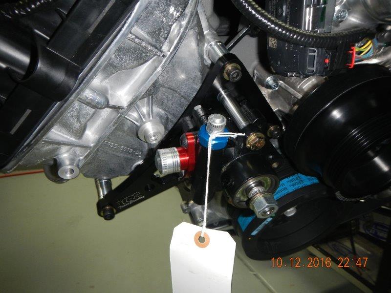
That blue item at the top of the pump is the flow valve. One of the benefits of this pump is you can choose how much assist you want, and change it just by changing this valve. Apperatlyl they are about $20 each. It is generally accepted that the #4 valve with a flow rate of 1.66 GPH is the most appropriate for these cars. I did not, however, glean that finer piece of information from the other posts on the subject until today, well after it would have been helpful. My pump came with the following valve:

2.85 GPH is going to be waaay too much boost. However, because I was not aware of the adjustability of this pump and it's interchangeable flow valves, I had already purchased an adjustable Heidts Valve. Now I have a decision to make. Do I keep the adjustability of the Heidts valve in the system, (the flexibility option) and accept the inherent additional connections that might leak, or do I try to return the Heidts valve and buy a #4 flow valve? (The cost saving option.) I am not sure how Summit is on returns.
Tonight I went back to the wiring just for a bit. I eliminated almost 30 inches of wire from the very long battery feed from the RF fuse panel and made just a short jump up to the primary Bus Bar. These three wires are "Battery FD", "Starter Sol", and a third, larger wire that I can't read! (FYI, I ordered three of these bus bars from Amazon, and each one was returned because they did not come with the promised plastic cover. I called Blue Sea Systems (the manufacturer of the bus bar) and asked them to send me two plastic covers. They were happy to send them out.

I still don't know what to do with the additional blue wire in this four wire set. it says "start Sol" on it. I'll find it sooner or later.
I received my package of fuel lines and fittings from Mark Breeze a couple of days ago. Installing the fittings takes just a bit of learning, but it's certainly not hard. Looks like a good system. I just realized I dont' have photos of those lines, so I will add them on a future post. One minor problem. Mark provided the following adapter to go from the stock FFR fuel lines to the -6AN hoses and fittings.

the -6AN side will work perfectly. It is the other end that concerns me. It is a compression fitting rather than a flared fitting. Mark's suggestion was that I use a tubing cutter to cut off the very end of the stock line, then attach these compression couplers. I can do that, but it will require drilling out the rivets that hold the fuel lines all the way back to the rear end to get enough room to spin a tubing cutter around the fuel lines. Does anyone know of an adapter that will go from the 1/4" or 5/16" flared end of the fuel lines and adapt to the male side of a -6AN fitting?
EDIT -- Here is a photo of the braided stainless lines installed, at least at the pressure regulator end.

Last edited by Jazzman; 10-14-2016 at 02:22 AM.
-
10-13-2016, 04:29 AM
#412
Senior Member

Nice work Kevin.
For your planing on the routing and length of the maf sensor plug wires be aware that the sensor needs to be positioned on the front side of the 4" tube. You will need to take the cable over or under the tube to reach around to the plug it point. I ran mine without realizing this and barely had enough length because I thought I would plug it into the tube on the side closest to the driver. Just a heads up.
I am in a hotel on layover all day today. I will look back through all the messages and see if I can find the definitive answer on that blue wire.
MK4 #8900 - complete kit - Coyote, TKO600, IRS - Delivered 6/28/16 First Start 10/6/16 Go cart - 10/16/16 Build completed - 4/26/17 - 302 days to build my 302 CI Coyote Cobra - Registered and street legal 5/17/17
Build Thread
http://thefactoryfiveforum.com/showt...e-build-thread
PHIL 4:13 INSTAGRAM - @scottsrides
-
10-13-2016, 12:11 PM
#413
Originally Posted by
wareaglescott
Nice work Kevin.
For your planing on the routing and length of the maf sensor plug wires be aware that the sensor needs to be positioned on the front side of the 4" tube.
Ok, I'll bite. Since the MAF sensor is going into a tube, and the tube is filled with moving air, what difference does it make if the sensor is on the front or the back of the tube? How does it know?
-
10-13-2016, 12:27 PM
#414
Senior Member
Originally Posted by
Jazzman
Ok, I'll bite. Since the MAF sensor is going into a tube, and the tube is filled with moving air, what difference does it make if the sensor is on the front or the back of the tube? How does it know?
Cant say for sure but I received multiple pieces of feedback and read in a few places that is where it works the best. May have something to do with the airflow characteristics in the tube. On the front of the tube the air will have further to go around the bend. Bernoulli's principle and all that.....
Or are you familiar with the term PFM? We use that a lot in aviataion
MK4 #8900 - complete kit - Coyote, TKO600, IRS - Delivered 6/28/16 First Start 10/6/16 Go cart - 10/16/16 Build completed - 4/26/17 - 302 days to build my 302 CI Coyote Cobra - Registered and street legal 5/17/17
Build Thread
http://thefactoryfiveforum.com/showt...e-build-thread
PHIL 4:13 INSTAGRAM - @scottsrides
-
10-13-2016, 12:49 PM
#415
Originally Posted by
wareaglescott
Or are you familiar with the term PFM? We use that a lot in aviation
Since I pretty sure "Pulse Frequency Modulation" may not be applicable, It must mean "Pure Freaking Magic"! Or as my son says, "it is because . . . reasons!".
-
10-13-2016, 02:45 PM
#416
The bottom line is no one really knows where the best location is except those with the exact same setup and have done experiments to determine where the average airflow is sensed in the most critical operation of the engine. Mine is toward the back side and seems to work just fine but it hasn't had a tune or been on a dyno. I'm coming up on 3,000 miles and haven't had a bit of trouble with the performance of the engine while averaging about 18 mpg with 3.55 rear gears and the .64 fifth gear.
-
10-14-2016, 01:31 AM
#417
Wiring - Part 2
I mounted the PCM (Power Control Module) in a different place than FFR for a couple of reasons. First, with the flip top, I create additional useable space at the front corners of the engine compartment, and second, I really didn't like it being right in the main view when you open the hood. It just didn't look good. So I chose to put it on the inside of the PS "F" panel.

The Ford Coyote wiring harness has ample wire to reach this location with the primary cable, so I think this will look a bit better. I attached it at the top temporarily with two bolts, but I am going to go buy some nicer button head bolts just because it will look better. I also did not have a bolt the right size for the lower attachment point. Because of the bend in the "F" Panel, I will have to put in a 1/4" spacer between the panel and the back of the PCM.
I turned my attention back to Takeout BB, the one that has the wires for the Alternator, the MAF sensor, and the Intercooler Pump connector. It is this last one, the Intercooler, that is going to be unnecessary to me. It is only needed if you are going to add a Supercharger, and I am not go to do this.
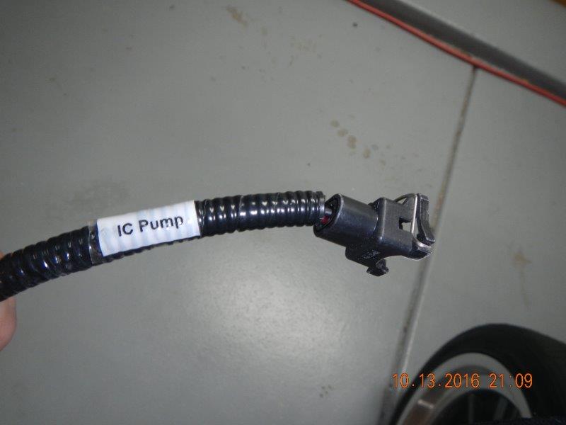

Since I already had opened up the entire Takeout BB line, it was easy to strip back the black and red wires that go to the Intercooler all the way back to the point where Takeout BB separates from the main harness set just inside the access hole through the PS of the Firewall. After carefully following the wires three times to be sure I did not cut out the wrong ones, I clipped these two wires, leaving just enough to seal the ends up.


I curled over the end of each wire, and then put a piece of heat shrink tubing over it to seal that wire. Then I but both wires together with yet one more piece of heat shrink tape to completely seal it off, and clearly mark the pair just in case they are needed in the future.

The process of eliminating the wires for the intercooler removed at least nine feet of wire from behind the firewall.
Last edited by Jazzman; 10-14-2016 at 01:43 AM.
-
10-14-2016, 02:03 AM
#418
Take out CCA is very near the main harness cable that leads from the PDB to the PCM. Takeout CCA is the one that has wires sets for four different items: The A/C Pressure wires, the A/C Clutch wires, a blunt-cut orange wire which will be routed to the cooling fan, and the Starter Lead Eyelet. After a great deal of thought and many changes of mind, I have finally decided the cost and complexity of Air Conditioning in this car is just not worth the effort. (I may live to regret that decision!!) One of the major factors in this decision is the reality that the primary producer of an AC system that is supposed to fit into the car no longer manufactures it. But I did want to retain the ability to go back and retrofit an AC system if I decide I have to have it. I decided to cut out the two leads that would go to the AC system, but leave nice, long, wires easily accessible within the primary harness. I carefully removed all the tape and wire loom from these two leads:
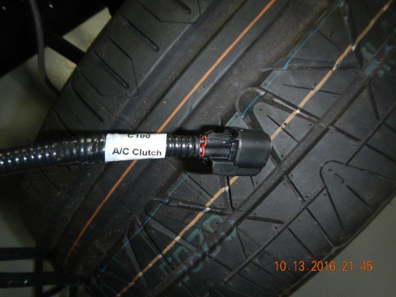
The AC Clutch wires are a pair of one black and one Purple wires.

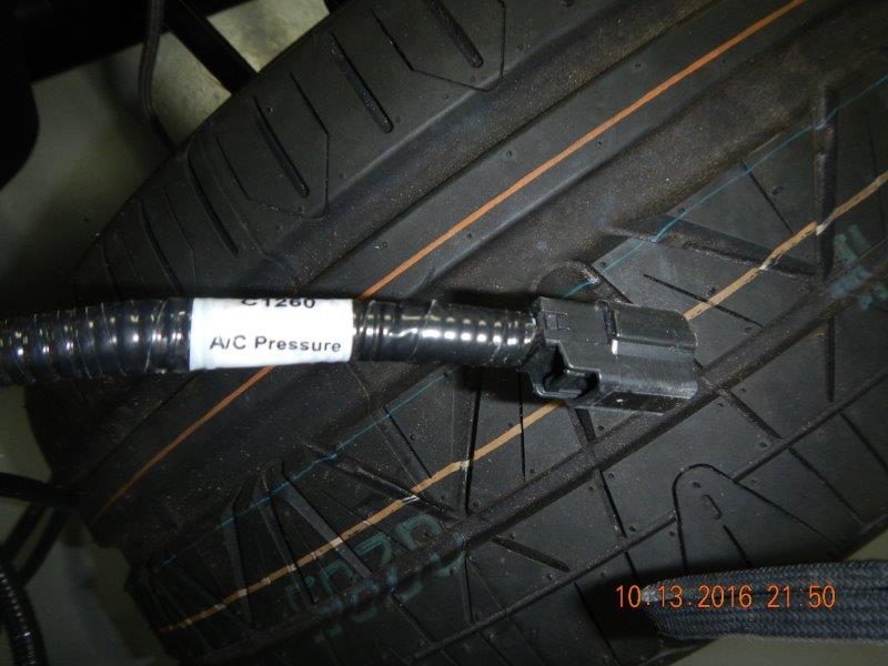
The AC Pressure wires are a trio, one grey, one yellow, and one yellow/purple.

I cut each of these wires leaving about 10" of wire attached to the plug end. I packaged up these two plugs, and marked the ziplock bag "Do Not Discard, AC Pressure and Clutch wires". I filed them away with the many other extra parts that I am accumulating. I sealed off the ends of each wire with a heat shrink tube, then grouped each set together and terminated the complete set with one more piece of heat shrink tube. I laid each wire set next to the main wiring harness to/from the PCM. Since the wires came from opposite directions, it was rather easy to lay them both into the harness set. I reopened the main wiring harness from Takeout AA back toward the PDB for about 24". (I am glad I left the main harness accessible, but I sure hope I don't have to go into this again!!) I then re-covered all the wires with the loom, this time including the AC wires hidden along the side of the main harness, but inside the loom.
While I was inside the main harness, I moved the point that the Starter lead Eyelet exits the loom. It was coming from the direction of the PDM, thus is was easy to just pull it out of the loom back to the point where it exits just forward of the front edge of the PS Footbox. This creates more wire which will be trimmed once the engine and starter are in place. It also means the this wire and loom can be run down the side or corner of the PS footbox. I would love to hide this wire, but at least I can make is less obvious.

I also move the exit point for the blunt-cut orange wire that will be connected to the cooling fan. This wire was already seemingly long enough, but this minor change added a few more useable inches in the wire. For now, this orange wire is loose, awaiting the installation of the radiator and fan.

This area of the harness is cleaned up rather nicely. Not quite done, but a big improvement.

Last edited by Jazzman; 10-14-2016 at 02:18 AM.
-
10-14-2016, 04:50 AM
#419
Senior Member
Nice work. If you choose to mount the engine ground to that engine mount in the last picture go ahead and grind the powder coat now before the engine is in the way. Makes it that much easier. The hole that is already in the side of it made for a nice location.
MK4 #8900 - complete kit - Coyote, TKO600, IRS - Delivered 6/28/16 First Start 10/6/16 Go cart - 10/16/16 Build completed - 4/26/17 - 302 days to build my 302 CI Coyote Cobra - Registered and street legal 5/17/17
Build Thread
http://thefactoryfiveforum.com/showt...e-build-thread
PHIL 4:13 INSTAGRAM - @scottsrides
-
10-15-2016, 02:02 AM
#420
-
10-17-2016, 12:00 AM
#421
Working on wiring again. I made some slow progress, some revelations, and then a big epiphany. As you read my thread, keep in mind that I am NOT using the traditional FFR wiring scheme using only the RF harness. I am biasing my wiring toward the Coyote Wiring harness. I am mirroring the wiring scheme developed by EdwardB that merges the two wiring harnesses. Loosely speaking, the Coyote harness is responsible for everything in the engine compartment, and the RF harness is responsible for everything outside of the engine compartment. I like the fact that by doing this, all of Ford's built in controls and features will work in harmony as they were designed to do. I am also doing a lot of wire loom stripping and redesign to clean up the appearance of the wire harnesses. I don't know that you have to do all this, but I am being obsessive about appearance and functionality.
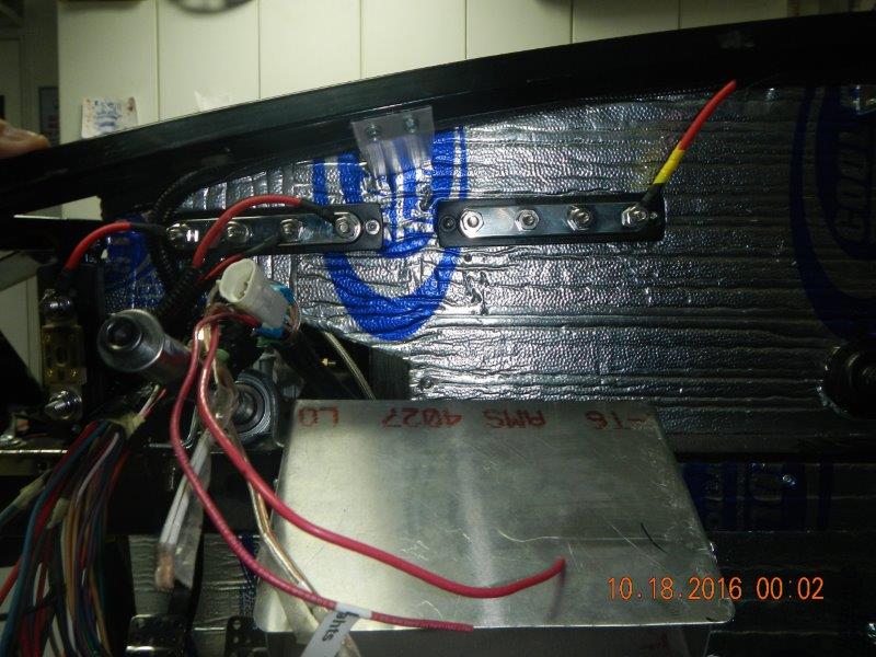
Lets start with the big epiphany first, because it had significant impact on all the work I did, and re-did, this weekend. Here is a photo of the engine compartment before the epiphany. What is wrong with this picture?

The red cable coming from the transmission tunnel terminating at the left side of the 250A Fuse is the end of the Battery positive line coming from the SWITCHED side of the Master Disconnect switch. The cable going left and down is the starter cable. The problem is this: The line going to the left side of the Master fuse should be UNSWITCHED, HAAT (Hot At All Times), but I don't have one of those in the Engine compartment. The starter cable should be coming from the SWITCHED side of the master disconnect, but it should not be on the same terminal as the Master Fuse. The Ford Coyote instructions are very clear that the power feed to the PDB must be HAAT. I came to the realization that I need two Cables coming from the Master Cutoff Switch, one Switched and one UNSwitched.
That realization required that I undo quite of bit of what I had already done. I had to disconnect, unhook, and open up the wire loom around the entire cable set going down the transmission tunnel to the rear of the car. This took quite a bit of time, but since I had been here before, I knew what to expect. To gain access, I had to remove the Master Disconnect switch from the trunk floor. As I was doing this I discovered an unexpected problem: the main power cable from the Battery Positive to the Master disconnect was so loose that the cable came out of the ring terminal! Surprisingly this was not one that I had made up. It came that way. The shrink wrap was holding it together. I decided I would make up a new cable and replace it entirely. I made a new cable, used the impact tool to crimp the end on the #4 cable, then soldered the connection. This one is not coming apart!
I used the #4 cable provided by Ford with the Coyote Wiring harness as the cable for my new Unswitched positive cable. It was long enough, the right size, and already had a Ford factory installed ring terminal on both ends. I attached the cables to the master disconnect, recovered everything with wire loom, and re-taped everything again. Because it is all black with wire loom, because it is all in shadowy areas, there really isn't much to see. It looks just like it did before, except where it comes out at the front of the transmission tunnel.

Now you can see the UNSwitched cable from the master disconnect terminating on the left side of the Master Fuse. The longer red cable without a terminal end that is looping around is the Switched cable. I have a single terminal Stud on order. When it arrives, this cable will be will be attached to the Single Terminal Stud, and the cable to the starter will also be attached to that same stud. I will also attach the "Alternator" cable from the RF harness to this same Switched Power Terminal Stud. By doing this, when the Master Disconnect Switch is turned off, power will still go to the PDB, but it will not go to the Starter or the RF harness, including most of the dashboard. (The obvious exception would be the clock and the GPS powered Speedo, which will be on a HAAT UNswitched Circuit.
I also confirmed that the center loom in the photo pointing straight down with the plug on the end is the secondary power for the PDB. (I'm not clear on why Ford needs it, but I will oblige. I cut the plug off (Not using that from the Coyote harness). The red wire will be attached on the fused side (the right side) of the master fuse, the same location that the feed line for the front terminal of the PDB comes off. The black line is another dedicated ground. It will be shortened, and then I will create a special grounding location just for it on the underside of the 2" square frame member that the PDB is attached to. This should provide a sure ground for this important piece of the power puzzle.
Last edited by Jazzman; 10-17-2016 at 12:16 AM.
-
10-17-2016, 12:01 AM
#422
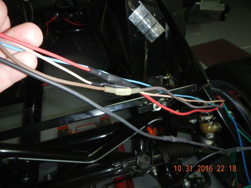
Here is the wires from the RF that are marked "Alternator". The small one is marked "ALT IGN", the larger two into the larger plug are simply marked "Alternator".

Because this line is 4-5 feet longer than I think is necessary, I stripped back all the loom around this line all the way to it's base.

I discovered there are not really two lines going to the Alternator, there is only one, "Y"ed about 10" from the plug.
I am going to run this single power cable all the way to the switched power cable from the Master disconnect.
I confirmed that using this wiring scheme, which rely's on Ford's Coyote wiring system for engine functions, The blue wire in the RF harness marked "Start Sol" can be eliminated.

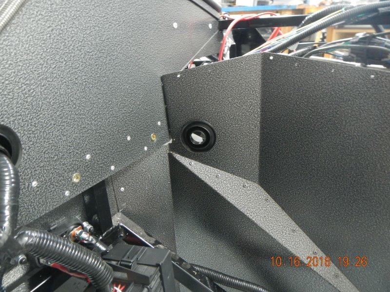
I needed to create an access hole through the inside wall of the DS footbox to allow a number of wires and the clutch Hydraulic line to pass between the engine compartment and the inside of the DS footbox. Thank God for the inventor of the RivetNut! I was able to just unscrew the PDB from its installed location to gain access to the location for the hole.

Ford was kind enough to provide two 2" rubber grommets to protect the various wires. The first was already installed on the main harness loom just to the left of the PDB, but the second one was unused. I drilled a 2" hole in the side of the DS footbox. Through this hole will pass a lot of stuff: The rear harness cables from the RF harness will go in, the sender wires from the Coyote harness will go out, The "Alternator" cable from the RF harness will go out to the Switched power stud, a similar unswitched cable will come back in from to feed power to a HAAT bus bar behind the dash, and the hydraulic line from the clutch pedal to the slave unit on the transmission will go out. This should make that area an even more busy place!!
Last edited by Jazzman; 10-17-2016 at 12:23 AM.
-
10-18-2016, 04:26 PM
#423
The ANL fuse block that I had ordered from DelCity did not come in the primary shipment. I had just about decided that they had forgotten to send it when it showed up on my doorstep.
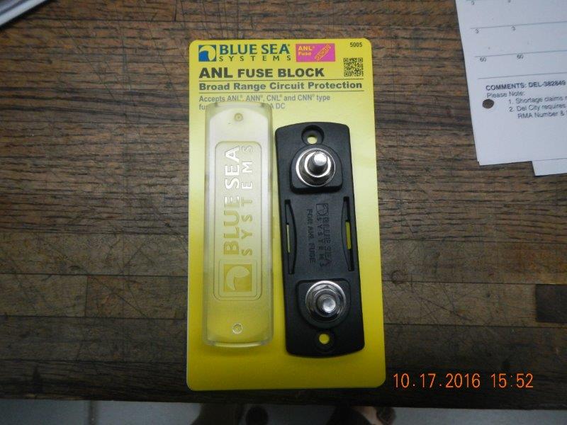
Installation was quick and easy, although I could not use rivets to attach it. I went ahead and used sheet metal screws for this. I will keep an eye on it to see if it begins to come loose, but it seems quite solid.

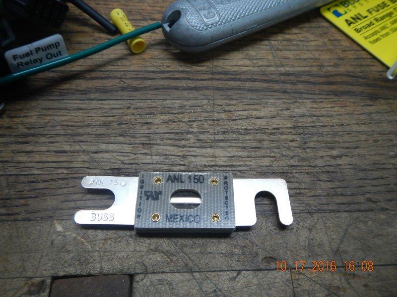
The 150A fuse separating the feed from the Alternator from the RF harness and the Coyote PCM and PDB has two distinct ends. It is sort of hard to see in the photo, but one side is marked "Ignition" and the other is marked "Protected. The feed line from the Alternator to this 150a fuse will be attached to the lower stud of this bus bar. Because I consider the alternator to be the "Hot"/"ignition" side, and I am trying to "protect" the RF harness, I installed the fuse with the opening at the end to the bottom stud, and the one that has a sideways opening will be attached to the top of the fuse block.

Included with the fuse and block from DelCity was the remaining supply of cable terminals. I had been waiting for cable ends with a 90 degree bend in them. I found that the 90 degree terminal was just a bit too short to fit over the front stud on the PDB. I relieved it by opening the terminal to about a 75 degree angle. Now it fits fine.

I made the 3" long jumper to go from the top stud of the Alternator fuse to the switched buss bar. A piece of left over cable, a 1/4" ring terminal, a bit of solder and shrink wrap, and it is ready to go.

Here you can see it connected. (Got my focus point a bit off, sorry!)

Though not installed yet, the main power cable from the Alternator to the Alternator fuse will be attached to the lower stud on this fuse block.
Last edited by Jazzman; 10-18-2016 at 04:58 PM.
-
10-18-2016, 04:53 PM
#424
I think I am glad that the area where all these cables come together is mostly hidden behind the engine below the firewall. It has become very busy in this area. I found that Ford had kindly provided me a single stud terminal point. (I will have to return the one I just ordered.)

I installed it to the left of the main fuse block. Then I started attaching all the cables where they needed to go. There is so much movement there, it is beginning to look like a freeway interchange! On the photo, below, I decided to number the runs to make it clearer what is going on:

1. Main UNSwitched cable from the master cutoff switch in the trunk.
2. Main Switched cable from the master cutoff switch in the trunk.
3. Starter cable from the Switched Terminal stud down to the Starter. (When the master cutoff switch is turned off, there is no power to the starter cable.)
4. Secondary power cable to the PCM and PDB. This single wire branches off the bottom of the main Coyote wire harness and is attached to the switched side (right side) of the 250A Master fuse. (This will remain HAAT as long as there is a battery in the car. This is connected in the photo, but I am leaving it disconnected during the wiring phase so as not to accidentally fry the PDB or the PCM!) There is a small black wire coming off of this same point going left. This is a dedicated ground wire for the PCM/PDB. I attached it on the underside of the 2" frame member where it will not be seen.
5. the "Alternator" cable from the RF harness that goes back to feed positive power to the RF fuse panel and the Switched Fuse Panel. This is attached to the Switched terminal stud. (Master Cutoff switch turned off, no power to the RF harness.)
6. HAAT cable feeding power to the new HAAT Bus Bar (photo to follow) This power will remain on regardless of Master Cutoff switch position. It will feed the GPS Speedometer memory, the clock, the USB plugs, etc.
7. Main #4 Power cable to feed power to the PDB. (This is connected in the photo, but I am leaving it disconnected during the wiring phase so as no to accidentally fry the PDB or the PCM!)
8. Rear wiring harness going up to the opening and grommet in the sidewall of the DS footbox.
Item #6 referenced a new HAAT bus bar. Amazon screwed up by the numbers on these bus bars, and, long story short, I ended up with two of them for free. I did have to call Blue Sea Systems to have them send the plastic isolation covers, but they sent them for free, so all is good. I decided to go ahead and use the second bar just to make it easier for me to identify and service each circuit.
Last edited by Jazzman; 10-18-2016 at 04:57 PM.
-
10-19-2016, 06:25 AM
#425
Senior Member

Regarding your #6 (HAAT bus bar) for you and others reading this thread, you are aware the Coyote pigtail harness has a HAAT connection available? That is what I used for the clock, GPS, etc. Advantages are it's routed inside the cockpit already from the Coyote harness that has to be there. Plus 1already fused in the PDB. Your approach will certainly work. But there is another option.
Build 1: Mk3 Roadster #5125. Sold 11/08/2014.
Build 2: Mk4 Roadster #7750. Sold 04/10/2017.
Build Thread
Build 3: Mk4 Roadster 20th Anniversary #8674. Sold 09/07/2020.
Build Thread and
Video.
Build 4: Gen 3 Type 65 Coupe #59. Gen 3 Coyote. Legal 03/04/2020.
Build Thread and
Video
Build 5: 35 Hot Rod Truck #138. LS3 and 4L65E auto. Rcvd 01/05/2021. Legal 04/20/2023.
Build Thread. Sold 11/9/2023.
-
11-03-2016, 03:16 AM
#426
Wiring - AKA "Intimidation 101"!
Aloha, Friends! For the past two weeks, I have had the joy of going to the garden Isle of Kauai, Hawaii. I decided that my long-suffering and extremely wonderful bride had waited long enough to return to one of our favorite places. The opportunity arose to go on relatively short notice, and we decided to jump at it. Here is just one of the photos I took of the amazing views that we enjoyed:

We had a wonderful time. Most of it was spent enjoying the many opportunities in paradise, but we did get some rain while we were there, so I used the down time to order parts and re-read build threads. There is an amazing amount of information that I had forgotten. It actually was a lot of fun re-reading some of my favorite threads. Even now, I am gleaning new information.
You may remember that about a month ago I returned the Quicktime Bell housing that had been purchased with my engine because it turns out that I must use #6081 because the flange is smaller and fits correctly. I was told, "no problem, we will get the correct one for you". I had expected to wait a week or so to get then new one, but one week stretched into two. When I still did not have it before we were leaving for vacation, I told the vendor that I must have it on 10/31 or I would expect a refund. He said "No problem, we will have it by then". (You already know where this is going.) I arrived Monday to pick it up, and no, he still did not have it, in fact he had not even returned the incorrect item. Long story short, it got rather heated. I finally asked him to call the manufacturer so I could find out what the holdup was. It took a few phone calls, but we finally got through to a person that would take action and get this problem fixed. So theoretically I should have the correct bell housing by the beginning of next week. I am not holding my breath . . . (I am also no longer recommending this vendor.) A month is simply too long to have to wait for a replacement part.
Once I had recovered from two weeks away from the office, I was finally able to get back to the wiring process. It took me quite a while to figure out where I had stopped. I am still re-adjusting where the wire bundles separate out. I returned to the front wiring harness. The PS light wires separated from the DS light wires right in the middle of where the radiator will be. I unbundled the front harness and carefully moved the separation point to the DS. I had to cut and splice several of the wires in order to move the separation point. I am finding that the crimp and shrink butt connectors I ordered work very well.
While I will not be using the wires for the fan and the fan thermostat, I am leaving them in the harness because I am going to use them for different purposes. The larger fan wire will be used for the Tangent driving lights that I have yet to order, and the Fan Thermo wire will be used to feed the LED lights that will be mounted inside the engine compartment. I am still researching to determine it the wires are adequate size for these loads. Because of this I have not yet closed up all the convolute covering.
I realized after it was all done and put back together that I had forgotten to include a wire for the PS engine compartment lights going over to the PS. So I will have to open it up again. Oh well, one more item for the list.
-
11-03-2016, 03:41 AM
#427
Tonight I continued trying to figure out what the second wire going to the starter is connected to. In all my research, there are two wires going to the starter: the large 12 volt #4 cable carrying power directly from the battery, and a smaller wire that signals the starter to start. My problem was I couldn't figure out where the other end of this starter signal wire was connected. After an inordinately long period of time re-reading all the wiring notes, emails, instructions, and other info I could fine, I finally was reminded that the signal wire is a blue wire that comes out of the Coyote wiring harness. I know I have seen and moved that wire a dozen times, but it didn't sink in until now. I finally realized I didn't need the wire I had put inside the convolute with the battery cable. I removed that wire, then realized that it would be much cleaner if I moved the location of where this starter signal wire exits the primary Coyote convolute cable. This blue wire is the starter signal wire. I moved it back in the harness so that it exits just above where the battery cable goes down to the starter.

Once I had decided to open up this wiring harness again, I re-evaluated the harness that I had previously routed inside firewall behind the dash. Remember this take out:
I decided I could move it back even further toward the center of the firewall and take it out behind the engine. After stripping the main cable all the way back to the PDB, I re-taped up the harness and ended up with this configuration. First, this takeout has been eliminated at that location:

Now all the wires for the MAF sensor and the Alternator signal wire exit the main harness just to the PS of the access hole and grommet through the firewall. Once the engine is in, I will be able trim these two sets of wires to fit over the top of the engine underneath the engine cover.

I think this particular section of harness reconstruction is about done. I hope so, because I went ahead and wrapped all the convolute in the engine bay with tape and mounted the wire harness clamps to hold it in place.

I hope I don't come to regret that decision!!
-
11-03-2016, 04:48 AM
#428
Senior Member
Welcome home and glad to see you back at it. Can't believe they hadn't even returned the bellhousing yet and got your replacement. I would have been hot as well.
While you are looking at wire locations I had one extra pop up at the end you may want to think about. The wire for the GPS antenna for the speedo needs to go somewhere. Look in your gauge box. The GPS antenna is about 1 1/2" square and magnetic. I ended up placing it on the top of the PS windshield mounting location and running the wire through the hole in the 2nd picture of your last post. Not sure if that area would be visible with the flip top so just wanted to give you a heads up.
MK4 #8900 - complete kit - Coyote, TKO600, IRS - Delivered 6/28/16 First Start 10/6/16 Go cart - 10/16/16 Build completed - 4/26/17 - 302 days to build my 302 CI Coyote Cobra - Registered and street legal 5/17/17
Build Thread
http://thefactoryfiveforum.com/showt...e-build-thread
PHIL 4:13 INSTAGRAM - @scottsrides
-
11-03-2016, 05:55 AM
#429
Senior Member
Welcome back! Tough duty in Hawaii.  Three quick points based on your recent wiring posts. If you decide to go with the Tangent driving lights, and you use the light fixtures provided, you actually need two power wires. The unused RF fan wire would be more than adequate for the higher capacity bulbs. Good idea. You'll need a second wire if you want to separately light the smaller bulbs in the fixtures. I'm not quite understanding your description of the starter wires. If you're using the Coyote harness, PDB, PCM, etc. to control the start process, you only need the pictured Coyote Starter Lead (the labeled one in the braided insulation) and the +12V large battery lead. That's it. The blue wire pictured, I assume from the RF harness, is not used. That entire RF leg, from the ignition switch and going through the clutch safety switch, is not used if the Coyote is controlling the start. Finally, looks like you're taking the front harness across the top of the radiator area? Maybe that's because of your tilt front mod? Usually that leg goes across the bottom of the radiator and the harness split is in the right place. Wiring is fun, isn't it? You're making good progress.
Build 1: Mk3 Roadster #5125. Sold 11/08/2014.
Build 2: Mk4 Roadster #7750. Sold 04/10/2017.
Build Thread
Build 3: Mk4 Roadster 20th Anniversary #8674. Sold 09/07/2020.
Build Thread and
Video.
Build 4: Gen 3 Type 65 Coupe #59. Gen 3 Coyote. Legal 03/04/2020.
Build Thread and
Video
Build 5: 35 Hot Rod Truck #138. LS3 and 4L65E auto. Rcvd 01/05/2021. Legal 04/20/2023.
Build Thread. Sold 11/9/2023.
-
11-03-2016, 07:48 AM
#430
Senior Member

This is such a gutsy build. But you pulled it off. Fantastic job.
-
11-04-2016, 12:52 AM
#431
Originally Posted by
2FAST4U
This is such a gutsy build. But you pulled it off. Fantastic job.
Thanks! It ain't done yet, but it will be!! Slow and steady. I am so appreciative for all the help I have received from members of the forum. It is not too strong to say that I literally could not have done this build with out the support of the members of this forum. Thanks to all!!
-
11-04-2016, 01:29 AM
#432
Originally Posted by
edwardb
I'm not quite understanding your description of the starter wires. If you're using the Coyote harness, PDB, PCM, etc. to control the start process, you only need the pictured Coyote Starter Lead (the labeled one in the braided insulation) and the +12V large battery lead. That's it. The blue wire pictured, I assume from the RF harness, is not used. That entire RF leg, from the ignition switch and going through the clutch safety switch, is not used if the Coyote is controlling the start. Finally, looks like you're taking the front harness across the top of the radiator area? Maybe that's because of your tilt front mod? Usually that leg goes across the bottom of the radiator and the harness split is in the right place. Wiring is fun, isn't it? You're making good progress.
As usual, you are right. I was trying to make the starter wiring much more complex than it needs to be. I won't rehash the details and potentially confuse a future reader, but I was trying to find a wire from the RF harness that would connect to the starter. When allowing the Coyote PCB and PCM to control everything, there is no RF starter signal wire that needs to be connected to the starter. Bottom line: I had done a good job of marking and organizing the Coyote starter wire, then forgot all about it. When I finally spotted it, It finally dawned on me that the blue starter wire from the Coyote harness was the only thing needed. I'm slow, but I do catch on!! Thanks for the confirmation that I am back on the right track.
You are right, I am taking the front light harness across the top rather than down below as is usual. Because of the movement of the flip top, and the modifications in the area of the lower radiator, it seems to be a bit more simple to take it across the top. I plan to hook the smaller bulbs in the Tangent fixture into the running light circuit since they are more decorative in nature.
-
11-04-2016, 05:36 AM
#433
Senior Member
Originally Posted by
Jazzman
I plan to hook the smaller bulbs in the Tangent fixture into the running light circuit since they are more decorative in nature.
Great idea! Wish I had thought of that. 
Build 1: Mk3 Roadster #5125. Sold 11/08/2014.
Build 2: Mk4 Roadster #7750. Sold 04/10/2017.
Build Thread
Build 3: Mk4 Roadster 20th Anniversary #8674. Sold 09/07/2020.
Build Thread and
Video.
Build 4: Gen 3 Type 65 Coupe #59. Gen 3 Coyote. Legal 03/04/2020.
Build Thread and
Video
Build 5: 35 Hot Rod Truck #138. LS3 and 4L65E auto. Rcvd 01/05/2021. Legal 04/20/2023.
Build Thread. Sold 11/9/2023.
-
11-08-2016, 02:53 AM
#434
I am filling in with small projects while I wait for the bell housing to arrive. I am into week six waiting for it to be replaced and my patience is growing thin!! I began working on the PCV and vacuum system modifications that are well documented in this thread:
http://thefactoryfiveforum.com/showt...-CMCV-Plumbing
If you are installing a Coyote, I highly recommend reading this thread. I will only add my own observations to this well documented thread.
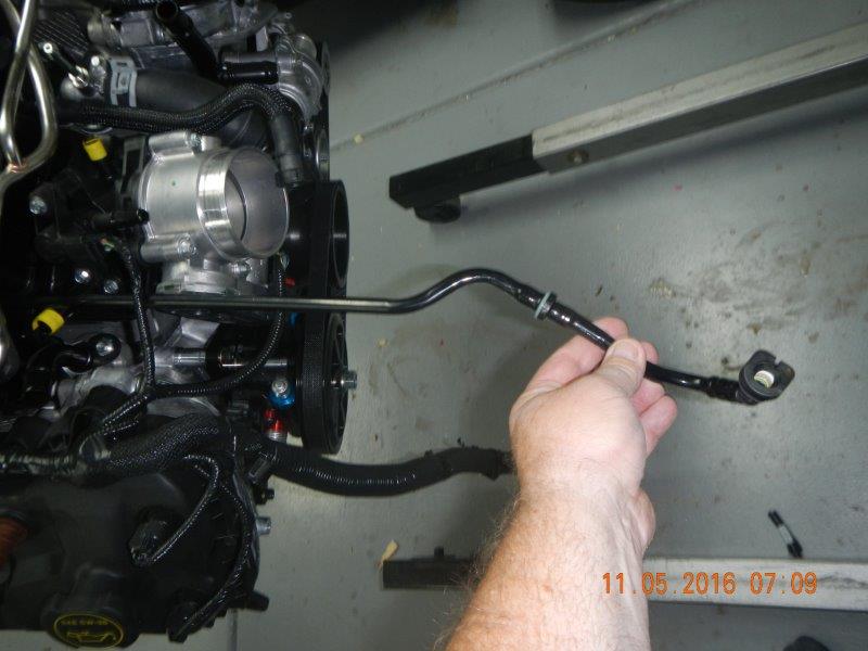
First I had to disconnect the vacuum line from the back of the engine. This little sucker packs a lot of frustration power!!

The clamp that holds it onto the engine is a dual clamp design. I am sure that there must be a tool to remove these easily, but without that tool, it is quite a job. release one clamp, the other still holds the hose tight. Release the other, same problem. It put up a good fight, but I finally got the clamp off.

Now the rubber hose is still very tightly attached. I finally gave up on that one and just cut it off.

I'm sure it was in the documentation somewhere, but I didn't pick up on the fact that there were two vacuum lines going to the air intake, one running up each side of the space under the air plenum. After consultation with the real experts, It became clear to me that when you disconnect the 90 degree hose at the back of the engine, you inherently disconnect the line that runs up the PS of the plenum. This can be removed completely.
EdwardB put together a very nice parts list to do his modification. When I purchased my complete kit, I purchased the "Coyote Fitment Package". One of the boxes had a bunch of hoses and clamps for the engine. I found this hose, and realized it was for the vacuum system, and it fit the front vacuum port that Edwardb shows us to use.

I decided to see what else was in the box that I could use. I found that with a little creativity, I didn't need to buy anything to complete the vacuum system modifications. I found a 1/2" T fitting and a barbed fitting for the smallest vacuum line that will go to the fuel regulator.


Last edited by Jazzman; 11-08-2016 at 02:56 AM.
-
11-08-2016, 03:15 AM
#435
-
11-08-2016, 03:53 AM
#436
Moving back to wiring, I installed the Computer access port. because everything else was on the DS, I put this way over on the PS, out of the way but still accessible.

This did, of course, required yet more stripping of the wiring harness and reworking the wire exit locations. I have pretty much stripped every branch of the RF wiring harness now. It is slowly getting done and becoming more organized. The three main wires needed to be shortened, and I will connect the two ground wires to the frame with the other main grounding leg of the coyote harness.

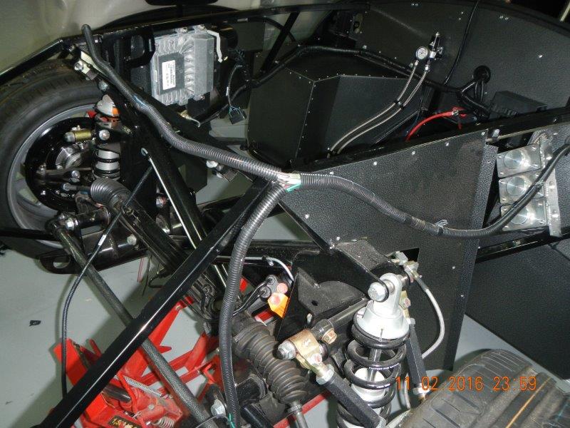
I ran buttoned up the main battery line to the starter and the blue Coyote start wire and ran it down the angled engine bay support member. It is well out of the way, yet provides enough flexibility reach the starter. (I hope!!) I made up the alternator line to go from the Alternator to the fuse bar behind the dash. It is not yet cut to length, I will do that after the engine is installed. Everything now appears to be ready to install the engine. Nothing is in the way, and I think all the wires and harnesses are in place, ready to go.
I found that after stripping the APPS line (Accelerator Pedal Power Supply), then putting it in its own convolute line, It was just the right length to go to the Accellerator pedal area. Nice that I didn't have to splice this one at all.

-
11-08-2016, 04:15 AM
#437
-
11-08-2016, 06:45 AM
#438
Senior Member
Keep in mind that line to the alternator also can be combined with the tach wire, oil pressure and water temp senders that hook up down by the alternator. Can't help you on the master cylinders because mine are different.
What is eta on the bell housing?
MK4 #8900 - complete kit - Coyote, TKO600, IRS - Delivered 6/28/16 First Start 10/6/16 Go cart - 10/16/16 Build completed - 4/26/17 - 302 days to build my 302 CI Coyote Cobra - Registered and street legal 5/17/17
Build Thread
http://thefactoryfiveforum.com/showt...e-build-thread
PHIL 4:13 INSTAGRAM - @scottsrides
-
11-08-2016, 08:58 AM
#439
There are two ways to screw the shafts in and out but the easiest will be to pull the boots off the master cylinders. Then boot and shaft can turn together. When you get the pedal adjusted, the boots can be pushed back on the masters. The other is to turn the shafts with boots attached but that is more difficult. The shafts will spin in the boots with something like needle nose pliers applying the turning force but that is slow going.
-
11-12-2016, 01:34 AM
#440
I am moving ever closer to engine install. I spent most of this week trying to figure out the finer points of the clutch fork. After consultation with other members of this forum, I began this evening putting the fork into the bell housing. I put the throwout bearing onto the fork, and very lightly greased all the contact surfaces.
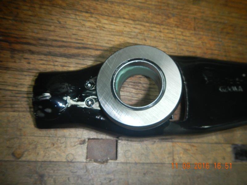
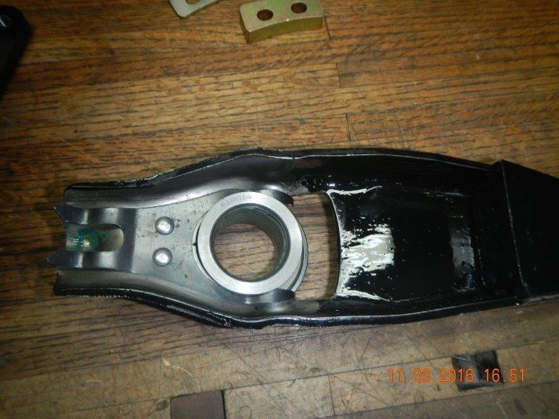
At the far right side of the previous photo, you can just barely see the fork weight. This is not needed with the hydraulic clutch setup I am doing. I removed it, but forgot to take another photo. Imagine the clutch fork with a big empty spot on the back. Ok, you've got it!!
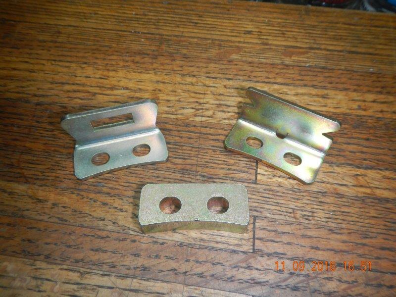
It took me quite a while to determine that these three pieces are not needed in this particular setup.
I attached the aluminum attachment piece from the Forte Hydraulic clutch kit to the end of the clutch fork. It comes with one bolt, but like EdwardB, I decided to add a second one. Not really sure if it is necessary, but nature abhors a vacuum, and there was a second hole in the piece that was just begging to be filled. I gave the entire fork two coats of POR15 to seal it up and make it look good. (like anyone but you is actually going to see it under there!!)


Make note that in that photo, the attachment piece is actually too far out. I had to adjust it further back on the clutch fork. I just about lined up the fronts of each piece. Your adjustment may vary!
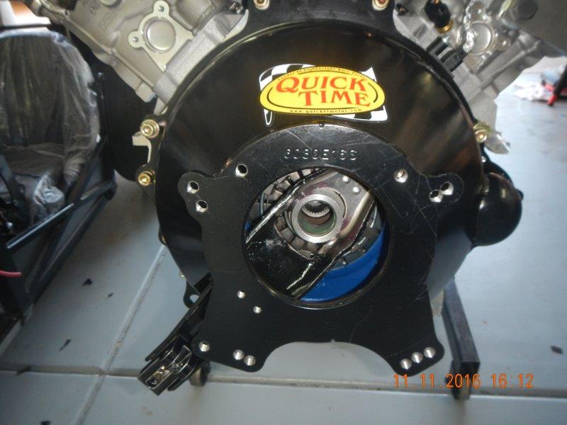
I installed the bell housing (finally!!!). I had to open up the PS alignment hole on the bell just a bit to make is slip on smoothly. I used the die grinder and a narrow grinding bit to remove the black paint/powdercoat from the inside of the hole, then removed just a little bit more. After a couple of attempts, it slipped on easily. The bolts are generally straightforward. Five equal length bolts go into the holes on the sides of the bell, the two longer bolts and the unique spacers that come with the bell go over the top of the two alignment pins. Because one pin is so close to the side of the bell, only one of the spacers will work in that place. The spacer with the offset hole goes over the PS alignment pin, the centered hole spacer goes over the DS alignment pin. Used blue loctite on everything, but all these bell attachment bolts also have lock washers. I used both. Could not find torque values anywhere, so I tightened them "sufficiently". At the bottom of the bell, offset from center, are two smaller threaded holes in the bell. The bell bolt kit comes with two 1/2" long bolts that are installed from the front side of the mid plate into the flange on the bell housing.
 Posting Permissions
- You may not post new threads
- You may not post replies
- You may not post attachments
- You may not edit your posts
-
Forum Rules

Visit our community sponsor


 Reply With Quote

