Very Cool Parts

Visit our community sponsor

Thanks Thanks:  29
Likes Likes:  38
Page 7 of 20 FirstFirst ... 5678917 ... LastLast
Results 241 to 280 of 779

Thread: EdwardBs Mk4 #8674 20th Anniversary Build

  1. #241

    Steve >> aka: GoDadGo
    GoDadGo's Avatar
    Join Date
    Feb 2015
    Location
    Slidell, Louisiana
    Posts
    6,567
    Post Thanks / Like
    Blog Entries
    1
    I Wish I Had Your Skills! My MK-4 is coming along nicely, but not this nicely! Keep it up because you are helping everybody by showing us what a Factory Five can be. Can't Wait To See The Final Product!

    PS: How do you like your Max Jax Lift?

  2. #242
    Senior Member edwardb's Avatar
    Join Date
    Feb 2011
    Location
    Lake Orion, Michigan
    Posts
    10,567
    Post Thanks / Like
    Quote Originally Posted by GoDadGo View Post
    I Wish I Had Your Skills! My MK-4 is coming along nicely, but not this nicely! Keep it up because you are helping everybody by showing us what a Factory Five can be. Can't Wait To See The Final Product!

    PS: How do you like your Max Jax Lift?
    Thanks for the generous comment. I'm anxious to see and drive the final product as well. But I also enjoy the build process.

    The MaxJax? It's exactly what it is. A relatively basic DIY quality lift. I wouldn't compare it directly to a more professional version, but then it's much cheaper and fits better into my 2-car garage. It's perfect for the low ceiling garage I have. I can't go any higher than this will go. My only complaint is the two posts don't always stay perfectly synchronized. But it's not a big issue and completely workable. The difference in working on the build on a lift vs. the usual jack stands and crawling on the ground is night and day.
    Build 1: Mk3 Roadster #5125. Sold 11/08/2014. Build 2: Mk4 Roadster #7750. Sold 04/10/2017. Build Thread
    Build 3: Mk4 Roadster 20th Anniversary #8674. Sold 09/07/2020. Build Thread and Video. Build 4: Gen 3 Type 65 Coupe #59. Gen 3 Coyote. Legal 03/04/2020. Build Thread and Video
    Build 5: 35 Hot Rod Truck #138. LS3 and 4L65E auto. Rcvd 01/05/2021. Legal 04/20/2023. Build Thread. Sold 11/9/2023.

  3. #243

    Steve >> aka: GoDadGo
    GoDadGo's Avatar
    Join Date
    Feb 2015
    Location
    Slidell, Louisiana
    Posts
    6,567
    Post Thanks / Like
    Blog Entries
    1
    1. Right now I use floor jacks, blocks, jack stands and my purpose built Factory Five Super Saw Horses (See My Gallery) so you get the picture.
    2 If the Max Jax system would be installed permanently, basically hard lining the hoses at equal length, do you think they would stay in sync since it uses a positive displacement style pump?
    3. Also, I too have a low ceiling (8'6") so the lower lift height (42") is actually perfect for my needs.
    4. What-Cha-Think about hard lining and permanently mounting the system if you don't need to move it around?
    Last edited by GoDadGo; 04-01-2016 at 05:24 PM.

  4. #244
    Senior Member edwardb's Avatar
    Join Date
    Feb 2011
    Location
    Lake Orion, Michigan
    Posts
    10,567
    Post Thanks / Like
    Quote Originally Posted by GoDadGo View Post
    1. Right now I use floor jacks, blocks, jack stands and my purpose built Factory Five Super Saw Horses (See My Gallery) so you get the picture.
    2 If the Max Jax system would be installed permanently, basically hard lining the hoses at equal length, do you think they would stay in sync since it uses a positive displacement style pump?
    3. Also, I too have a low ceiling (8'6") so the lower lift height (42") is actually perfect for my needs.
    4. What-Cha-Think about hard lining and permanently mounting the system if you don't need to move it around?
    Yea, I know about all that. Did two builds that way and promised myself I wasn't going to do it again. My tired body just couldn't take it any more. The MaxJax flexible hoses are already the same length, and I don't think hard lines or a permanent installation would change how it operates. For me it's important to keep it portable. When I don't have a project on the lift, I unbolt the post in the center of the garage and roll it over to the other wall. It just takes a few minutes and for me is a major advantage of this particular setup. I don't consider the sync thing to be a major issue. It's just a function of the very simple design. But I wanted to point it out in my comments for full disclosure. If you look at reviews for this lift on the Garage Journal Board, you'll see a number of comments about how it works and this aspect is discussed frequently.
    Build 1: Mk3 Roadster #5125. Sold 11/08/2014. Build 2: Mk4 Roadster #7750. Sold 04/10/2017. Build Thread
    Build 3: Mk4 Roadster 20th Anniversary #8674. Sold 09/07/2020. Build Thread and Video. Build 4: Gen 3 Type 65 Coupe #59. Gen 3 Coyote. Legal 03/04/2020. Build Thread and Video
    Build 5: 35 Hot Rod Truck #138. LS3 and 4L65E auto. Rcvd 01/05/2021. Legal 04/20/2023. Build Thread. Sold 11/9/2023.

  5. #245

    Steve >> aka: GoDadGo
    GoDadGo's Avatar
    Join Date
    Feb 2015
    Location
    Slidell, Louisiana
    Posts
    6,567
    Post Thanks / Like
    Blog Entries
    1
    Thanks & I'll be looking to upgrade my garage in the future. Will likely go with the Max Jax system and mount it permanently since I actually built the shop in order to build the car. My other workshop washed away with Katrina so this one can be opened on both ends to let storm surges go through. Thanks For The Insight Because Crawling Around Sometimes Isn't Always That Much Fun!

  6. #246
    Senior Member edwardb's Avatar
    Join Date
    Feb 2011
    Location
    Lake Orion, Michigan
    Posts
    10,567
    Post Thanks / Like

    Dash and Wiring Harness Underway

    Today it starts in earnest. Yes, all this stuff eventually fits. But easy to see why some builders get intimidated by it. This is the regular RF harness plus the Coyote harness. There will be some pruning. Depending on how you lay out your dash, it can really help. In this case, because of where I have the ignition and headlight switches, shortening those legs off the harness helps a bunch. I'm also thinking I'm going to need to modify the Coyote harness some. Right now, everything routes to the DS footbox. But there's only so much room in there.


    Build 1: Mk3 Roadster #5125. Sold 11/08/2014. Build 2: Mk4 Roadster #7750. Sold 04/10/2017. Build Thread
    Build 3: Mk4 Roadster 20th Anniversary #8674. Sold 09/07/2020. Build Thread and Video. Build 4: Gen 3 Type 65 Coupe #59. Gen 3 Coyote. Legal 03/04/2020. Build Thread and Video
    Build 5: 35 Hot Rod Truck #138. LS3 and 4L65E auto. Rcvd 01/05/2021. Legal 04/20/2023. Build Thread. Sold 11/9/2023.

  7. #247

    Steve >> aka: GoDadGo
    GoDadGo's Avatar
    Join Date
    Feb 2015
    Location
    Slidell, Louisiana
    Posts
    6,567
    Post Thanks / Like
    Blog Entries
    1
    Ironically I just finished the chassis harness and stereo so I'm moving on to the dash so thanks for posting these pics.
    Even though the instructions that came with the kit from Factory Five / Ron Francis are good, seeing this picture really helps.
    Being a first time builder seeing this photo is helpful.
    Thanks-O-Million!
    Last edited by GoDadGo; 04-02-2016 at 11:39 AM.

  8. #248
    Member dougski's Avatar
    Join Date
    Dec 2014
    Location
    San Luis Obispo, California
    Posts
    53
    Post Thanks / Like

    Mounting trans cover

    Just curious about plans for attaching the trans cover. I read in an earlier post that you plan to make it removable. As always thanks for the exceptional level of detail in your thread.
    Mk4 Roadster #8567, IRS, Levy Racing 427w Stroker, 8-stack EFI

  9. #249
    Senior Member edwardb's Avatar
    Join Date
    Feb 2011
    Location
    Lake Orion, Michigan
    Posts
    10,567
    Post Thanks / Like
    Quote Originally Posted by dougski View Post
    Just curious about plans for attaching the trans cover. I read in an earlier post that you plan to make it removable. As always thanks for the exceptional level of detail in your thread.
    You're welcome. Regarding the removable trans cover, I don't know. My last two builds I mounted them permanently, so no experience having one that's removable. I would prefer not having visible mounting screws, so I'm thinking about some kind of hidden attachment from the bottom. But at this point don't know the details or feasibility. First order of business is to get the engine and trans in. Should be the next month or (hopefully) less. That will let me set the shifter location in the cover plus look at ways to attach it. It will have the same 1/8 foam and leather as the dash on the top, and insulation (more Lizard Skin) on the bottom. I'll post about it when the time comes.
    Build 1: Mk3 Roadster #5125. Sold 11/08/2014. Build 2: Mk4 Roadster #7750. Sold 04/10/2017. Build Thread
    Build 3: Mk4 Roadster 20th Anniversary #8674. Sold 09/07/2020. Build Thread and Video. Build 4: Gen 3 Type 65 Coupe #59. Gen 3 Coyote. Legal 03/04/2020. Build Thread and Video
    Build 5: 35 Hot Rod Truck #138. LS3 and 4L65E auto. Rcvd 01/05/2021. Legal 04/20/2023. Build Thread. Sold 11/9/2023.

  10. #250
    Senior Member edwardb's Avatar
    Join Date
    Feb 2011
    Location
    Lake Orion, Michigan
    Posts
    10,567
    Post Thanks / Like

    Clutch Switches, Wiring, Tires

    The 2015 Coyote controls pack has two clutch switches – one for the top and one for the bottom – as described in previous updates. The Ford provided switches are obviously made to snap into a production vehicle pedal box, and unwieldy to say the least for the Wilwood pedal box. The most challenging I think is the bottom switch, and I had not come up with any good ideas until a post from another forum member grluisi150. He took an approach I never considered, and it works great. Involves using the Ford provided switch, mounting it next to the clutch MC, and actuating the switch with a tab added to the MC. Note this is only applicable if you’re doing a hydraulic clutch. Yesterday I completed the fabrication, threw some paint on it, and this morning finished the installation. Works great!

    I made the mounting plate from .090 aluminum. My first version just used the rear pedal box mounting bolt, but I wasn't satisfied it wouldn't turn. So rather than drill another hole through the pedal box I made another slightly longer plate and used both pedal box bolts. Also rather than trying to use the mounting clips molded into the switch, I cut those off and used a couple of cap screws through some existing holes in the switch. I tapped some threads into the base, but since it was only .090 thick (and only aluminum) wasn't happy with only two turns on the threads. So I riveted on another little piece that gives more threads plus provides a pocket for the switch to fit into. The switch mounting seems very solid. This is in an area in the footbox that wouldn't be very friendly to service once everything is closed up, so getting it right the first time is pretty important. The actuator piece for the MC pushrod is 1/8 steel strip stock.


    All painted with Eastwood Extreme Chassis Black (good stuff) and mounted. The lead from the Coyote controls pack isn't seated yet. Just checking (and adjusting...) the length.


    This is with the clutch pedal all the way against the back of the footbox. There's still about 1/32 inch of travel left on the switch, so it's not bottoming out. I put a test light on the leads, and the switch closes with the clutch pedal about 1-1/2 inches from the back of the footbox. Perfect.


    Based on feedback from other builders using the 2015 Coyote, and indirectly from Ford Racing, the purpose of this switch is only to prevent the engine from starting unless the clutch is pushed in. So installed like this it will do exactly that. The top switch is apparently part of the solution to prevent stalling at idle so it doesn't need the speed dial module like the previous version. For that I'm using a brake light style switch for the clutch pedal arm mounted in the pedal box just like FF shows for the brake pedal arm.

    In the meantime, wiring continues. I’ve now stripped off most of the wrap and convolute on the provided Coyote harness that is through the dash. It’s just going to work better after adjusting some of the lengths and reconfiguring it a bit. As delivered, nearly everything was on the end by the DS footbox. With the bulk of the RF harness in the same area, was just too congested. So I’m adjusting it a bit. Looks worse before it gets better, right?


    Another decision for this build has been tires for the 18 inch rims. The choices are somewhat limited, but after looking them over had pretty much decided to go with BFGoodrich Rival S tires. After hearing the supply is somewhat limited and 2016 production hasn’t started yet, decided I should snap up a set. They were available at Tire Rack, so clicked the order button yesterday. The fronts showed up on my porch today. Come on Tire Rack. 20 hours from order to receipt? You’re slacking. The rears shipped from Connecticut, and are due here tomorrow. The rears are the customary 315/30’s. For the front, the choice was 245/40 or 275/35. After studying the dimensions, decided to go with the 245’s. On paper they looked very close in size to the 255/40 Nitto NT555 Extreme ZR’s on #7750. And those go right to the wheel well lip. The 275’s would have stuck out quite a bit. I took a couple of quick pics of the new front tires. It’s a little hard to tell, but they are only fractions of an inch different than the Nitto’s I have now. I’m also seeing the Rivals are not directional like the Nitto’s. Interesting.


    Certainly can see the very low profile of the 18-inch tires. Not a huge difference from the 17-inch tires, but all you 15-inch tire guys are probably cringing. It’s a different look, that’s for sure. Also evident from this picture is that good old #7750 is back in the house. I retrieved it from our off-site storage bay yesterday after its winter hibernation. It wasn’t real excited to start after sitting since late October, but it’s fine now. After checking everything over, took it for a 5 mile or so drive. Was only 35 degrees, but sunny, so actually pretty comfortable. It ran great and I can’t wait for the real driving season to start back up. Looks like it will be at least another week.


    Back to the wiring.
    Build 1: Mk3 Roadster #5125. Sold 11/08/2014. Build 2: Mk4 Roadster #7750. Sold 04/10/2017. Build Thread
    Build 3: Mk4 Roadster 20th Anniversary #8674. Sold 09/07/2020. Build Thread and Video. Build 4: Gen 3 Type 65 Coupe #59. Gen 3 Coyote. Legal 03/04/2020. Build Thread and Video
    Build 5: 35 Hot Rod Truck #138. LS3 and 4L65E auto. Rcvd 01/05/2021. Legal 04/20/2023. Build Thread. Sold 11/9/2023.

  11. #251
    Senior Member edwardb's Avatar
    Join Date
    Feb 2011
    Location
    Lake Orion, Michigan
    Posts
    10,567
    Post Thanks / Like
    I was asked on the other forum about weights for the 18 inch wheels and these tires, so thought I would post the answer here as well. UPS delivered the rears this morning.

    Rear 18"x 11" FF Halibrand style replica wheel = 25 lbs
    Rear BFGoodrich Rival S 315/30ZR18 = 29 lbs
    Total = 54 lbs

    Front 18"x 9" FF Halibrand style replica wheel = 23-1/2 lbs
    Front BFGoodrich Rival S 245/40ZR18 = 25 lbs
    Total = 48-1/2 lbs

    I believe these numbers are pretty accurate using a 50 lb spring type fishing gauge. Best I have. Less air of course. The weight for the tires exactly matches the UPS shipping weights, and they don't come with anything except a few nylon bands between the two tires. The weights for the wheels are slightly more than the 21 and 23 lbs FF lists on their website, but those are also marked as estimates. I'd be curious how these numbers stack up to the similar size 17's on #7750, but I'm not going to take them off to find out.

    For grins, here is a quick pic of the new BFGoodrich Rival S 315's next to the Nitto 315's on #7750. Both are meaty.

    Build 1: Mk3 Roadster #5125. Sold 11/08/2014. Build 2: Mk4 Roadster #7750. Sold 04/10/2017. Build Thread
    Build 3: Mk4 Roadster 20th Anniversary #8674. Sold 09/07/2020. Build Thread and Video. Build 4: Gen 3 Type 65 Coupe #59. Gen 3 Coyote. Legal 03/04/2020. Build Thread and Video
    Build 5: 35 Hot Rod Truck #138. LS3 and 4L65E auto. Rcvd 01/05/2021. Legal 04/20/2023. Build Thread. Sold 11/9/2023.

  12. #252
    Senior Member Paul Mischenko's Avatar
    Join Date
    Nov 2015
    Location
    Westchester, NY
    Posts
    177
    Post Thanks / Like
    Awesome, congrats. Wish I was making your progress.

  13. #253
    Senior Member RickP's Avatar
    Join Date
    Feb 2016
    Location
    Boyertown, PA
    Posts
    683
    Post Thanks / Like
    Ed - I learn so much from your build. You have been a big help on this journey. Very nice car.

  14. #254
    Senior Member edwardb's Avatar
    Join Date
    Feb 2011
    Location
    Lake Orion, Michigan
    Posts
    10,567
    Post Thanks / Like
    Quote Originally Posted by Paul_M View Post
    Awesome, congrats. Wish I was making your progress.
    Quote Originally Posted by RickP View Post
    Ed - I learn so much from your build. You have been a big help on this journey. Very nice car.
    Thanks for the encouragement guys. I really appreciate it. I'll get another update in the next day or two hopefully. I'm still slogging away on wiring. Making progress but neither photogenic or terribly exciting.
    Build 1: Mk3 Roadster #5125. Sold 11/08/2014. Build 2: Mk4 Roadster #7750. Sold 04/10/2017. Build Thread
    Build 3: Mk4 Roadster 20th Anniversary #8674. Sold 09/07/2020. Build Thread and Video. Build 4: Gen 3 Type 65 Coupe #59. Gen 3 Coyote. Legal 03/04/2020. Build Thread and Video
    Build 5: 35 Hot Rod Truck #138. LS3 and 4L65E auto. Rcvd 01/05/2021. Legal 04/20/2023. Build Thread. Sold 11/9/2023.

  15. #255
    Senior Member edwardb's Avatar
    Join Date
    Feb 2011
    Location
    Lake Orion, Michigan
    Posts
    10,567
    Post Thanks / Like

    Wiring Update

    Progress continues with the wiring. I have everything in place now. Just need to make all the necessary connections and (hopefully) wrap it up. In a previous update I showed the power wiring from the front mounted battery to the disconnect along with the Coyote power distribution box wiring. Now for the rest.

    First was the Ron Francis harness. I made a number of mods to the harness as supplied to make it fit a little better plus integrate with the 2015 Coyote controls pack harness. I removed the 33 hot rod specific leg. After checking the required lengths, I shortened the headlight and ignition switch legs. This makes a big difference in how the harness fits. Each was about one foot too long for where I located the respective switches. I removed the blue solenoid start and clutch interlock wires since they’re not needed for the Coyote. The only blue wire remaining is direct from the ignition switch to the start sense wire in the Coyote harness. I removed the cooling fan power and sensor wires from the front harness. This is provided through the Coyote harness plus eliminates a connector from the already crowded front harness through the DS footbox. I’m going to use the cooling fan circuit in the RF harness to power the aux outlets under the dash. I eliminated the connector on the gauge sending unit leg. Since only three of the wires are required (tach, oil pressure, water temp) I connected them directly and added them to the alternator leg since they go to the same place on the engine. Finally I broke into the fuel pump circuit in the RF fuse box and added the connection to the Coyote harness. The power and control for the fuel pump comes from the Coyote PDB and PCM, but it uses the existing RF wiring harness to get the +12V back to the in-tank fuel pump. It also uses the existing RF relay and inertia switch.

    The Coyote harness also needed a little massaging to install the behind the dash wiring a little better. Nearly all of the connections were on the DS footbox end, which is already really congested. So I stripped back all the wrap and insulation, moved things around some, and then re-wrapped. In the process, adjusted the lengths of the various connections (clutch switches, DBW, ODB, etc.) to more closely match the installation. On the other side of the firewall, I previously mentioned moving the blue starter wire from the PCM location to the PDB location so it could route to the starter along with the battery cable. I also broke out the cooling fan wire and then routed it through a new harness I made for the PS front which has wires for the Tangent driving lights that will be in the front oil cooler, same as my previous builds. In the process, added a wire to the cooling fan wire back to the dash so I can have an indicator light when the fan is running.

    With that all done, installed the main RF harness into the chassis along with the fuse panel. I did the power wiring much like my last build. I used a Blue Seas Systems bus bar for the main power. I have an 8 gauge wire from the switched side of the master disconnect to the bus bar. Then the three main power wires from the RF harness are attached. These are the same three wires that are normally attached to a firewall solenoid instead making just a 6-8 inch trip to the bus bar. Then I added a Blue Seas Systems 150 amp fuse to the alternator circuit. Typically DD’s have a fusable link in the alternator circuit. In stock form the RF harness has no protection from an alternator failure. Not typically a problem, but still something I prefer to add.


    Again like my last build, I’m using an American Autowire headlight control module. This module handles the current of the headlights and low/high beam switching along with providing a flash to pass function. These were discussed some on the forum a couple years ago. Unfortunately, due to some failures, they were taken off the market and are no longer available. The failures were traced to interference from analog MSD ignition boxes (good old MSD takes it on the chin again…) and I’ve never had any issues with the same headlight control module and digital MSD box in #7750. But just in case I picked up a couple spares while they were still available, and will use one of them on this build. Since the module needs direct battery voltage, it has a separate circuit breaker. So I made a mounting bracket for the control module, circuit breaker, and another circuit breaker for the Tangent driving lights. The bracket allows the harness legs to pass behind it. The two circuit breakers get their +12V from the main power bus bar. The rear harness can be seen just below the headlight module.


    It’s not very pretty yet (probably never will be…) but this is how I’ve got the RF harness and the Coyote controls harness installed behind the dash. The connector at the top is from the Coyote harness. Still lots to do here to complete the point-to-point wiring and clean everything up.


    The center dash brace also has quite a bit going on. Two auxiliary outlets, two switches for fuel pump and ignition, the previously shown Watson’s Streetworks headlight reminder and turn signal buzzer, and four relays. The relays use sense wires from the ignition and headlight switches for the headlight reminder, aux outlets, and running lights.


    I ended up mounting the fuel pump inertia switch all the way over on the PS side firewall extension. It was just too crowded on the driver’s side. It’s relatively accessible behind the dash next to the glovebox. Barely visible in the LH side of the pic is the ODB connector that I'm installing on top of the 2x2 tube under the glovebox. Again just because it's crowded on the DS.


    Finally, the DS footbox is 100% complete except for the flex line from the clutch MC to the slave. I’ll install that after the engine and trans are installed. All the wiring is installed including RF harness and fuse box, clutch and brake switches, front harness, DBW module, and RF and Coyote harness ground wires. The footbox is already narrowed from the stock version to provide space for the very wide Coyote engine. So this is a very busy place! But it’s all there now.

    Last edited by edwardb; 04-15-2016 at 05:54 AM.
    Build 1: Mk3 Roadster #5125. Sold 11/08/2014. Build 2: Mk4 Roadster #7750. Sold 04/10/2017. Build Thread
    Build 3: Mk4 Roadster 20th Anniversary #8674. Sold 09/07/2020. Build Thread and Video. Build 4: Gen 3 Type 65 Coupe #59. Gen 3 Coyote. Legal 03/04/2020. Build Thread and Video
    Build 5: 35 Hot Rod Truck #138. LS3 and 4L65E auto. Rcvd 01/05/2021. Legal 04/20/2023. Build Thread. Sold 11/9/2023.

  16. #256
    Senior Member edwardb's Avatar
    Join Date
    Feb 2011
    Location
    Lake Orion, Michigan
    Posts
    10,567
    Post Thanks / Like

    Wiring Update (continued)

    Late today I applied voltage and very carefully checked what's installed to date. So far everything is working as it should. I have power at all four corners where it’s supposed to be, and all the loose wires have power at all the right times. So far so good. That’s the update for wiring for now. Will be taking a few days break for an out of town trip, but back at it next week when I hope to get the chassis portion wrapped up and then start the instrument panel.

    Couple of other parts updates. I’ve been going back and forth on what to do with the roll bar(s). I did a Breeze DS roll bar on my last build. The look is great. But for a couple of reasons I want to do dual roll bars on this build, and I just wasn’t sure I wanted to do the welding and finishing thing for two of the Breeze roll bars. Plus I already had the chrome DS roll bar that came with my kit, and they just don’t seem to be worth too much selling on the forum. So I went ahead and ordered/received a chrome PS FF roll bar. I had a parts credit with FF from the welding mishap (like I said before, they stepped up on that one) so it was a no-brainer to go ahead and go with the dual FF roll bars. On another note I happened to notice a little bit of brake fluid on the bottom of one of the CNC reservoirs. I cleaned it up thinking I had just gotten a little sloppy when filling them, but it was back a couple days later. Several more rounds and confirmed it was leaking. Just barely. Took a few days to form a small droplet along one side. But leaking is not an option on these, so called CNC. They were very nice and said to send it back and they would either repair or replace. Better now than when the build is done, so back it went. Finally, I ordered my TKO600 transmission and found it will be a few weeks longer than I expected for delivery. I’m doing the Liberty’s Performance modded version again like the last build (love it) but found they are very busy and a bit backed up. I have plenty to keep me busy so won’t affect the overall build schedule. But will keep me from putting the engine back in for a little while longer.

    On a separate but related note, through the forum I met a local fellow car enthusiast who was interested in seeing my builds plus has a nice shiny new 2015 Mustang GT. So today, with the weather finally being very pleasant, we had an enjoyable visit. We spent some time looking at the new build and talking Factory Five for awhile. Then we took a fun cruise in #7750 (never gets old) and he let me drive his new Coyote powered Mustang. Very impressive. Whet my appetite for the Coyote in the Roadster, to say the least. I think it's going to have enough "go." Hey George! Great meeting you today.
    Last edited by edwardb; 04-15-2016 at 06:01 AM.
    Build 1: Mk3 Roadster #5125. Sold 11/08/2014. Build 2: Mk4 Roadster #7750. Sold 04/10/2017. Build Thread
    Build 3: Mk4 Roadster 20th Anniversary #8674. Sold 09/07/2020. Build Thread and Video. Build 4: Gen 3 Type 65 Coupe #59. Gen 3 Coyote. Legal 03/04/2020. Build Thread and Video
    Build 5: 35 Hot Rod Truck #138. LS3 and 4L65E auto. Rcvd 01/05/2021. Legal 04/20/2023. Build Thread. Sold 11/9/2023.

  17. #257

    Join Date
    May 2014
    Location
    Simi Valley, CA
    Posts
    566
    Post Thanks / Like
    Awesome build thread! I'm picking up a lot of tips that will help me get a good start on my '33 Hot Rod that was (finally - long story) delivered last week. Please keep the posts and photos coming - there's gold in every one!
    Keith

  18. #258
    Senior Member edwardb's Avatar
    Join Date
    Feb 2011
    Location
    Lake Orion, Michigan
    Posts
    10,567
    Post Thanks / Like
    Quote Originally Posted by progmgr1 View Post
    Awesome build thread! I'm picking up a lot of tips that will help me get a good start on my '33 Hot Rod that was (finally - long story) delivered last week. Please keep the posts and photos coming - there's gold in every one! Keith
    Thanks! Good luck with your Hot Rod build. I responded to your PM.
    Build 1: Mk3 Roadster #5125. Sold 11/08/2014. Build 2: Mk4 Roadster #7750. Sold 04/10/2017. Build Thread
    Build 3: Mk4 Roadster 20th Anniversary #8674. Sold 09/07/2020. Build Thread and Video. Build 4: Gen 3 Type 65 Coupe #59. Gen 3 Coyote. Legal 03/04/2020. Build Thread and Video
    Build 5: 35 Hot Rod Truck #138. LS3 and 4L65E auto. Rcvd 01/05/2021. Legal 04/20/2023. Build Thread. Sold 11/9/2023.

  19. #259
    Senior Member edwardb's Avatar
    Join Date
    Feb 2011
    Location
    Lake Orion, Michigan
    Posts
    10,567
    Post Thanks / Like

    Wiring Progress, Other Updates

    Today I basically finished the behind the dash chassis wiring. Since I already posted the in-progress pictures, need to show the nearly finished status. Compared to some of the amazing and perfectly organized wiring I see from some of the builds, this is a little bit like spaghetti. Even with all the harness mods I did. But I’m not sure it could be too much different short of doing everything point-to-point with custom wiring vs. the somewhat universal harnesses. Plus the Coyote harness basically doubles the behind the dash busyness compared to #7750 Mk4. That's my story and I'm sticking to it.

    This is what it looks like now. Still a few loose wires to deal with once the dash is ready to go on. Specifically, the headlight controller, turn signal buzzer, two indicators and the HAAT wire from the Coyote harness that I’ll use for the clock and GPS. But everything else is there and checked out as far as I can. No smoke (yet). That ignition switch is an old spare that I used for checking stuff out. I’ll be using the FF one that’s already in the dash. Same for the headlight switch.


    A little closer view of the center where most of the action is. The large connector at the center top is one of the main Coyote interfaces.


    In addition to checking out all the circuits possible at this point, I also checked the Coyote wiring as much as I could. With the key on, the fuel pump starts. In the ignition start position, I have +12V on the blue wire at the starter. With the Coyote ignition sense circuit switch off (one of the switches on the center brace) the fuel pump doesn’t start and obviously there’s no voltage at the starter. Exactly what I would expect. Confirmed there is only voltage at the starter with the clutch bottom switch engaged, so the safety interlock is working. Also confirmed the top clutch switch doesn’t affect anything I’ve tested so far. The start and run circuits are active with or without the top clutch switch. At this point, everything appears to be working correctly. That’s good!

    This is what’s behind the dash on the passenger side. Not too exciting, since the space is mostly taken up with the glovebox. You can see where I chose to put the ODB plug and the inertia switch. Harnesses include a new one for the front running lights, the wipers, and a footwell light. There’s one also on the driver’s side, and I have them on the courtesy light circuit. So they turn on with a twist of the headlight switch.


    These gauges are the GPS speedo version, so need to place the antenna somewhere. Speedhut says it can be under the fiberglass, and with an unobstructed sky view as much as possible. Factory Five just had theirs stuck behind the dash near the top. Some guys are putting them in this general area or the nearby 3/4 inch tube, and apparently works OK. There’s plenty of cable. I was thinking about putting it on the top of the DS footbox, nearer to the front. That would get it out of the view of the windshield posts and frames. Not sure it’s necessary though.


    Just a little while ago I set the dash in place along with the dash harness/connectors and marked where it should be placed to best match up with connectors on the main harness. Now just need to hook everything up including all the gauges, switches, indicators, etc. Then it should be able to go back and stay. Hopefully that will be my next update. At that point, wiring will be essentially done except for exterior lighting and a couple engine hookups.

    Couple of other points of progress. I received the CNC triple reservoir back from CNC. Recall in my last update I mentioned that mine was very slightly leaking. They sent a shiny new one, total time less than two weeks. That includes the ride back and forth between California and Michigan. No complaints with that service. This one looks good. No signs of pinholes or porosity like the last one, although I will never know if that corner was really where it was leaking. This one has had fluid in it for a couple days and all is clean. So I suspect another build hiccup is history. I did replace the 12 screws on the top covers with 10-24 SS button heads. I noticed on #7750 that the generic slotted screws CNC uses get kind of a dull corrosion after a while. Can’t have that.


    While everything is wide open, went ahead and mounted the wiper motor. I used the exact location, angle, etc. as #7750 sitting here in the garage. Nice luxury that. FF does supply a different mounting now. Instead of the padded U-shaped bracket (that requires a pad or spacer behind the motor) they now have a full circle padded clamp. Nice. My only complaint was it’s plated a funky yellow/green color and didn’t look too great. So I cleaned and sanded and gave it a coat of Eastwood Extreme Chassis Black. Looks much better now. Also since I completed the harness and wiring, did a quick electrical check. Two speeds plus park. Perfect! A lot of guys struggle to get this thing working right, especially the park function. Using the Lucas wiper switch and wired the way it’s shown, it works.

    Last edited by edwardb; 04-23-2016 at 05:37 PM.
    Build 1: Mk3 Roadster #5125. Sold 11/08/2014. Build 2: Mk4 Roadster #7750. Sold 04/10/2017. Build Thread
    Build 3: Mk4 Roadster 20th Anniversary #8674. Sold 09/07/2020. Build Thread and Video. Build 4: Gen 3 Type 65 Coupe #59. Gen 3 Coyote. Legal 03/04/2020. Build Thread and Video
    Build 5: 35 Hot Rod Truck #138. LS3 and 4L65E auto. Rcvd 01/05/2021. Legal 04/20/2023. Build Thread. Sold 11/9/2023.

  20. #260
    Senior Member edwardb's Avatar
    Join Date
    Feb 2011
    Location
    Lake Orion, Michigan
    Posts
    10,567
    Post Thanks / Like

    Wiring Progress, Other Updates (continued)

    Also this week I had my shiny new BF Goodrich Rival S tires mounted and balanced. A little bit of drama with the valve stems. Factory Five no longer provides them with the wheels, and the tire store had an issue getting either standard or bolt-in stems to fit. Jay at FF knew exactly what valve stem to use (standard TR413 rubber pull-through) and gave me instructions to pass to the installer. Success! Installed them on the chassis. Will soon be a roller.


    Finally, I made a small addition to my tool collection this week. I have decent lighting in my garage and workshop. But working behind the dash or under the car I frequently end up using a rechargeable flashlight or work light which can be a pain. I have been blessed with still nearly 20/20 distance vision. But close-up is on the clock, and hasn’t gotten better with time. So work nearly always includes using my readers, and lately seems the lighting is more important. I’ve seen where some guys use a head lamp. Saw this at my local tool store and just had to have one. It’s a MAXXEON WorkStar 620 Technician's Headlamp. Rechargeable and nice and bright. Less than $30. Works well. I recommend it.


    Back to wiring, and lots of other things I’ll work on while waiting for my transmission and then engine install. Plus the weather really has seemed to have changed. So cruising time is also here.
    Last edited by edwardb; 04-23-2016 at 06:53 PM.
    Build 1: Mk3 Roadster #5125. Sold 11/08/2014. Build 2: Mk4 Roadster #7750. Sold 04/10/2017. Build Thread
    Build 3: Mk4 Roadster 20th Anniversary #8674. Sold 09/07/2020. Build Thread and Video. Build 4: Gen 3 Type 65 Coupe #59. Gen 3 Coyote. Legal 03/04/2020. Build Thread and Video
    Build 5: 35 Hot Rod Truck #138. LS3 and 4L65E auto. Rcvd 01/05/2021. Legal 04/20/2023. Build Thread. Sold 11/9/2023.

  21. #261
    RR20AC's Avatar
    Join Date
    Jul 2015
    Location
    Puyallup/WA
    Posts
    394
    Post Thanks / Like
    Blog Entries
    1
    Thanks for the update Paul. Just got my LVP paint and I about ready to finish the holes in the panel corners with marine tex. Paint seems to be a perfect match and they sent some white too. Thanks for the great tips. Jim

  22. #262
    Senior Member edwardb's Avatar
    Join Date
    Feb 2011
    Location
    Lake Orion, Michigan
    Posts
    10,567
    Post Thanks / Like
    Quote Originally Posted by RR20AC View Post
    Thanks for the update Paul. Just got my LVP paint and I about ready to finish the holes in the panel corners with marine tex. Paint seems to be a perfect match and they sent some white too. Thanks for the great tips. Jim
    Hey Jim! Great to hear from you and glad my musings are helpful. Also good to hear that paint matched your frame. I heard from another 20th Anniversary builder who also got some of the LVP paint and it wasn't such a good match. Not sure where the variation might be.
    Build 1: Mk3 Roadster #5125. Sold 11/08/2014. Build 2: Mk4 Roadster #7750. Sold 04/10/2017. Build Thread
    Build 3: Mk4 Roadster 20th Anniversary #8674. Sold 09/07/2020. Build Thread and Video. Build 4: Gen 3 Type 65 Coupe #59. Gen 3 Coyote. Legal 03/04/2020. Build Thread and Video
    Build 5: 35 Hot Rod Truck #138. LS3 and 4L65E auto. Rcvd 01/05/2021. Legal 04/20/2023. Build Thread. Sold 11/9/2023.

  23. #263
    Senior Member edwardb's Avatar
    Join Date
    Feb 2011
    Location
    Lake Orion, Michigan
    Posts
    10,567
    Post Thanks / Like

    Instrument Panel Installed

    Yesterday I finished wiring the back of the instrument panel, and with the help of my able assistant (my wife) the instrument panel is hung, wired, and checked out. Needless to say, another pretty big milestone in the build. I’ve checked 100% of the circuits, including all the lights, flashers, turn signals, etc. and all are working properly. I had a bit of a concern when the instrument panel was first powered up because the fuel gauge promptly swept to “full” even though the tank is bone dry. The factory default calibration is supposed to be the same ohm range as the Ford sender we typically use. I checked the calibration, and it wasn’t. It was at the lowest range, causing it to read full. Toggled over to the proper range, and it went to empty and I suspect is OK. Won’t know for sure until there’s gas in the tank.

    My major work since the last update was wiring the back of the instrument panel. I posted this previously, but this is the “before” picture:


    Now looks like this:


    And a couple closer up:


    Much like the harnesses in the chassis, not easy to make everything pretty. But I’m satisfied with how it turned out. It’s mildly concerning that if a gauge were to fail, it wouldn’t be too easy to get out. But even though this looks all wrapped up, I tried to use a little logic. All the main harness wires are at the bottom of the bundle. Those shouldn’t ever need to be disturbed. The two daisy chain harnesses from Speedhut (one for lighting only, the other for power and lighting) I added last and just placed them as best I could on top of the harness with some tie-wraps. It would be easy enough to clip the tie-wraps and get a gauge out if necessary.

    I added Packard 56 style connectors (from DelCity) for the turn signal/hazard connections to the RT turn signal, and another Packard connector you can see at the top for the clock, GPS, fan indicator, and Coyote fault indicator. I used a Weather Pack connector for the headlight circuit to the American Autowire headlight controller mentioned previously. You can also see where I permanently mounted the pushbutton for the speedo along the bottom of the dash, the dimmer for the dash lights also along the bottom of the dash, and the pushbutton for the clock to the interior of the glovebox.

    The three large connectors coming up next to the glovebox are of course the dash harness connectors from the RF harness. I cannot stress strongly enough to find the proper location for those connectors. After the main harness is installed in the chassis, test fit the instrument panel and find out where the dash harness connectors need to be to mate properly. Mark this location and hold it there while wiring the dash. There isn’t a lot of wiggle room with these connectors once you hang the dash. You need them to be in the right place.

    I haven’t mentioned before in this build thread, but the majority of my connections are crimped with a good crimper (very important), have a light touch of solder, and covered with adhesive lined shrink sleeving. Often called dual wall. This is probably overkill, but I’m comfortable doing it and I’m quite confident these will be good connections for a long time. The merits (or not) of soldering is often debated, and I don’t want to start it here. I have the proper tools (Weller solder station), proper technique, and many years of experience. Going back to building Heathkits in college. OK, I really dated myself there, didn’t I? The only connections that aren’t soldered are the large gauge connectors with 360 degree crimps using the hydraulic crimper mentioned before, and Weather Pack connectors. I find those crimp perfectly with the right good crimper and proper technique. With the added second crimp on the seal (gently, don’t overdo it) I don’t add solder to those and generally don’t recommend it.

    Here is a pic of all the wiring behind the dash with everything installed. This is by far the busiest view. It’s not too bad from the bottom, and the major components are (somewhat…) accessible. I really don’t want to think about taking the dash off again, but it would be completely possible as all the fasteners can be reached from the bottom and everything is on connectors.


    This morning I snapped a couple pics of the installed dash. Nothing really to add. I’m very satisfied with how it turned out.


    Build 1: Mk3 Roadster #5125. Sold 11/08/2014. Build 2: Mk4 Roadster #7750. Sold 04/10/2017. Build Thread
    Build 3: Mk4 Roadster 20th Anniversary #8674. Sold 09/07/2020. Build Thread and Video. Build 4: Gen 3 Type 65 Coupe #59. Gen 3 Coyote. Legal 03/04/2020. Build Thread and Video
    Build 5: 35 Hot Rod Truck #138. LS3 and 4L65E auto. Rcvd 01/05/2021. Legal 04/20/2023. Build Thread. Sold 11/9/2023.

  24. #264
    Senior Member edwardb's Avatar
    Join Date
    Feb 2011
    Location
    Lake Orion, Michigan
    Posts
    10,567
    Post Thanks / Like

    Instrument Panel Installed (continued)

    In my last update, I mentioned I was looking for a place to mount the Speedhut GPS antenna. I took 2bking’s suggestion and went with spot next to the windshield mounting on the PS. Fits perfectly there. I bundled the extra cable (it’s 15 feet long!) and tied if off above the glovebox. When I was checking the circuits on the instrument panel while working in the basement, I put the antenna next to the basement window and it acquired from a cold start in about 15 seconds. Since then, it acquires very quickly. I have the GPS keep alive wire powered all the time, so it should be nearly instant once the car is done and I'm satisfied the antenna should get good reception from this location.


    Finally, just for grins, this morning I took a several second exposure of the cockpit with the dash and footwell lights on. It’s a little blurry, but you get the idea. Man I wish Speedhut would light the hands on the clock! My only negative about their gauges. You can also see the fuel gauge on full. This was before I corrected the calibration.


    Next steps are to wrap up the wiring on the corners (Weather Packs, grounds, etc.) and electrical will be essentially finished.
    Last edited by edwardb; 04-29-2016 at 09:54 AM.
    Build 1: Mk3 Roadster #5125. Sold 11/08/2014. Build 2: Mk4 Roadster #7750. Sold 04/10/2017. Build Thread
    Build 3: Mk4 Roadster 20th Anniversary #8674. Sold 09/07/2020. Build Thread and Video. Build 4: Gen 3 Type 65 Coupe #59. Gen 3 Coyote. Legal 03/04/2020. Build Thread and Video
    Build 5: 35 Hot Rod Truck #138. LS3 and 4L65E auto. Rcvd 01/05/2021. Legal 04/20/2023. Build Thread. Sold 11/9/2023.

  25. #265
    Junior Member
    Join Date
    Sep 2015
    Posts
    5
    Post Thanks / Like
    After spending part of my youth laying on my back under a dash, wiring a first gen Corvette for my father, a removable dash seems a luxury I wouldn't want to do without. I know you don't relish taking the dash out again, but think of the alternative of trying to swap out a bad gauge from underneath.

    Most GPS systems normally cache the positions of the last satellites they connected to. As long as you have power to the system when it changes locations, startup should be quicker than your initial attempt. (Keep it off a trailer or tow hook and it will work great)

  26. #266
    PLATNUM Supporting Member
    wallace18's Avatar
    Join Date
    Apr 2012
    Location
    Trenton, Florida
    Posts
    5,381
    Post Thanks / Like
    You may want to order a reset button for the clock. Unless you want to swap out the cord from the speedo when you need to change the clock. JM2CW. I got one from Speed Hut.

  27. #267
    Senior Member edwardb's Avatar
    Join Date
    Feb 2011
    Location
    Lake Orion, Michigan
    Posts
    10,567
    Post Thanks / Like
    Quote Originally Posted by Jereeves View Post
    Most GPS systems normally cache the positions of the last satellites they connected to. As long as you have power to the system when it changes locations, startup should be quicker than your initial attempt. (Keep it off a trailer or tow hook and it will work great)
    Thanks for your comment. I guess I wasn't too clear with what I said. I only mentioned the first time initialization duration because I thought it was quite fast and the system pretty sensitive to get a fix through just my basement window. I've had Garmins (and others) take much longer, especially when they're relocated. Speedhut provides a "hot start" power wire for the GPS which they say draws 25 micro-amps (e.g. almost nothing) and claims 2 second start time. It is saving the current location, as you described. I have this wired on a circuit from the Coyote PDB that is always on as long as the battery is connected. Also have this circuit running the clock.

    Quote Originally Posted by wallace18 View Post
    You may want to order a reset button for the clock. Unless you want to swap out the cord from the speedo when you need to change the clock. JM2CW. I got one from Speed Hut.
    I did permanently mount the Speedhut provided cable on the speedo. But I also made two extra cables. I had some Radio Shack momentary pushbuttons and jacks leftover from my last build. One is permanently installed in the clock with the button inside the glovebox. I mentioned it in my post and it's shown in one of the pictures. The other I have as a spare. So no swapping required. Thanks for thinking of me though!
    Last edited by edwardb; 04-29-2016 at 05:27 PM.
    Build 1: Mk3 Roadster #5125. Sold 11/08/2014. Build 2: Mk4 Roadster #7750. Sold 04/10/2017. Build Thread
    Build 3: Mk4 Roadster 20th Anniversary #8674. Sold 09/07/2020. Build Thread and Video. Build 4: Gen 3 Type 65 Coupe #59. Gen 3 Coyote. Legal 03/04/2020. Build Thread and Video
    Build 5: 35 Hot Rod Truck #138. LS3 and 4L65E auto. Rcvd 01/05/2021. Legal 04/20/2023. Build Thread. Sold 11/9/2023.

  28. #268
    Senior Member Paul Mischenko's Avatar
    Join Date
    Nov 2015
    Location
    Westchester, NY
    Posts
    177
    Post Thanks / Like
    Amazing work congrats. Thanks for the tip with the head lamp, started wearing reading glasses 2 yrs ago and this is a huge help! Cheers

  29. #269
    Senior Member edwardb's Avatar
    Join Date
    Feb 2011
    Location
    Lake Orion, Michigan
    Posts
    10,567
    Post Thanks / Like

    More Electrical

    Couple cruises the last few days, so have lost some building time. Terrible sacrifice I know... The good news is I’ve now pretty much burned out all my treated winter gas and replaced with fresh. Good old #7750 is running great. Another event this Friday showing our cars at a local vocational school and interacting with the students. Good stuff. What did I do before when I had to work for a living? Anyway, on with the build.

    I’ve been working on details getting the last of the electrical mostly finished. The last couple of days have been working on light fixtures. Wouldn’t be a big deal, but I’m doing LED lighting on everything, so some extra work there. First the headlights. I picked up an LED headlight setup from Watson’s Streetworks. They said it would fit right into the FF supplied buckets, and it does. The only thing is the added LED drivers which need to be mounted somewhere. The best seemed to be mounting them on the back of the buckets, so made up some brackets to match. Initially I used nuts and washers on the inside, but changed that to a disk with three tapped holes. Just seems better. The plastic those buckets are made out of is pretty soft.


    This is with the LED drivers mounted. I had to use larger grommets to get the cables from the drivers to the fixtures. Also in this pic you can see I changed the 3-prong headlight connectors to Weather Packs. That 3-prong connector is normally inside the bucket. Outside I’m not sure it’s up to the elements, so switched them. It was kind of delicate surgery since the gauge of the wire in the LED lights is pretty small. But once I clipped off the connectors shown, I was pretty well committed. I pigtailed larger gauge wire to go to the Weather Packs that is crimped and soldered to the LED leads and then covered with shrink sleeve. Turned out OK, but in hindsight could have just put a big piece of shrink sleeve around the 3-prong connections. Oh well. It's done and do end up with one less connector in the circuits.


    These are the actual headlight fixtures. Just playing with them in my basement they are BRIGHT. Huge difference from the standard sealed beam halogens. I measured the current draw and it’s only 1.8 amps per fixture on either high or low beam. Pretty amazing. A single halogen regularly trips the over current protector on the 12 amp power supply I use while building.


    You can see they have little fans on each bulb. The back of this fan is about 3/4-inch from the back of the bucket. They don’t seem to get warm in the little bit of time I’ve run them on the bench. But I was still concerned that they would be OK in the headlight buckets without any additional ventilation other than what gets in around the front. I checked with Watson’s Streetworks and they said I didn’t need to do anything. They would be fine in the buckets as is.

    Next up was the rear license plate mount and light. Here there are two things. One is the world famous Kleiner mod to fit the license plate between the mount and the trunk handle. The other is changing it over to LED lighting along with everything else. I was very fortunate that forum member carlewms posted a very nice solution to do both using LED license plate bolts from SuperBrightLED.com. Ordered the lights and wrapped it up this morning. Perfect! I only made one slight modification. I added some spacers under the lights so they stand up a little higher and get both elements projecting onto the plate a little better. Thanks Carl!

    This is the modified fixture with the old removed parts on the left. Minor fabrication to make a new mounting bracket and drill a couple holes. Pretty easy. It’s all up high enough to clear the license plate.


    Then cut the slot for the license plate in the clear lens. I still need to make the plate that attaches the license plate in the higher position, but I’m going to wait until I actually mount this on the trunk lid along with the handle. That way I can get the exact dimension and make sure the license plate clears.


    Finally, cut down the pigtails on the other six exterior lights and installed Weather Packs. I have LED 1157’s for these fixtures as well, also from Watson's Streetworks. But I’m going to leave them in the wrappers and do the installation and all testing with the incandescents. No point in popping those expensive LED bulbs if I do something dumb. I also have solid state flashers that I’ll put in the fuse panel after everything is done and tested.


    I’m in the process of adding grounds to the four corners of the chassis and finalizing the harnesses there. Mostly more Weather Packs. That will just about wrap up all the electrical stuff.
    Last edited by edwardb; 05-05-2016 at 07:04 AM.
    Build 1: Mk3 Roadster #5125. Sold 11/08/2014. Build 2: Mk4 Roadster #7750. Sold 04/10/2017. Build Thread
    Build 3: Mk4 Roadster 20th Anniversary #8674. Sold 09/07/2020. Build Thread and Video. Build 4: Gen 3 Type 65 Coupe #59. Gen 3 Coyote. Legal 03/04/2020. Build Thread and Video
    Build 5: 35 Hot Rod Truck #138. LS3 and 4L65E auto. Rcvd 01/05/2021. Legal 04/20/2023. Build Thread. Sold 11/9/2023.

  30. #270
    Carl carlewms's Avatar
    Join Date
    May 2012
    Location
    Nokesville, VA
    Posts
    1,125
    Post Thanks / Like
    Lights look great ...

    I like the mod to add some spacers under the LEDs on the license plate light ... I will do the same when it comes to mounting on the body.

    Which LED headlights did you end up using? It looks like a fan at the end of the light fixture on top of the bulb; is that correct?

    Since I decided to use the standard tail lights instead of the rectangular ones I originally mocked up ... what is your setup for the lights since I assume you have high and low available on each LED.

    Thanks in Advance,

    Carl
    Mk 4 Roadster
    October 25, 2012 - Kit Arrives
    April 8, 2013 - Build Starts
    August 23, 2015 - Rolling Chassis/Engine & Transmission Installed
    March 26, 2016 - Go Cart

  31. #271
    Senior Member edwardb's Avatar
    Join Date
    Feb 2011
    Location
    Lake Orion, Michigan
    Posts
    10,567
    Post Thanks / Like
    Quote Originally Posted by carlewms View Post
    Lights look great ...

    I like the mod to add some spacers under the LEDs on the license plate light ... I will do the same when it comes to mounting on the body.

    Which LED headlights did you end up using? It looks like a fan at the end of the light fixture on top of the bulb; is that correct?

    Since I decided to use the standard tail lights instead of the rectangular ones I originally mocked up ... what is your setup for the lights since I assume you have high and low available on each LED.

    Thanks in Advance,

    Carl
    The LED headlights are Watson's Streetworks 7" Round H4 LED Headlights, their part number 25101. Yes each bulb has a little muffin type cooling fan in the end. The fan runs whenever the lights are lit. They're pretty low RPM and you can barely hear them.

    The 1157 LED replacement bulbs are also from Watson's Streetworks. (4) 25012 red for the back, and (2) 25024 amber for the front. They are exactly like an 1157 with a high and low intensity. They will be wired the same as regular incandescent bulbs. For the back lights, I put the higher intensity brake lights in the top fixtures, the higher intensity turn signals in the lower, and low intensity running lights in all.

    I bought their EL-CLP light upgrade package that included the above lights and electronic flashers. The package also included a couple of things I didn't need, but it was cheaper than buying the parts I needed separately. My impression so far is this is nice quality stuff.

    Hope that helps, and thanks again for the great idea on the license plate light and mount.
    Last edited by edwardb; 05-05-2016 at 06:45 AM.
    Build 1: Mk3 Roadster #5125. Sold 11/08/2014. Build 2: Mk4 Roadster #7750. Sold 04/10/2017. Build Thread
    Build 3: Mk4 Roadster 20th Anniversary #8674. Sold 09/07/2020. Build Thread and Video. Build 4: Gen 3 Type 65 Coupe #59. Gen 3 Coyote. Legal 03/04/2020. Build Thread and Video
    Build 5: 35 Hot Rod Truck #138. LS3 and 4L65E auto. Rcvd 01/05/2021. Legal 04/20/2023. Build Thread. Sold 11/9/2023.

  32. #272
    Senior Member edwardb's Avatar
    Join Date
    Feb 2011
    Location
    Lake Orion, Michigan
    Posts
    10,567
    Post Thanks / Like

    Electrical Plus Other Updates

    I’ve been pretty busy since the last update wrapping up the electrical wiring plus a number of other smaller details. The remaining wiring was mainly the external lighting for the body. Weather Packs were installed all around. Once again it’s really a luxury having #7750 sitting here to get lengths for the pigtails. One of the mods that I’ve done on all my builds was to add a ground on each corner. I saw this first on the Mk4build.com site a few years ago. The RF harness seemed a little sparse for ground connections, and this looked like a good idea. It’s pretty easy. In an appropriate location on each corner, I set a 10-32 rivnut. Then bolt the ground lug in place, and trace around it with a pencil. Then with a Dremel, grind the rivnut so it’s flush and remove the powder coat inside the pencil lines. The wire brush attachment on a Dremel does a nice job of removing powder coat without cutting up the metal underneath. Leaving a nice clean and flat surface. With the ground lug bolted back on, makes a solid ground connection. To wire, bring the RF ground wire to the ground lug. Then add two wires, one for each fixture. This accomplishes at least two things. First, a solid ground connection for the fixtures. Both to the RF harness and directly to the chassis. Second, it provides another ground connection for the RF harness itself. All good. During final assembly, I will encapsulate each of the ground wire bolts and lugs with electronics grade (non-corrosive) RTV.

    Another small task for the rear lights is to get one of the light brown running light wires to each fixture. The harness only has one wire. I cut the light brown wire off close to the side of the chassis, cut the loose piece in half, and then spliced them back onto the harness. Now you have a wire for each fixture.

    Here are the completed pigtails at the PS rear. Not too exciting. All four corners look similar. It would be easy enough to see from the wire colors, but I put a red dot on the connector that includes the brake light. I will have the brakes in the top fixture, turns signals in the bottom.


    This is the same corner from the bottom, showing the added ground connection. All four are similar.


    The new body mounts FF is now providing (first time I’ve used them) are handy to get the spacing for the front lights.


    Here is where I placed the horns. Same location as I’ve used for the last builds. This is the first time I’ve had the FF horns. My basic kits before didn’t include them so I used horns from Harbor Freight. (Don’t laugh. They’re actually pretty decent, and the price is right.) These are loud and sound pretty good.


    The RF harness box is handy to hold all the unused wiring stuff. Yep, this is what was removed from the RF and Coyote harness during installation. Some is normal because many wires are purposely provided too long. But some is also due to modifications on my part. Pretty crazy.


    That’s it for electrical until the engine is in. A few hook-ups there, plus a few remaining minor items like the license plate light and trunk light. But the heavy lifting is done. Everything possible has been checked, and all working. Full disclosure, I did have one electrical problem. The Watson’s Streetworks headlight and turn signal alarm I mentioned previously was wired per their instructions. The headlight portion works fine. But the turn signal alarm didn’t. It works fine when only wired to the turn signals. But with the hazards added through the turn signals, it introduced some crazy backfeeding that it couldn’t handle. Indicator lights were flashing incorrectly, the backlighting on the gauges was flashing, etc. Played around with it for a while, but then just clipped the turn signal alarm leads. I’ll live without that added function. Everything else is solid.

    On to a number of other smaller tasks. I re-bled the brakes, after removing and replacing the leaking CNC reservoir mentioned before. I was careful to plug the lines while removing during the changeover, but still thought it best to do the bleeding again just to be sure. I used the pressure method again with the CNC cap. Works great. Got a few bubbles out, but for the most part it was still good. Brakes should now be ready for driving.

    I installed the steering column for hopefully the last time. I will need to swing it out of the way to get the Coyote installed, so don’t have the set screws on the upper and lower bearings tightened down yet. But otherwise it’s ready to go. The main thing was centering the rack and then centering the steering wheel. As in past builds, the adapter on the steering rack input shaft wasn’t exactly on the provided flat. Close though. Only about two splines away. I marked the right location and made a new pocket for the adapter set screw with a die grinder. Doesn’t take much. The adapter and set screw received a dose of Loctite and are installed.
    Build 1: Mk3 Roadster #5125. Sold 11/08/2014. Build 2: Mk4 Roadster #7750. Sold 04/10/2017. Build Thread
    Build 3: Mk4 Roadster 20th Anniversary #8674. Sold 09/07/2020. Build Thread and Video. Build 4: Gen 3 Type 65 Coupe #59. Gen 3 Coyote. Legal 03/04/2020. Build Thread and Video
    Build 5: 35 Hot Rod Truck #138. LS3 and 4L65E auto. Rcvd 01/05/2021. Legal 04/20/2023. Build Thread. Sold 11/9/2023.

  33. Thanks Mark Eaton thanked for this post
  34. #273
    Senior Member edwardb's Avatar
    Join Date
    Feb 2011
    Location
    Lake Orion, Michigan
    Posts
    10,567
    Post Thanks / Like

    Electrical Plus Other Updates (continued)

    Another task I hadn’t completed yet was torquing the rear CV axle nuts. I was waiting for the engine/trans/driveshaft to be installed, and then set it down on the wheels while torquing. But since I have the e-brake installed, thought I would try it with the e-brake set. Seemed to handle it quite easily. Per FFR instructions and confirmation found elsewhere by searching, the 2015 IRS axle nuts are set as follows: Torque Stage 1: 98 ft-lbs. (133 Nm). Torque Stage 2: Turn an additional 45°. Called Torque Turn to Tighten (TTT). No mention of Loctite, so none used. I followed the instructions exactly. It's a pretty good tug to get the 45°. Similar to the 250 ft-lbs pull on the front hubs. Whatever, they're tight. When I received my IRS pallet, I found that new axle nuts are supposed to be used for re-assembly. So I ordered new Ford CV6Z-3B477-A axle nuts before my kit was received, and those are the ones I used. The kit though came with new axle nuts. They are slightly different than the Ford ones, although I doubt it matters. I have a spare set that hopefully I won’t need any time soon.

    Another thing on my list was the upgraded Koni shocks included with the 20th Anniversary kit. They are Koni 8212 series aluminum bodied externally double adjustable shocks. Very nice looking pieces, to say the least. However, no instructions were received or any recommendations about what settings to use. Searching on-line, I found the following adjustment instructions:

    Rebound - Insert a pin into the slotted adjuster located at top eye. Moving the pin from left to right (counter - clockwise) will cause the forces to increase. From the minimum or factory position, there are 12 possible sweeps of adjustment (1 sweep equals 1/4 turn).

    Compression - Insert a screwdriver into the lower adjustment device. Turning the screw driver from left to right (clockwise) will cause the forces to increase. From the factory or minimum position, there are 12 possible "clicks" of adjustment.

    Since I will be doing mainly only street driving/cruising, I decided to start with each in the minimum position, same as the factory default. I did go around though and confirm all were at this setting. They were.

    Yet another task on my list was to provide a locking method for the spinner adapters in the wheels. You don’t have to search very long on the forum to find owners who have had their spinners hang up in the adapters when trying to install or (worse yet) remove. I little bit of lube on the threads is good (I use a touch of anti-seize) but they still can hang up. Some glue the adapters into the wheels with silicone or whatever. However, I prefer a more mechanical positive lock. Set screws and drive pins are commonly used. On my last build, I used 3/4-inch long 10-24 set screws through the wheel hub into the adapters, so repeated the same thing here. It’s a little unnerving (to say the least) to drill and tap those shiny new wheels. But it worked out OK. With this method though I’m matching the adapter to the wheel, so they always need to stay together. My new tires aren’t directional, but the spinners are threaded differently from one side to the other. So now I’m locked in. For those of you new to this, for spinners and adapters, the right hand thread goes on the left side of the car, and the left hand thread goes on the right side of the car. When you tighten the spinner, the top should turn towards the back of the car (drivers side clockwise, passenger side counter clockwise).

    First order of business is to get the spinner and adapter assembled confirming the adapter is exactly centered. I found with these wheels, the threads on the spinner and adapter bottomed out without the lug nut covers in place and was still slightly loose. So I made a ring out of .090 aluminum simulating the thickness of the lug nut cover to use while drilling and tapping for the set screw. I used some Gorilla tape to protect the wheel while I was working. Here I’m drilling the #25 hole for the 10-24 tap. 1/4-inch down from the edge seems to be about right. An air drive right angle drill works well:


    Now tapping the 10-24 threads. I used plenty of cutting fluid and backed the tap out regularly to clear the chips. Not a place I wanted to break a tap! It's tapped all the way through the wheel and adapter.


    With the hole tapped, installed the 10-24 set screws with a good dose of Loctite. Let them set overnight, and then took the spinners off and mounted the wheels on the chassis. Torqued the lug nuts to 85 ft-lbs and installed the covers and spinners. Another item off the list.

    I still have some smaller tasks that I can complete. I just checked today, and my new TKO is “1-2 weeks away” from delivery. Cool! Then the engine goes in.
    Last edited by edwardb; 05-11-2016 at 04:08 PM.
    Build 1: Mk3 Roadster #5125. Sold 11/08/2014. Build 2: Mk4 Roadster #7750. Sold 04/10/2017. Build Thread
    Build 3: Mk4 Roadster 20th Anniversary #8674. Sold 09/07/2020. Build Thread and Video. Build 4: Gen 3 Type 65 Coupe #59. Gen 3 Coyote. Legal 03/04/2020. Build Thread and Video
    Build 5: 35 Hot Rod Truck #138. LS3 and 4L65E auto. Rcvd 01/05/2021. Legal 04/20/2023. Build Thread. Sold 11/9/2023.

  35. #274
    Senior Member edwardb's Avatar
    Join Date
    Feb 2011
    Location
    Lake Orion, Michigan
    Posts
    10,567
    Post Thanks / Like

    Gas Cap, Leather Dye, Grab Handle, Charcoal Filter

    Details… that’s what I’ve been working on while waiting for my transmission and final engine installation. This is all stuff I want to get done on the build, and getting it done now means that much less when final assembly and body prep starts. All of these are versions of what I’ve done on previous builds.

    First the gas cap. I sometimes attend indoor shows (Autorama, etc.) and these shows typically have a rule that you must have a locking gas cap. I think it’s a good idea anyway. I’ve not had good luck with the locking versions of the usual twist on caps. Didn’t seem to fit all that well or lock very securely. During my first build I discovered the aluminum locking cap that Mark sells at Breeze, his #35317. Nope, not cheap, but super high quality. It perfectly fits into the LeMans gas cap. Like it was made just for it. But it does replace the hose barb on the LeMans cap, so a little work is necessary. The new hose barb is the same 2-inch size as the previous, so no other changes required.

    The FF supplied LeMans gas cap comes apart with six small screws in the base. The hose barb needs to be removed from the LeMans cap base, the hole enlarged to fit the new cap assembly, and holes drilled for the mounting screws. Here are before pics:


    Here is the base ready for the new locking cap. This would be easy to do with a milling machine, but unfortunately I don’t have one. First I cut off the barb with a hack saw. Then cleaned up the cut-off with my disk sander. Then machined out the flange on the inside using a router table. All the woodworkers in the crowd will know what that is. I’ve found that a sharp carbide bit cuts aluminum very nicely if you take small cuts. So I cut about 1/16-inch off the flange at a time free-handing the piece face down on the router table. With most of the material removed, free-handed the final diameter, and cleaned up using a drum sander. It’s not terribly critical since the locking cap fills the hole, but still like to keep it clean. Then drilled the mounting holes and bolted in the cap using the supplied hardware and gasket. It’s necessary to take a few passes with a file around the circumference of the cap to fit perfectly into the radius at the bottom of the base.


    Final product. I cleaned up the LeMans cap a bit before re-assembling. Is it just me, or have these gotten a little rougher over time? The outside is polished up OK, but the inside was pretty rough and the SS lid in the cap had an edge like a serrated knife. Anyway, all done and ready to mount when the time comes.


    Build 1: Mk3 Roadster #5125. Sold 11/08/2014. Build 2: Mk4 Roadster #7750. Sold 04/10/2017. Build Thread
    Build 3: Mk4 Roadster 20th Anniversary #8674. Sold 09/07/2020. Build Thread and Video. Build 4: Gen 3 Type 65 Coupe #59. Gen 3 Coyote. Legal 03/04/2020. Build Thread and Video
    Build 5: 35 Hot Rod Truck #138. LS3 and 4L65E auto. Rcvd 01/05/2021. Legal 04/20/2023. Build Thread. Sold 11/9/2023.

  36. #275
    Senior Member edwardb's Avatar
    Join Date
    Feb 2011
    Location
    Lake Orion, Michigan
    Posts
    10,567
    Post Thanks / Like

    Gas Cap, Leather Dye, Grab Handle, Charcoal Filter (continued)

    Another detail I like is to tone down the unfinished leather on the door straps and the Simpson lap harness. On my first build, I used black shoe polish, and it wasn’t bad. But another forum member several years ago talked about leather dye and related products from Fiebings. Much better. They are on Amazon and not expensive. Somehow is related to or also sold through Tandy Leather. These are the products I used.


    They’re applied with a wool applicator and it’s very non-critical to use. First the dye. Then the edge coat on the exposed edges of the leather. Then the acrylic top coat. Just a hint. Do not spill the dye! It’s called stain for a reason. It’s instant and permanent. I just happen to know from my last build, with the evidence still on my workbench and floor. This time around, I used a drill press vise as training wheels to hold the bottles while open. Also wore nitrile disposable gloves.

    Leather before:


    Leather after. I like it. Gives a nice finished look to the interior when installed.


    In previous updates I showed a dash grab handle. I’ve installed these on each of my builds. I like them because it helps people to stay off the doors and windshield while getting in and out of the car. But for me, it’s also a requirement for my wife. She needs the handle to get in and out because of her arthritis. But just bolting it to the dash isn’t very substantial. On my first build, I came up with a brace method down to the 2-inch dash tube and have now done it the same way several times. I located the glovebox with just enough room at the bottom for the handle and a 3/4 x 1/8-inch steel strip on the back of the dash. Then made small brackets cut from angle iron, and short braces from 3/4 x 1/8-inch steel strip that go from the handle mounting bolts to the brackets attached to the 2-inch dash tube with 5/16-inch nutserts.

    Here’s the frame assembly ready to install. I used the powder coat matching LVP rattle can touch-up paint mentioned previously. The handle is from Eddie Marine, their part number 275-24P Grab Handle, Aluminum, Polished.


    Installed, looking from under the dash. The handle is rock solid.


    Finally, I’ve used charcoal filters on the gas tank vent line for each of my builds. This is to prevent gasoline odors in the garage. Some report no gasoline odors without a filter. Some report gasoline odors even with a filter. I only know I’ve used them on each of my builds and have never had any odors. For my first build, I used a Mustang charcoal filter with the purge valve disabled. They’re not particularly cheap and also not serviceable. Several years ago there were a bunch of forum posts about making your own using aquarium filter charcoal and various containers. Jeff Kleiner showed making a container from PVC pieces, which I patterned mine after. These are standard plumbing pieces from HD or Lowes and dirt cheap.

    Here are all the pieces I used to make and mount the filter.


    The mounting bracket isn’t necessary, but I like how it mounts the filter with hose clamps and looks somewhat professional. The three PVC pieces are the main body of the filter. The one I use is actually a 2-inch coupler, and then caps for each end with a 3/4-inch hole. One end gets the hose barb glued in for the vent hose, the other end is left open. Two circles of Scotch Brite go in each cap to keep the charcoal pieces inside. The charcoal is from the pet section at Walmart. I glue on one end cap and leave the other end loose. It’s a tight fit also held in place by the large hose clamp. Would be very easy to remove the assembly from the mounting bracket and put in new charcoal if necessary. I have this exact setup on #7750. No odor (yet) since it was first installed. The container of charcoal would probably fill 4-5 times.

    Installed on the build. Pretty much unseen once the body and splash guard are installed. But still reachable for service if needed.


    I have a few more small things to work on. Hoping to get the call for my finished transmission any day now.
    Last edited by edwardb; 05-16-2016 at 08:12 PM.
    Build 1: Mk3 Roadster #5125. Sold 11/08/2014. Build 2: Mk4 Roadster #7750. Sold 04/10/2017. Build Thread
    Build 3: Mk4 Roadster 20th Anniversary #8674. Sold 09/07/2020. Build Thread and Video. Build 4: Gen 3 Type 65 Coupe #59. Gen 3 Coyote. Legal 03/04/2020. Build Thread and Video
    Build 5: 35 Hot Rod Truck #138. LS3 and 4L65E auto. Rcvd 01/05/2021. Legal 04/20/2023. Build Thread. Sold 11/9/2023.

  37. #276
    Senior Member
    Join Date
    May 2013
    Location
    Slidell la
    Posts
    311
    Post Thanks / Like
    Quote Originally Posted by edwardb View Post
    Ok, so finally to the actual IRS assembly update. Last week I received my upper and lower control arms. I was still missing a few of the bolts, but was able to assemble everything into the chassis using some temporary hardware in a couple places. Everything works, and it turned out great. But a couple things I learned and offer as recommendations. I’ve tried it both ways, and have decided I like to grease these large poly bushing/sleeved joints BEFORE assembly. Once the joint fills with grease and squirts out around the little holes between the bushing and the sleeve, I’m now 100% sure they’re properly lubed. I smear that little extra grease on the bushing end, and it makes it way easier to assemble. For the most part, everything fits really tight. Some adjustment of the tabs might be necessary before anything will go in. I have a big Ford wrench (how many know what that is?) I got from my grandfather that works great for adjusting the mounting tabs. A big adjustable (Crescent) wrench also works. Just make sure the jaws are clean and tight before applying any pressure. Then you won't damage or mark the powder coat. I found the upper control arms especially tight to get in place. A dead blow hammer doesn’t hurt sometimes either. I found those tapered pins I made to install the center section, mentioned in an earlier update, work GREAT for helping to line up pieces as they were getting close. Drive the taper through, everything centers, and then the bolt almost pushes in. I’m saving those things. Also had to adjust the lengths slightly on a few of the supplied sleeves. All pretty normal stuff. I followed the assembly sequence exactly as described in the instructions, and torqued when they said to. The CV axles also went in just the way the instructions said. It took a little bit of a bump with the dead blow to get the inner retaining ring to click into place. Today I received the last pieces of hardware, so installed those and final torqued and marked everything. The only thing remaining is the axle nut. I ran it down with my puny air impact wrench. But I won’t be able to get the final tightness until I have some brakes or the drivetrain installed to hold it. I did make one very small change. When I installed the rear sway bar, the two threaded together rod ends were at a pretty sharp angle vs. straight up and down when the suspension was level. So I trimmed the one longer bushing by 1/8 inch, and added another 1/8 spacer on the other side. Much better. It’s not very much. Maybe just the tolerance of the bends in the sway bar.
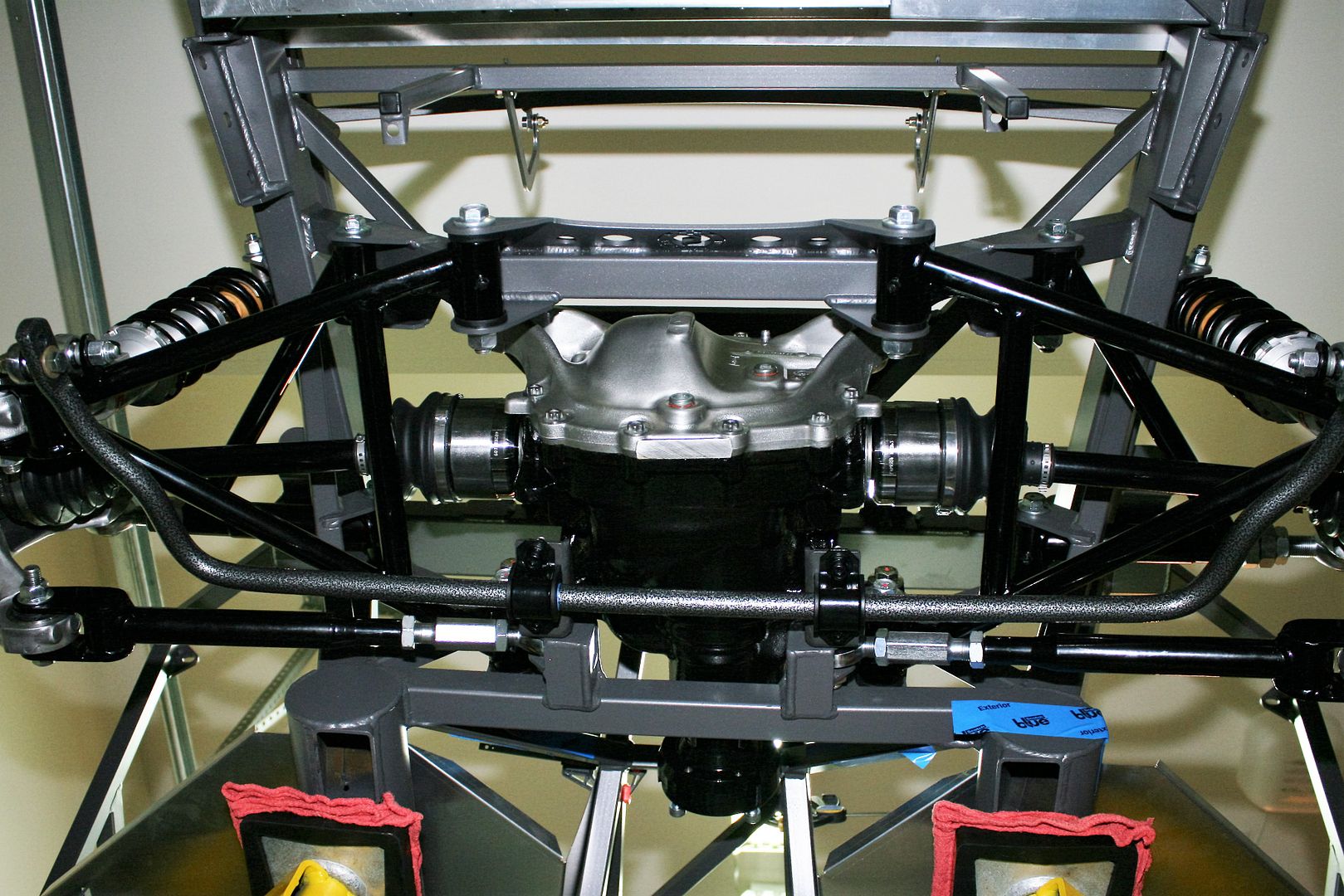
    I’ve had a couple questions about the two lower cross-axis joints in the Mustang knuckles. They are not replaced, but used as is. The main joint (the rear one) fully pivots and turns. Like a Heim joint. It appears to be a heavy duty and well made piece. The toe arm joint (the front one) is some type of elastomer, and just flexes once bolted down. It’s pretty large and flexible. The instructions clearly state to torque the bolt down with the suspension in the level position. Makes sense. You can feel some resistance from the joint when moving the suspension up and down. The top joint is the bolted in large rod end showing in the pictures, which comes with the kit. Hope this all makes sense. I’m learning about this stuff for the first time.

    So here are some pics. Really not much else to say. I think it turned out great and looks really good. Looks an awful lot like what we saw at Factory Five during the open house. But makes a difference when it’s really your car. Everything turns nice and smooth. Just need to remember to add fluid at some point.

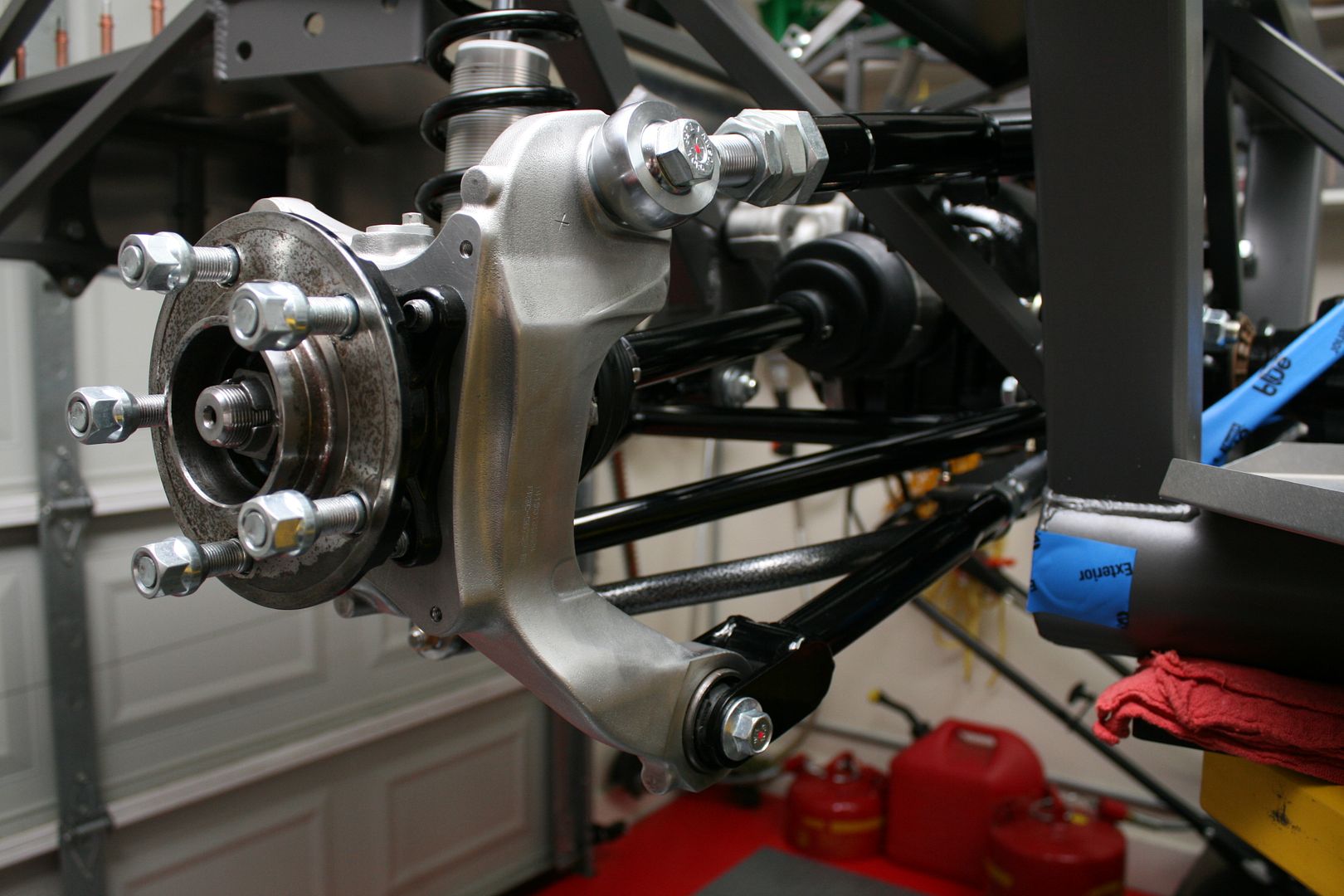
    Passenger side from rear. Note in all the pictures the suspension is drooping, as it would with the chassis on the lift. The final position is the upper control arm and CV axles level, and the lower control arm pointed slightly down. Note also I haven’t done anything with alignment yet.


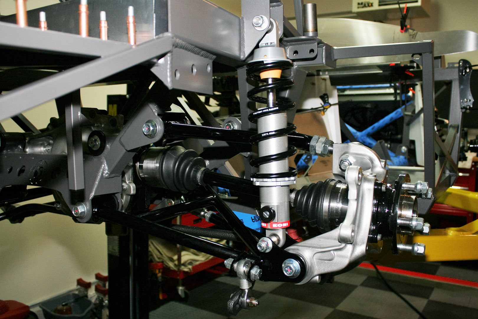
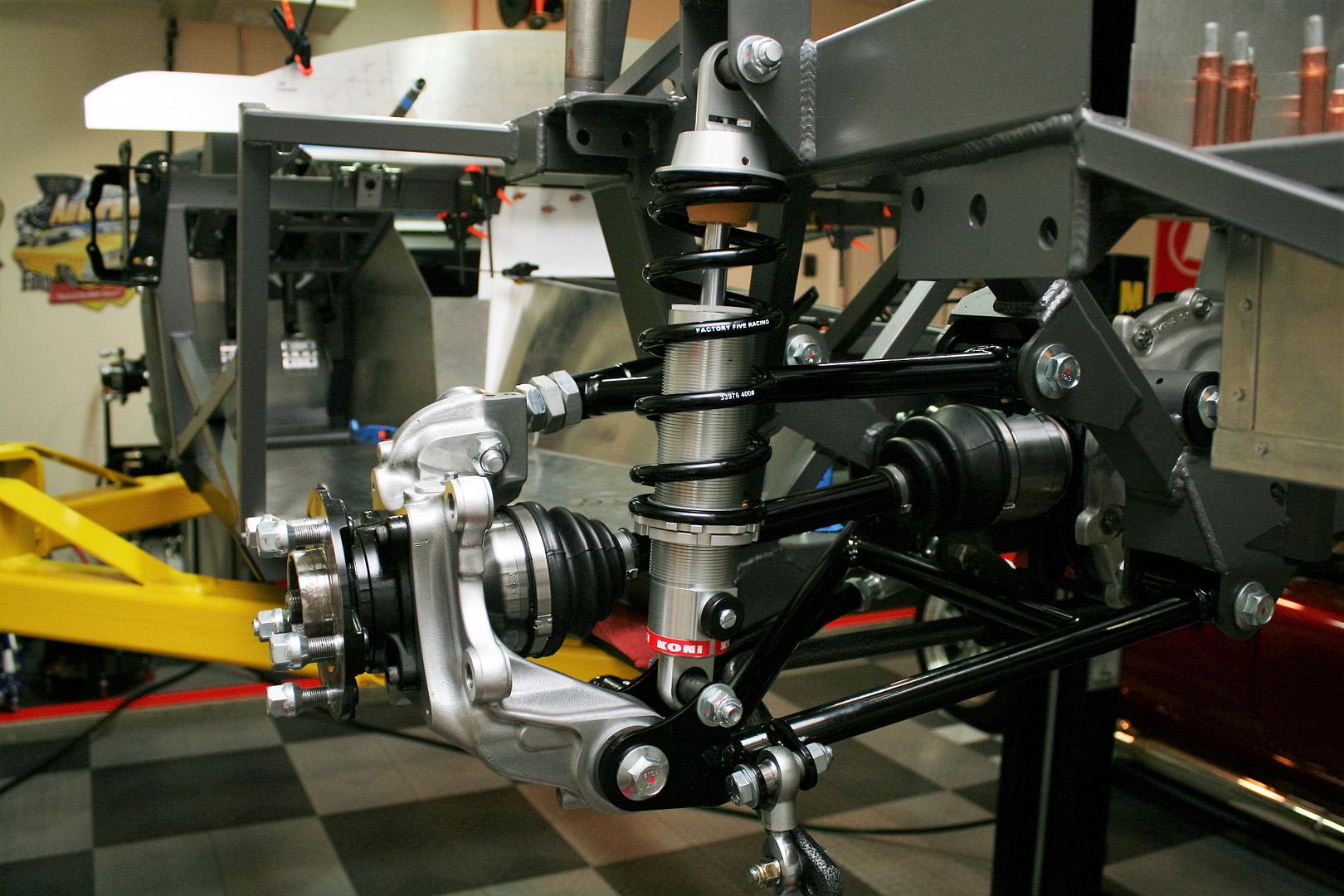
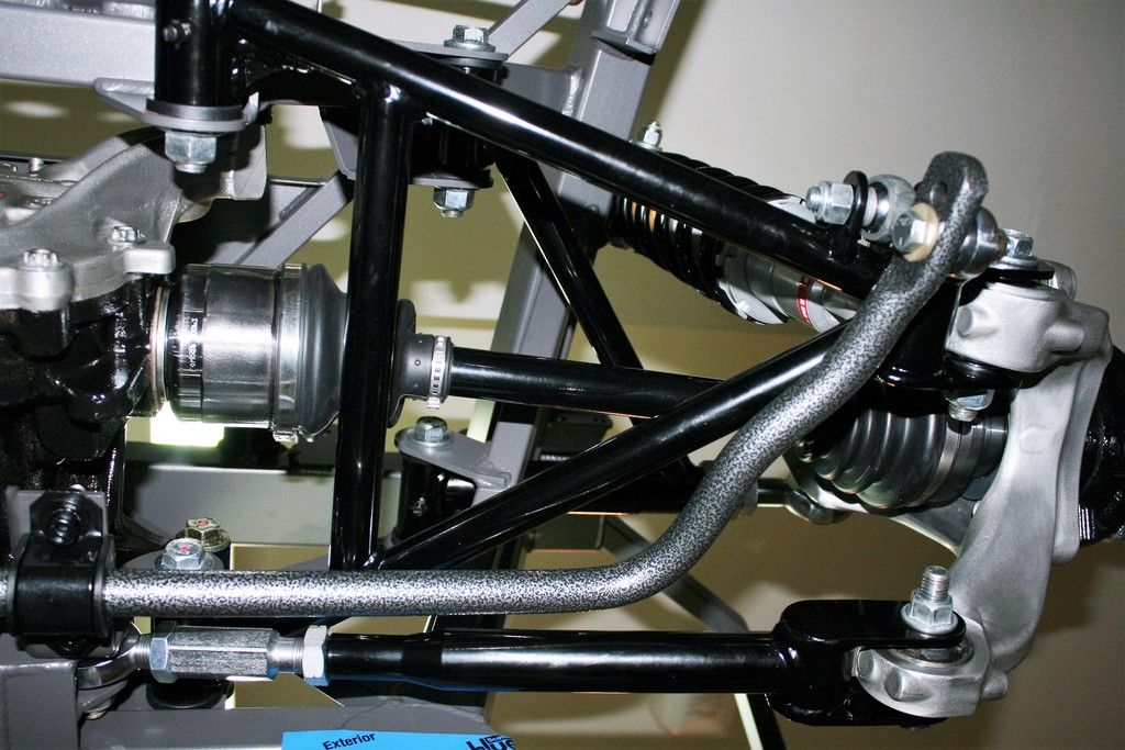
    Passenger side from front. Note the large adjuster for camber. The toe adjustment is a little harder to see on the inner part of the lowest arm. Note none of these have to be disassembled for adjustment. Just loosen the jam nuts and adjust in place.


    Driver’s side from rear. Looks kind of like the passenger side.


    Entire IRS from back.
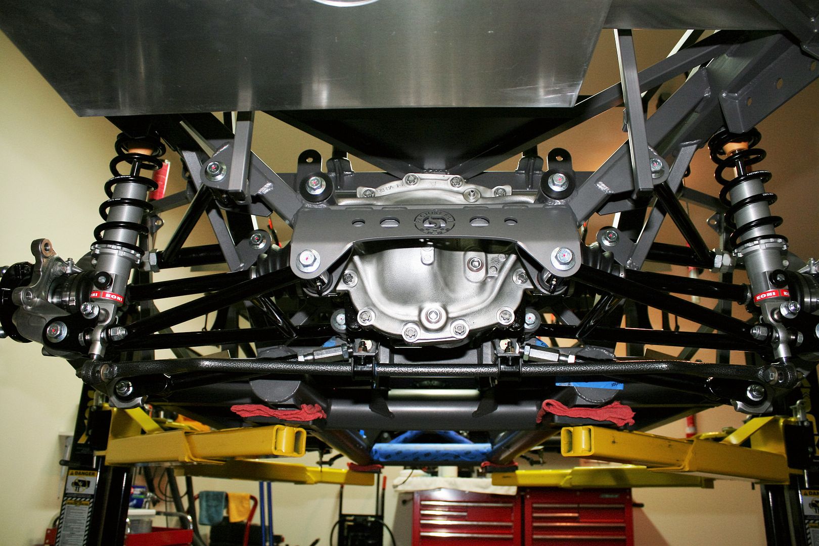


    Looking up.


    Closer look at the passenger side from the bottom. Can see the toe arm adjustment a little better here.


    Well that’s it. Pretty cool. Tomorrow I’m going to be finalizing my Coyote engine order. That’s next up.
    Hey Edward is there special tabs on the frame for the rear sway bar?
    Mk4 # 8834 delivered 03/20/16 2015 IRS wildwood brake upgrade, 18"x9" front 18"X11" rear halibrand wheels, 390 FE, tko600

  38. #277
    Senior Member edwardb's Avatar
    Join Date
    Feb 2011
    Location
    Lake Orion, Michigan
    Posts
    10,567
    Post Thanks / Like
    Quote Originally Posted by Hottrodder427 View Post
    Hey Edward is there special tabs on the frame for the rear sway bar?
    I assume you mean the inner attachment points for the rear sway bar. There are two brackets that should have come with your sway bar setup. They are held to the chassis by the bolts for the toe arm and the lower control arm. The kit comes with a longer bolt for one. The other is long enough as supplied. I don't remember which is which, but it's pretty obvious when you assemble it. Adding the bracket during IRS assembly is mentioned in the IRS instructions and sway bar instructions. Here is a picture I took showing the added bracket. I had it powder coated. It comes in plain steel.

    Last edited by edwardb; 05-20-2016 at 06:28 PM.
    Build 1: Mk3 Roadster #5125. Sold 11/08/2014. Build 2: Mk4 Roadster #7750. Sold 04/10/2017. Build Thread
    Build 3: Mk4 Roadster 20th Anniversary #8674. Sold 09/07/2020. Build Thread and Video. Build 4: Gen 3 Type 65 Coupe #59. Gen 3 Coyote. Legal 03/04/2020. Build Thread and Video
    Build 5: 35 Hot Rod Truck #138. LS3 and 4L65E auto. Rcvd 01/05/2021. Legal 04/20/2023. Build Thread. Sold 11/9/2023.

  39. #278
    Senior Member
    Join Date
    May 2013
    Location
    Slidell la
    Posts
    311
    Post Thanks / Like
    Thanks a bunch
    Mk4 # 8834 delivered 03/20/16 2015 IRS wildwood brake upgrade, 18"x9" front 18"X11" rear halibrand wheels, 390 FE, tko600

  40. #279
    Senior Member edwardb's Avatar
    Join Date
    Feb 2011
    Location
    Lake Orion, Michigan
    Posts
    10,567
    Post Thanks / Like

    Drivetrain Final Assembly Begins

    This isn’t going to be much of an update. But have made a little progress starting final assembly on the drivetrain, so will share. I’m waiting for the call to pick up my TKO600, then it will get really serious. Promised for any day now. In the meantime, I started hanging parts on the back of the Coyote for what I hope is the final time.

    I read through a bunch of posts, nearly all saying the stock nodular Coyote flywheel was just fine and use as is. But not being one to leave well enough alone, I still decided to go ahead and spring for the billet steel version. For my mainly street driving, no doubt massive overkill. But that’s what I did. Ford Racing now has a newer lightweight version, part number M-6375-M50, and that’s the one I used. At 20 pounds, it’s 9 pounds lighter than the standard billet flywheel and also SFI rated. The stock nodular flywheel weighs 29 pounds.

    First order of business was to remove the stock flywheel, which I would have had to do anyway to install the Quicktime blockplate. In this picture you can see the Coyote crank position sensor and trigger wheel. Found some discussion about this maybe needing to be relearned once the engine is back together. But I didn’t disturb it and the wheel is keyed to the flywheel bolts so it can only go one way. By most accounts, it should be fine with no further actions. Notice also in this picture I moved the homemade engine lift bracket from the rear header location to the back of the head. Early in the build thread I showed the lift brackets I made since Ford no longer provides them or even has them available. For whatever reason, I didn't notice there were lift locations on the back of the PS head. This location is much better and also avoids the PS footbox during installation.


    New flywheel in place. I had installed the clutch dowels before mounting here. The usual overnight in the freezer and they drove in pretty easily. I used new flywheel bolts, which is recommended. They aren’t expensive.


    I chose to use the Ford Racing M-7560-T46 clutch, which is actually a Centerforce dual friction part. It’s no secret. The box, parts, and instructions say Centerforce all over them. By all accounts it’s a good clutch and is the one recommended in the FF Coyote installation instructions. This is the side of the clutch disk that goes against the flywheel. Kind of different.


    Here the clutch disk is on the flywheel using the alignment tool. Not included with this clutch kit, BTW, but I had one on hand.


    Clutch assembly complete. New bolts here as well. First time I've seen those counterbalances that Centerforce uses. Also kind of different.


    Installed the TOB on the clutch arm and had the bell housing on and off a few times getting the clutch fork pivot ball adjusted to the right height. Once satisfied, locked it down with blue Loctite and a good grunt and put everything together. I’m using Mike Forte’s hydraulic clutch setup, so had previously bolted the pivot block on the end of the clutch arm. Also shot a little Eastwood chassis black on the exposed part of the arm and pivot. Just don’t like bare metal.


    I can’t bolt it on until I have the transmission, but did a sanity check on the slave cylinder mounting block and pushrod. Looks like it’s going to line up perfectly. Like on my last build, I’m going to hook up the hydraulic line, bleed the system, and confirm proper operation of the hydraulic clutch before the engine is installed. Everything else looks like it’s lining up properly. Now just need to hang the transmission there.
    Last edited by edwardb; 03-09-2017 at 03:14 PM.
    Build 1: Mk3 Roadster #5125. Sold 11/08/2014. Build 2: Mk4 Roadster #7750. Sold 04/10/2017. Build Thread
    Build 3: Mk4 Roadster 20th Anniversary #8674. Sold 09/07/2020. Build Thread and Video. Build 4: Gen 3 Type 65 Coupe #59. Gen 3 Coyote. Legal 03/04/2020. Build Thread and Video
    Build 5: 35 Hot Rod Truck #138. LS3 and 4L65E auto. Rcvd 01/05/2021. Legal 04/20/2023. Build Thread. Sold 11/9/2023.

  41. #280
    Senior Member edwardb's Avatar
    Join Date
    Feb 2011
    Location
    Lake Orion, Michigan
    Posts
    10,567
    Post Thanks / Like

    Drivetrain Final Assembly Begins (continued)

    Another detail I completed was the Tangent running lights that go into the front oil cooler opening. I’ve used those on each of my builds and like the look and they’re somewhat functional. They do add some lighting for nighttime driving. But mainly I think they make the car easier to see by others. The version they’re selling now is a study in laser cutting. I was going to get the base and brackets for the center SS grille powder coated. But decided just to clean them up and spray with the satin Eastwood Chassis Black I’ve been using for a bunch of other stuff. Then assembled, hooked up the wires, and it’s ready to go into the body.


    The light fixtures each have a small 194 style miniature bulb and a high intensity fog lamp style bulb that light separately. I added a 2-way (high-off-low) switch on the dash next to the headlight switch, a relay tied to the headlight switch so they only work when the running lights or headlights are on, a relay for the fog lamps (too much for the switch) and then wiring out to the front of the car.

    I’m working on the roll bars and will get those all fitted and ready to go. I’m installing the Tangent hidden mounts for those. But will stop as soon as the phone rings for the transmission.
    Last edited by edwardb; 05-24-2016 at 07:16 PM.
    Build 1: Mk3 Roadster #5125. Sold 11/08/2014. Build 2: Mk4 Roadster #7750. Sold 04/10/2017. Build Thread
    Build 3: Mk4 Roadster 20th Anniversary #8674. Sold 09/07/2020. Build Thread and Video. Build 4: Gen 3 Type 65 Coupe #59. Gen 3 Coyote. Legal 03/04/2020. Build Thread and Video
    Build 5: 35 Hot Rod Truck #138. LS3 and 4L65E auto. Rcvd 01/05/2021. Legal 04/20/2023. Build Thread. Sold 11/9/2023.

Page 7 of 20 FirstFirst ... 5678917 ... LastLast

Posting Permissions

  • You may not post new threads
  • You may not post replies
  • You may not post attachments
  • You may not edit your posts
  •  

Breeze

Visit our community sponsor