-

Yes, I love Technology


Originally Posted by
turbomacncheese

... I'm interested in the things you've done with the mill (vs how you got the mill to CNC). You know, first find a reason, THEN build the tool!
Thanks.
Since it went CNC:
holes in plate for dashboard
steering wheel adapter parts for NRG
mount plate for cruise control with NRG
parts for intake induction valve & airbox backfire blowoff parts
3 different "flanges" for intake: airbox, engine ends, bellmouths inside airbox
adapter/converter plate for throttle body to airbox
Prior to that I used the mill (have had it about 5 years) every so often for something for my telescope, gun parts, model RC car/planes and lately the 818 - milling pipes to fit for strut building, etc. Adding CNC got me two things - more accuracy when parts are made that must fit together, and especially more complex operations and especially X10 where you need to make several of the same thing.
-
Yes, I love Technology
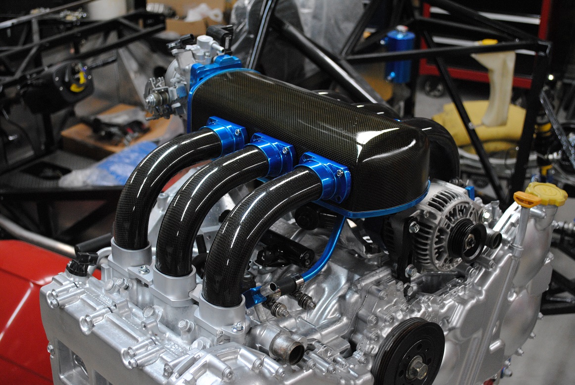
Thanks all so far re the carbon fiber. There is just something about carbon fiber parts that gets a lot of us interested. High tech, lightweight. This manifold if I didn't say it - 7# vs the 35# Subaru. That alone is just cool.
Last edited by aquillen; 10-09-2018 at 05:04 PM.
-
Post Thanks / Like - 0 Thanks, 1 Likes
-
[QUOTE=aquillen;342682]
holes in plate for dashboard
steering wheel adapter parts for NRG
mount plate for cruise control with NRG
parts for intake induction valve & airbox backfire blowoff parts
3 different "flanges" for intake: airbox, engine ends, bellmouths inside airbox
adapter/converter plate for throttle body to airbox
See, NOW you got me thinking!! Thanks!
Originally Posted by
aquillen
Thanks all so far re the carbon fiber. There is just something about carbon fiber parts that gets a lot of us interested. High tech, lightweight. This manifold if I didn't say it - 7# vs the 35# Subaru. That alone is just cool.
You deserve every last bit of that praise, too!
-
Nice work!
For the transmission being too close to the frame, you can cut off much of the back end if you weld a plug into the hole you can see from the back side.
-
Senior Member

Originally Posted by
aquillen
No!! You did not! Unbelievable! And the finish quality looks like that of Koenigsegg's!
You built yourself a home-made autoclave, impossible but you made it! I don't know what else to say, I'm frozen in time!
What's next? Copying the ENTIRE car frame in carbon fiber?
Frank
818 chassis #181 powered by a '93 VW VR6 Turbo GT3582R
Go-karted Aug 5, 2016 - Then May 19+21, 2017
Tracked May 27/July 26, 2017
Build time before being driveable on Sep 27, 2019: over 6000h
Build Completed Winter 2021
-
Yes, I love Technology
Originally Posted by
Mechie3
Nice work!
For the transmission being too close to the frame, you can cut off much of the back end if you weld a plug into the hole you can see from the back side.
I have been contemplating that, in my back pocket if needed. Thanks!
-
Yes, I love Technology
Originally Posted by
Frank818
No!! You did not! Unbelievable! And the finish quality looks like that of Koenigsegg's!
You built yourself a home-made autoclave, impossible but you made it! I don't know what else to say, I'm frozen in time!
What's next? Copying the ENTIRE car frame in carbon fiber?
I wish it was an autoclave, just vacuum bagging so far. Would be a cool thing to have though. Frame in CF? Hmmmm... 
-
Senior Member

Color me impressed with your work - and I've done a bunch of design requiring CNC and carbon hand layup and machine layup (CTLM, ATLM, etc) for my job every day
Nice job!
Gen 3 Type 65 Coupe builder
-
Member

I really enjoyed your build up.
Thanks
Eric
-
Yes, I love Technology
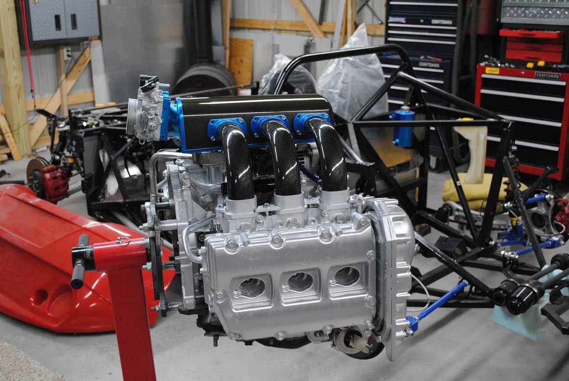
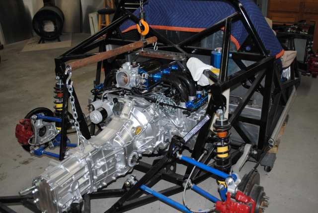
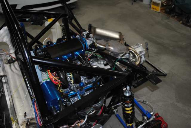
First start - its alive, ahahhhhahh
Got the ECM/TCM parts wired to the engine enough to try starting. Happy to say it fired right up. Don't have any other wiring yet, so fuses and jumper wires were used today.
I rather expected a vacuum leak with all the component parts involved with my homebrew CF intake, but it settled into a proper idle immediately. If there was a leak I'd think it would idle way high.
https://res.cloudinary.com/aq007/vid...art_sqt1ms.mp4
Took about a week to wire the engine components to the ECM/TCM. I never had a harness, so just connectors with pigtails. Next step will be to bundle and tape my wire groups to clean up what I've wired so far.
Started making cylinder/piston parts for hydraulic shifter I'm going to try next.
Last edited by aquillen; 01-08-2019 at 11:18 PM.
-
Post Thanks / Like - 0 Thanks, 1 Likes
-
Way to go!! Always exciting when they start!!
-
Senior Member

-
Senior Member

Great day, congratulations!
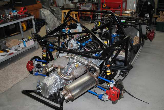
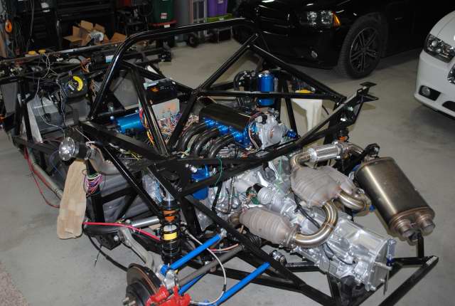
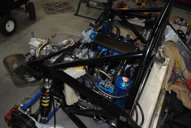
Let's see some pics of the engine/intake now that it's in the chassis.
-
Yes, I love Technology
Originally Posted by
DSR-3
Great day, congratulations!
Let's see some pics of the engine/intake now that it's in the chassis.
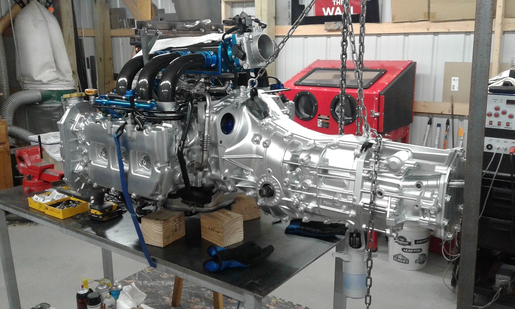
Workin' on it now. Got some more intake info to post 1st.
-
Yes, I love Technology
Intake airbox construction
Some of the steps building the airbox. The carbon fiber tubes were covered above.
The initial tube and airbox shapes were roughed in using blue construction foam, carved with a knife and hot nichrome wire knife. The airbox in foam was easy to damage, so I made a better one from balsa wood (still flimsy but easier to sand, shape, paint).
First a profile pattern for supporting ribs was drawn, in Microsoft paint no less... Then this was resized and saved several times, each one "lower" in profile but same width at the bottom. The profile changes created the slight taper where the "front" of the box is lower than the back (throttle body goes at the back).
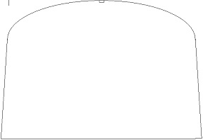
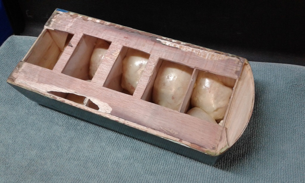
Paper templates were printed, then balsa formers were cut from each template. Like building a model airplane airframe, planks of balsa were glued. The whole box was filled with some "Great Stuff" to help keep the wood from changing shape with humidy, etc.:
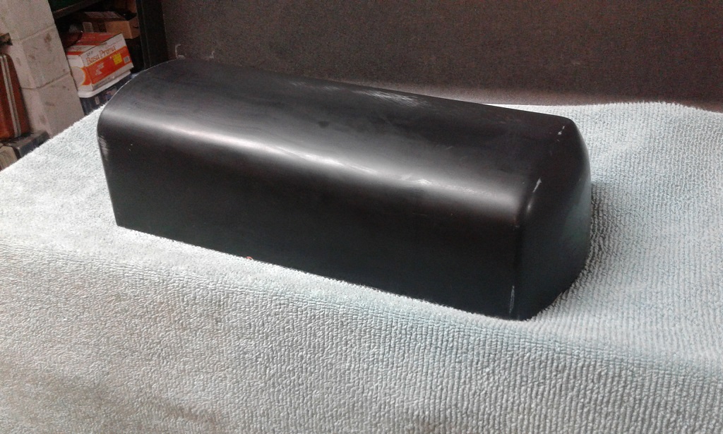
The outer form is sanded, sealed, painted. It was nicer than this pic but has been bumped around since used:
A fiberglass mold is prepared from the plug.
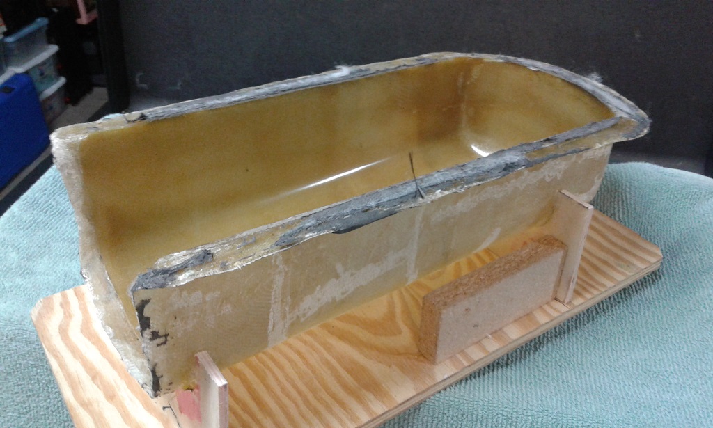
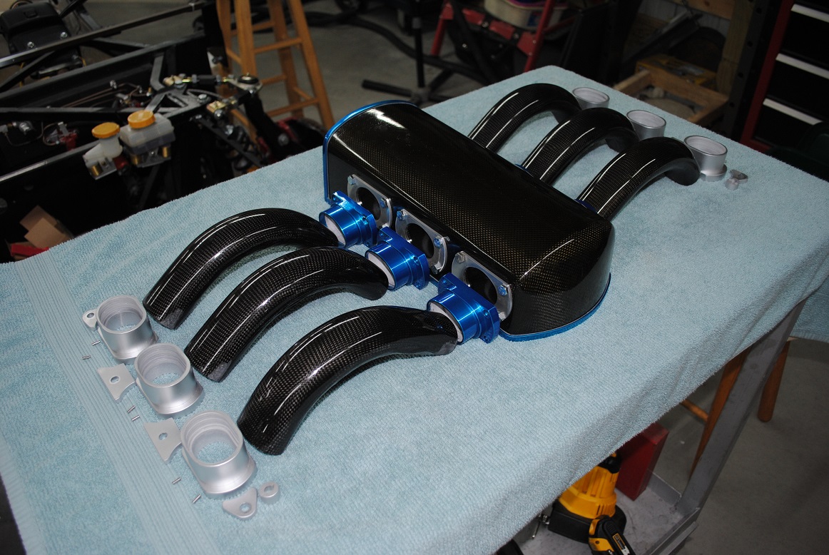
No pictures of building the actual shell in the mold, but it was 10 layers of CF cloth. Vacuum bagging was used as well. The resin I used for the tubes, vane parts (detailed below), and this box is Fibre Glast 3000 which gets oven treatment once the parts are removed from their molds. After oven curing, the 3000 epoxy carbon fiber parts are good for 309 degrees F, per Fibre Glast.
I selected this resin because it can be oven cured AFTER removing from the supporting mold. Some epoxies must be kept in the mold during curing or they change shapes.
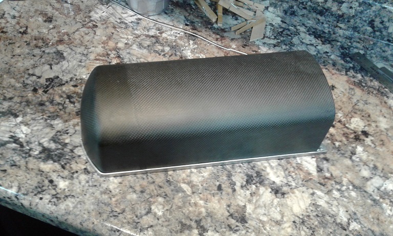
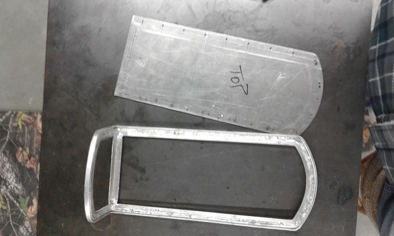
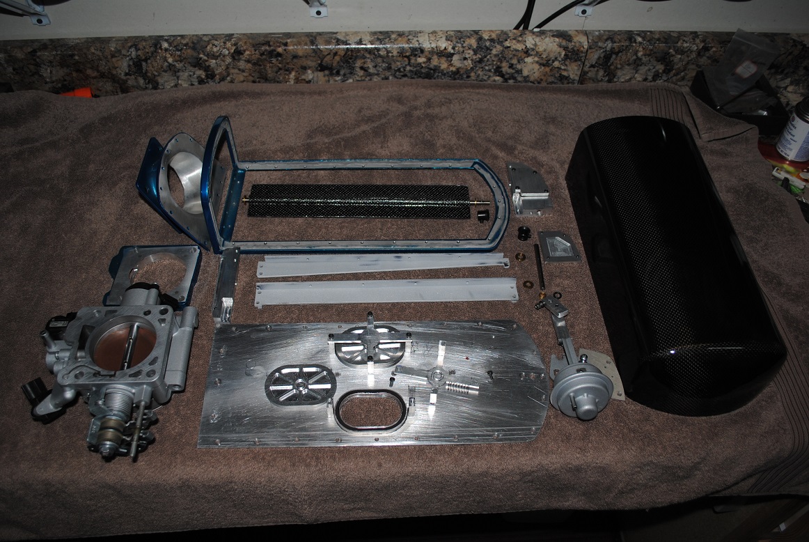
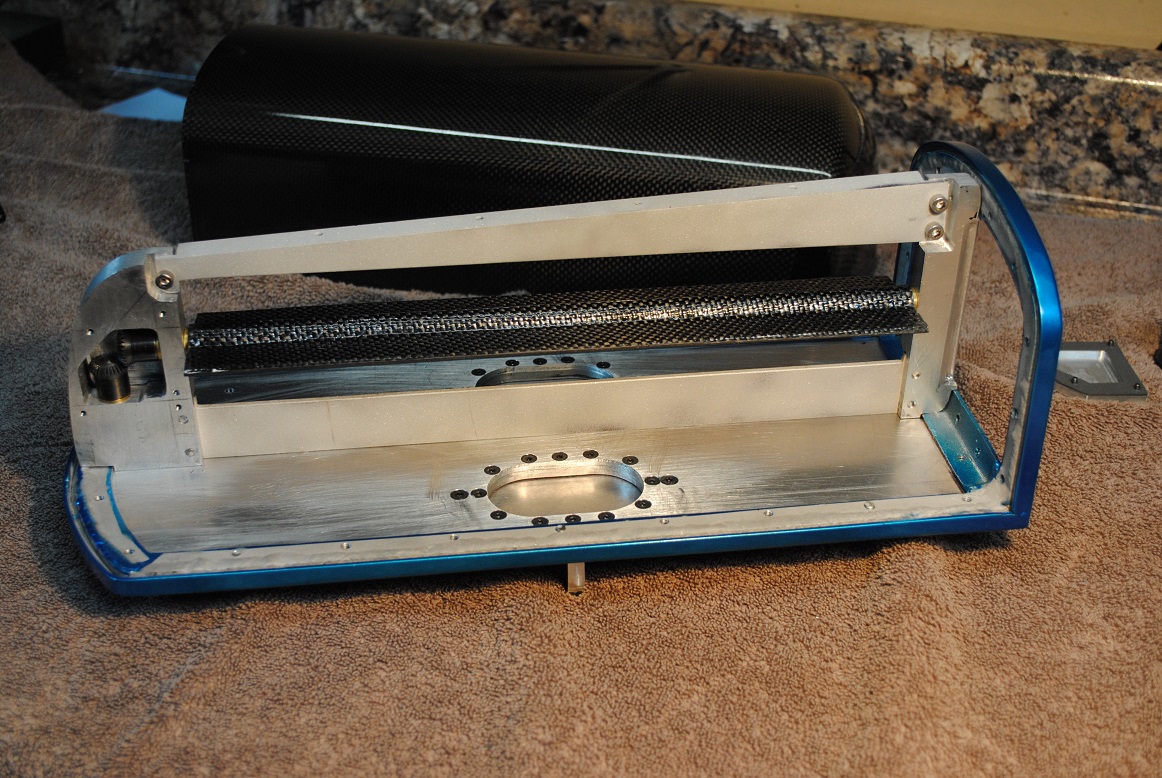
End result, sitting on the aluminum frame bottom (next):
Last edited by aquillen; 01-08-2019 at 08:38 PM.
-
Yes, I love Technology
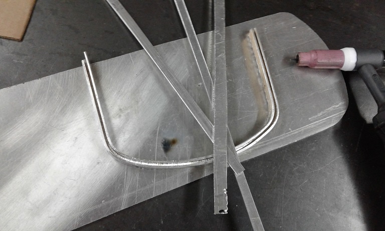
The aluminum frame is made from 0.1" sheet, cut in strips and tig welded. I did hand form a U-shaped frame the first time around but after hours, it was nice, then needed an adjustment that damaged it. Decided to make the U-shape frame by welding strips together - faster and stronger. Either way, get it right or start from scratch each time. 'Lot of time here.
The U shape creates a cup that the bottom lip of the airbox CF can be bonded down into. Vacuum/air tight, and strong to handle intake-backfire. (I know of arguments over the term intake-backfire, but I suspect you know what I mean). I can't say that I would put a boost into this airbox, but it SHOULD handle backfire's. Heck it did on the test start - notice when I jumped in the video above just as the engine caught?
The bottom plate is 1/8" aluminum. Two of the three strips are higher profile.
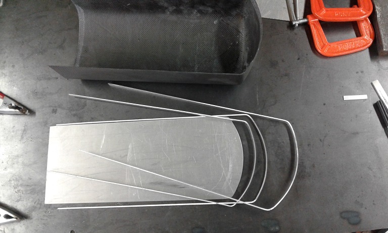
Tack welding the frame around. Later the seams were welded in longer sections. High performance epoxy eventually fills the U-channel bonding the CF box bottom into the U-channel and sealing the assembly to be air-tight. Bits of metal were inserted to help heat-sink the welding area, TIG outfit was near its lower limit and was on the verge of burn through most of the time.
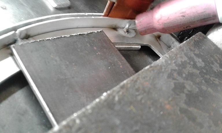
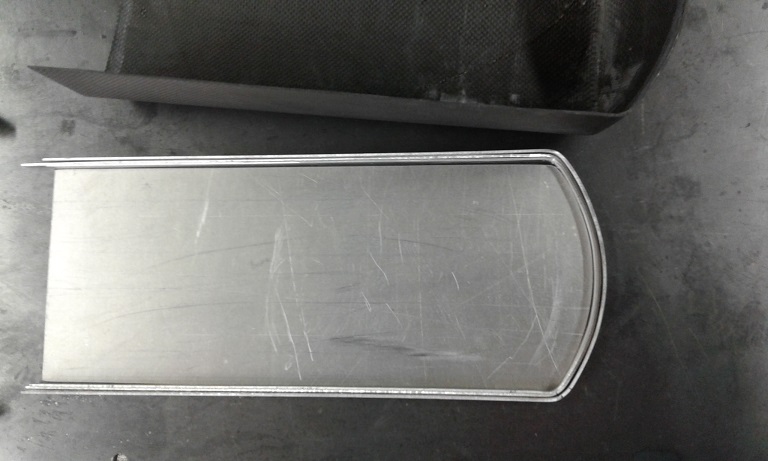
The back lip - for the throttle body mounting plate, is made the same way:
Eventually the parts are welded together. Has to be jigged and just right, the aluminum doesn't like being bent to adjust afterward (cracks).
The carbon fiber airbox is set into the frame, and bonded with this single part epoxy, which is heat cured. And costs a bundle.
3M™ Scotch-Weld™ Adhesive 2214 Hi-Temp New Formula are aluminum filled, deaerated products for use where higher strengths are required between 180°F to 350°F (82°C to 177°C).
Last edited by aquillen; 01-08-2019 at 11:22 PM.
-
Yes, I love Technology
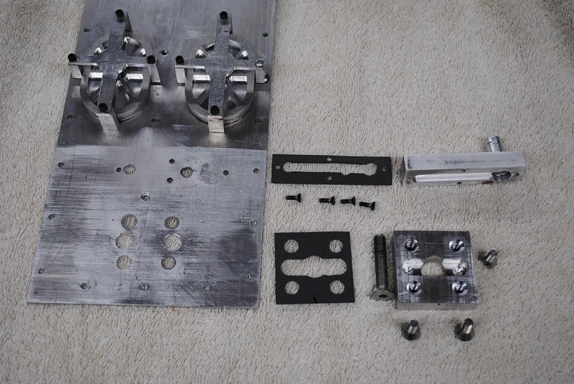
The throttle body is spaced away from the CF frame to make room for cables, etc. And to allow for a funnel shaped air inlet that enlarges as air leaves the throttle body and flows into the main airbox space.
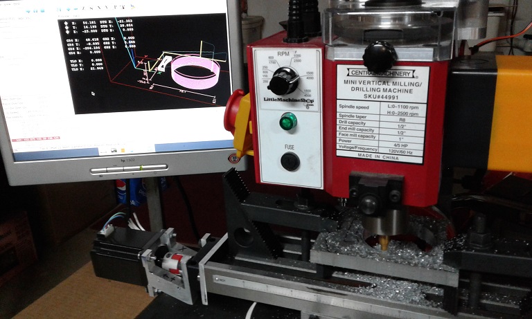
So a 1/8" aluminum plate fits directly to the back of the airbox, it is welded to a 1/10" aluminum funnel shaped part, and that is welded to a 1/2" aluminum plate fitted to the throttle body itself.
Milling the port in the 1/2" plate, to fit the outlet bore of the throttle body:
Experimenting with cardboard templates eventually defines the shape needed to make an oval-shaped funnel. The aluminum is cut and then formed by bending it in increments in a make shift jig in my press...
Jumping to some of the bottom detail. I'm trying to keep the emissions control functions. Other than adding weight, a study of these systems suggests that other than catalytic converter exhaust flow restriction, the other components should not have significant affect on horsepower. For example, stomp on the gas, the EGR system should "disengage" to not reduce power output.
OK - so coming in the bottom (under computer control) is exhaust gas from the EGR. Also arriving, again under computer control, charcoal cannister fuel vapor to purge temporary gasoline vapors stored in the cannister. These two systems typically flow into the intake under steady state highway speed driving.
Next, I have concern for an intake-backfire rendering the entire assembly back to nature. Studying other plastic intake designs, some employ various types of duck-bill or other flapper type valves to vent the intake chamber. You can find plenty of pictures, including Cadillac and other engines. Not much in calculations, but I worked out my own dimensions and pressure plans for that part. (semi-educated guessing... what else?). I have two spring held poppet valves. Each is 120% open area compared to the area of one CF intake tube. They have high temp Viton o-rings in machined grooves to seal when closed.
During my first test start, just as the engine "caught" there was a backfire. It's pretty loud, because the valve(s) opened. Well they worked at least once...
The aluminum plates have passages to ensure gas flows to either/both "sides" of the airbox regardless of the induction valve (detailed next) is open or closed.
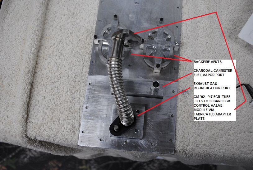
I worked out the flex tubing for the EGR by visiting my local LKQ-Upick yard, and snooped around all kinds of engine compartments to see what I might adapt and use. They didn't even charge for the 5 tubes I came out with....
-
Post Thanks / Like - 0 Thanks, 1 Likes
-
Yes, I love Technology
Induction valve....
The 01-04 H6-3.0 motors emply a "variable induction valve". It was about as simple of this sort of valve used, and was an early adopter of the scheme. A great number of engines now employ variable induction schemes because they take advantage of "ram air" type airflow. Loosely stated, resonant waves of airflow "slam" back and forth between the engine's cylinder intake valve backside faces and the airbox interior, flowing up and down through the intake tubes. With the right geometry, more air can be moved down the tubes and into the cylinders. But as RPM's change, the air shock wave travel speed being rather constant (~speed of sound~) the length of the tubes ideally should be changed to keep getting the best air-flow-cylinder-fill performance.
Whew. Better stated by others, but close enough for my discussion here.
The Volkswagon - Vanagon guys and gals, and some Subi fans have been transplanting the H6 into their favorite underpowered ride. Some have described that when they have removed the functionality of the variable intake control, the engine has a rich fuel "hiccup" at the point where the valve would normally be switched by the engine computer (~4300 RPM if I remember right - not looking it up again). So I wanted to try to keep the function, and hopefully also get the slight performance improvement that the variable intake valve gives.
In the bottom of the OEM intake manifold are two "belly's" or chambers, with three intake tubes to one chamber each. A brass plate (the valve) on a pivot axis can be opened or closed to spit or combine the two chambers. The computer opens or closes this valve to change the overall volume of the two chambers, and mostly, to let the intake shockwaves travel across from the left and right intake halves (or not). = more power at certain RPM ranges.
So what the heck, I made something along the same lines. Probably this time more of an uneducated guess, but hey, I'm trying at least.
Biggest concern really is the shock waves (and there are a lot of them at X RPM, non stop mayhem in there) could tear up the parts I put inside. Then the parts go where they will REALLY mess things up - cylinders.
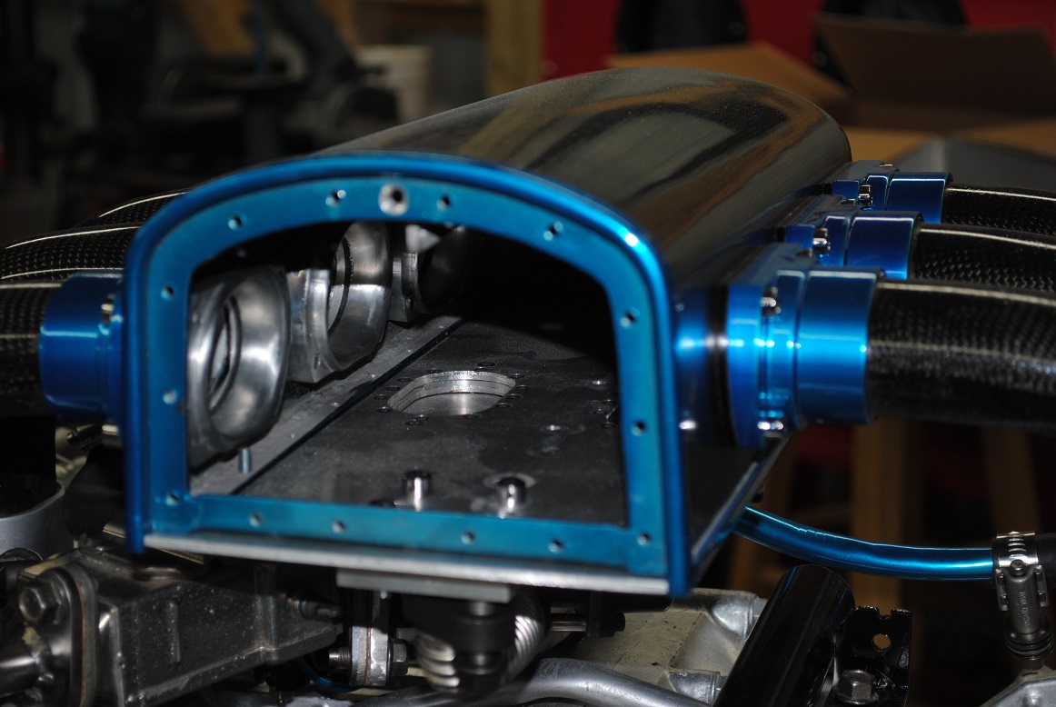
Carbon fiber to the rescue? First, an end view of what is inside the box.
Vane closed:
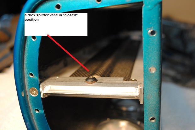
Vane open:
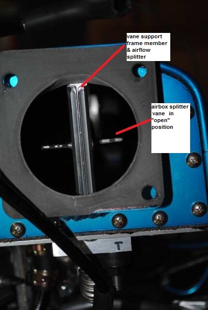
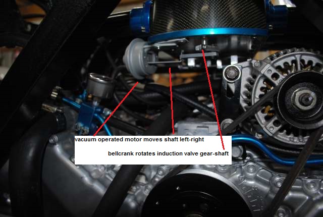
The vane is operated by an oil-filled gearbox at the front, inside, with operater shaft extending out the bottom of the airbox. The original vacuum motor, computer controlled, operates my version of the "variable intake valve".
Last edited by aquillen; 01-08-2019 at 11:29 PM.
-
Post Thanks / Like - 0 Thanks, 1 Likes
-
Yes, I love Technology
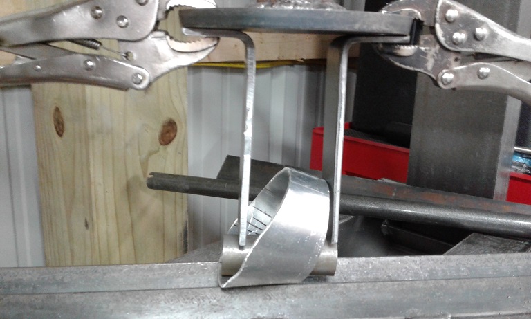
Fabricating the induction valve.
The frame parts, valve plate itself, has to be stiff to avoid flex. Of course that provokes a resonant frequency problem as well, and resonance is what brings down airplane wings, span bridges, and big windmills, etc.. The best hope then is just make it as stiff as possible and roll the dice. I just don't have the finite analysis stuff, etc., to play like a big boy.
Forging ahead then,
The vane started with 1/2" hard aluminum rod, with 1/8" slots milled on opposite sides, to support bonding perforated aluminum plates. Perforations allowed the epoxy resin to mate throughout the assembly to bond the CF better. The curve induced in the CF overlay increases the CF bend resistance immensely. (Immensely = a very scientific amount...)
Milling the slots -

The perf aluminum sub-frames, bonded with good'old JB Weld. All oven baked to drive out contaminants, then sand blasted and cleaned in prep for carbon fiber overlay.

This 10 layer carbon fiber vane was laid together and then vacuum infused to get as much strength as possible given home-brew.
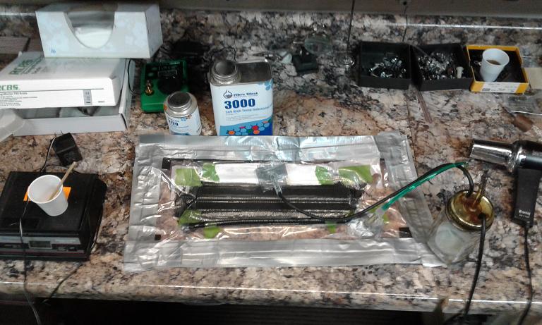
These pictures I posted before, but for continuity:
Last edited by aquillen; 01-08-2019 at 10:16 PM.
-
01-08-2019, 10:40 PM
#100
Yes, I love Technology
-
Post Thanks / Like - 0 Thanks, 1 Likes
-
01-08-2019, 10:59 PM
#101
Yes, I love Technology
-
Post Thanks / Like - 1 Thanks, 0 Likes
-
01-08-2019, 11:10 PM
#102
Yes, I love Technology
-
Post Thanks / Like - 0 Thanks, 1 Likes
-
01-08-2019, 11:10 PM
#103
-
Post Thanks / Like - 1 Thanks, 2 Likes
-
01-16-2019, 08:12 AM
#104
Senior Member
Woa, there's nothing "ok" in your build. Every single part, as small or big as it is is "awesomely off the chart"!
Frank
818 chassis #181 powered by a '93 VW VR6 Turbo GT3582R
Go-karted Aug 5, 2016 - Then May 19+21, 2017
Tracked May 27/July 26, 2017
Build time before being driveable on Sep 27, 2019: over 6000h
Build Completed Winter 2021
-
01-24-2019, 10:33 AM
#105
I truly am blown away by the craftmanship. Wow....
-
05-06-2019, 08:48 PM
#106
Yes, I love Technology
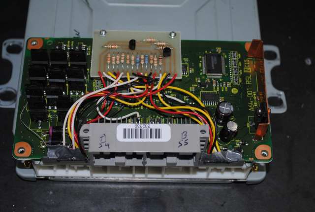
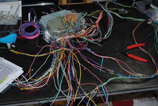
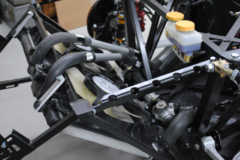
Back to the engine harness
Since I didn't use a donor, my parts came from here and there, LKQ yards, friends, eBay. The Subaru engine harness bugged me, a jumble of tape, plastic guides, corrugated sleeving, tape, tape and more tape. It seemed to me the carbon fiber intake deserved better below it, not this stuff:
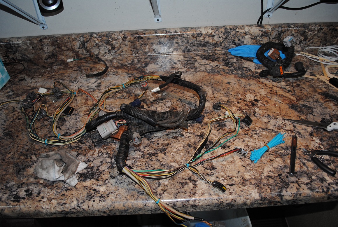
My "first draft" reworked harness is the one that I started the engine on back in January (vid above).
BUT it was made with more splices than I could count, and after changing lengths here and there mid-build, the splice count doubled from there. Also I used a bunch of new wire that ended up with insulation way thicker than Subaru uses. My final harness was thick and bulky. Especially right in the neighborhood of the alternator when installed...
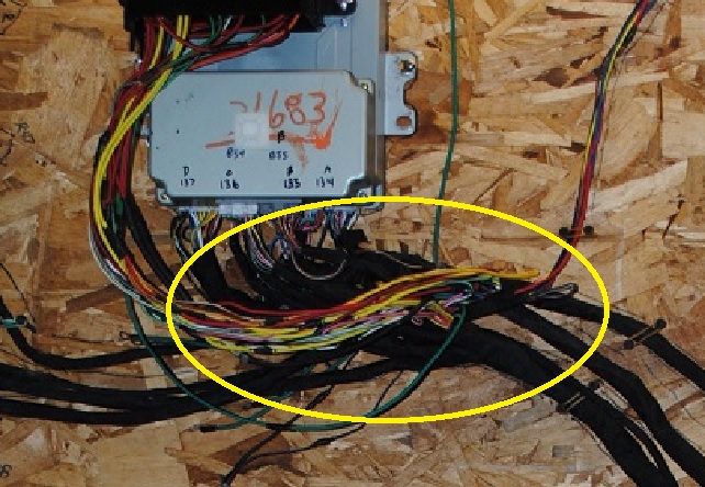
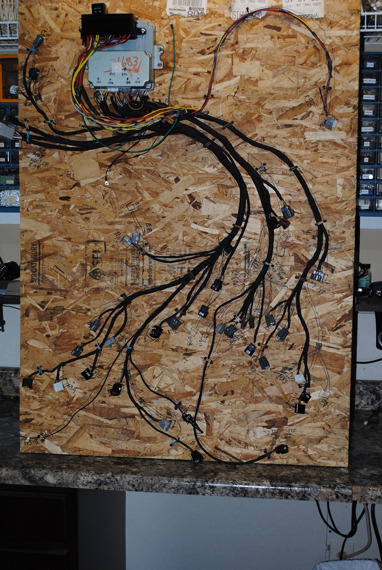
So, it ended up be a "proof of concept" harness. But now, with good lengths to all the connectors on the engine and such, I used it to setup a layout board with connector lengths marked up on the board. I snagged an under-dash harness super cheap on eBay and it had the ECU, TCU connectors I needed plus a mass of wires in the color codes matching everthing I needed to build a visually better looking harness, even if electrically it was just a re-run:
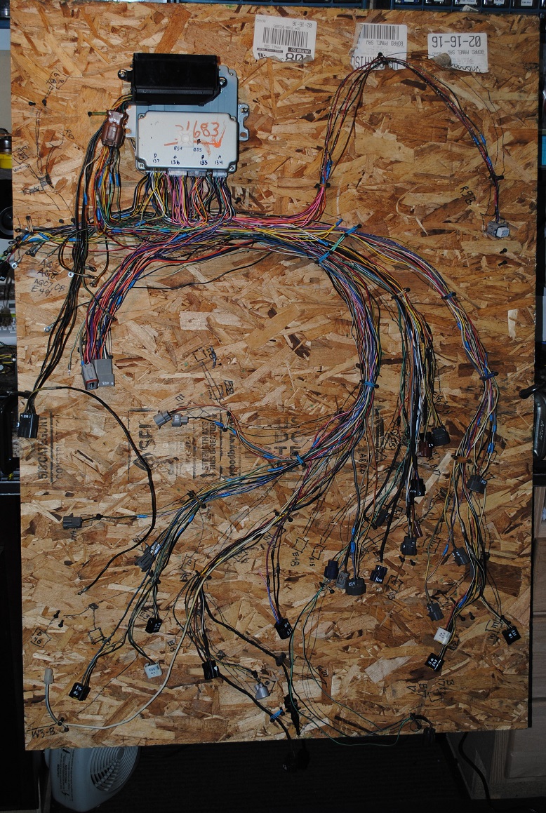
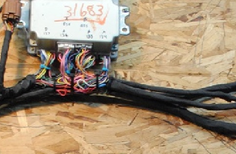
I've run the engine a number of times on this one and now wonder how I made such a mess the first time around 
-
Post Thanks / Like - 0 Thanks, 1 Likes
-
05-06-2019, 09:13 PM
#107
Yes, I love Technology
Of mice and men and cooling, or "How many acorns fit in an 818's coolant piping"
A recap of some plumbing, (H6 3.0 engine) -
Return to engine:
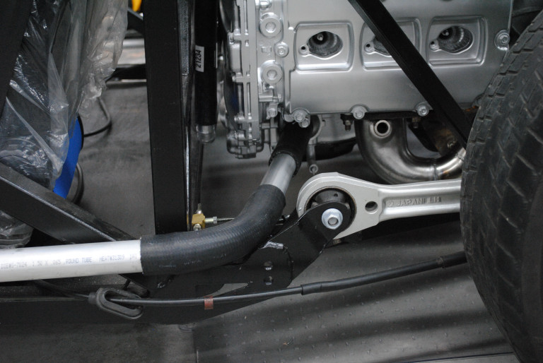
Hot to radiator:
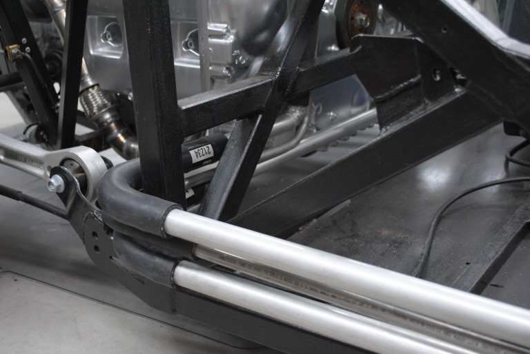
Sitting in 8 acres of mostly oak trees, last fall was a bumper crop of acorns. My brother lives in the city but likes to feed his local squirrels. He was coming for a visit so I blew an hour collecting a couple tubs for him. Put them in my garage like a dumbo. I also occasionally trap a mouse out there. Connect the dots?
About the time he got here the acorns had sprouted worms and got thrown out. But that's just the beginning. I have the feeling they would have fermented and exploded given a few more days...
I started finding little collections of acorns in strange places. A cardboard box inside a cabinet my band saw sits on. Behind bottles of oil and lube in another cabinet. Behind the tig welder that has sat for several weeks dormant.
This is back in October mind you. Late December I'm getting to the engine wiring, installing the engine and looking forward to first start fun. The acorns fiasco has been long forgotten, or so I thought.
With the engine out of the chassis in the fall, the coolant hoses closest to the engine, on each side were removed but all the piping from the back of the chassis to the front was in place. After putting the engine back in the frame, I was moving one of the pipes while putting the first hose back on and an acorn rolled out. OMG.
Did I say OMG? Not exactly, more like O-S and other sailer's words I thought I'd left behind when I shipped out of the Navy in the mid '70's...
In the end I found both hot side pipes and the return packed full and get this - acorns clear up inside the top plastic runner across the radiator. Used a flexible bore scope to make sure it was all cleaned out. Had to flush and rag-drag the insides of the pipes. Also water flushed the whole piping system. Plan to dump a complete load of coolant before this goes on the road, although for now I have it filled for testing.
I set more traps. My brother is on his own. There were acorns in the muffler and exhaust pipes piled over in the corner. I hate mice. One got run over when I was backing out of the garage a few weeks later. What a mess, but I grinned.
Last edited by aquillen; 05-06-2019 at 09:16 PM.
-
Post Thanks / Like - 0 Thanks, 7 Likes
-
05-06-2019, 10:26 PM
#108
Yes, I love Technology
Jumping out of my perfectly good airplane - clamshell hood
Got bit by another "do it different" bug. Work in progress, might take a while to finish this so I'll come back to it later. Given issues others have had with body part alignment, I'm taking a chance not having the whole coupe and such installed, but I'll just cut and 'glass as needed when the time comes.
So far -
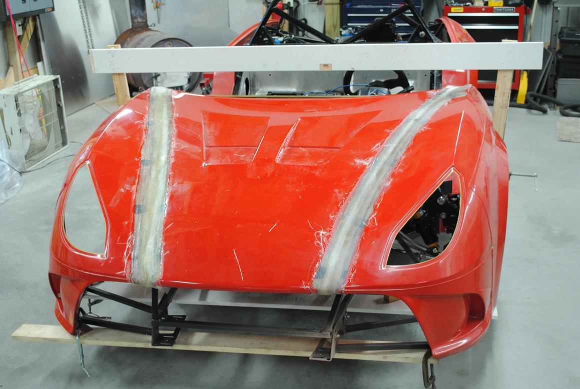
First, assembled the hood and front sides, guided by the rear fender's - running board's - front corners to the back-bottoms of the front left and right fenders. Made up some clamps here and there and marked boards and stuff so it could be removed, installed repeatedly in the same locations each time. Goal is to define where the hood to fenders should be. This is because next the fenders and hoods mating lips will be ground away and all obvious means of alignment would be lost.
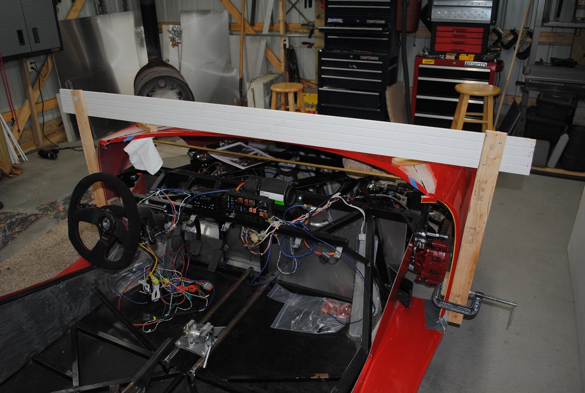
This is a little further along picture wise but shows what I was getting ready to do for alignment with no guiding hood-fender interface lips. Boards at the bottom front used to get the bottom back in place after pulling the fenders off for the cut/grind step coming up.
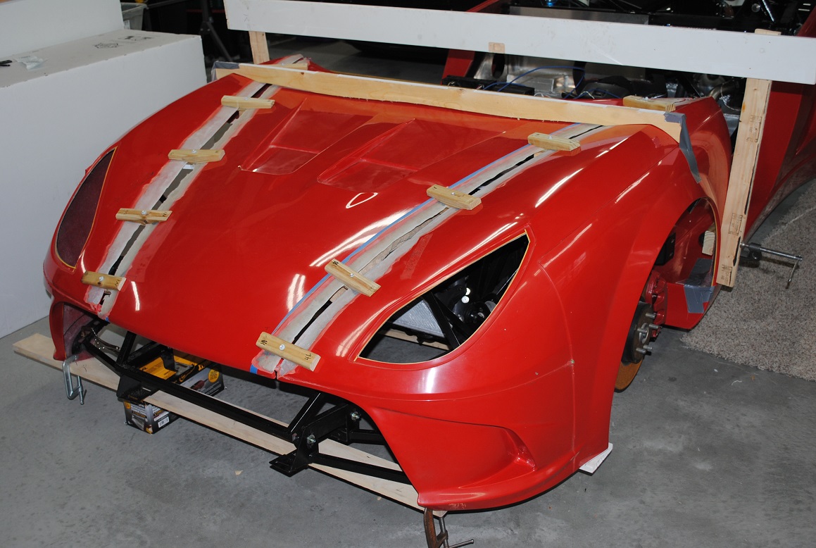
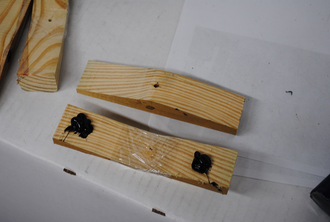
Some scrap 2x2 wood blocks were profiled to match the curve of the hood/fender mating lines. Band-sawing these blocks roughly in half created pairs of top-bottom "alignment" blocks that will hold the hood to fender positions later when the "lips" have been cut off the fiberglass edges of each piece.
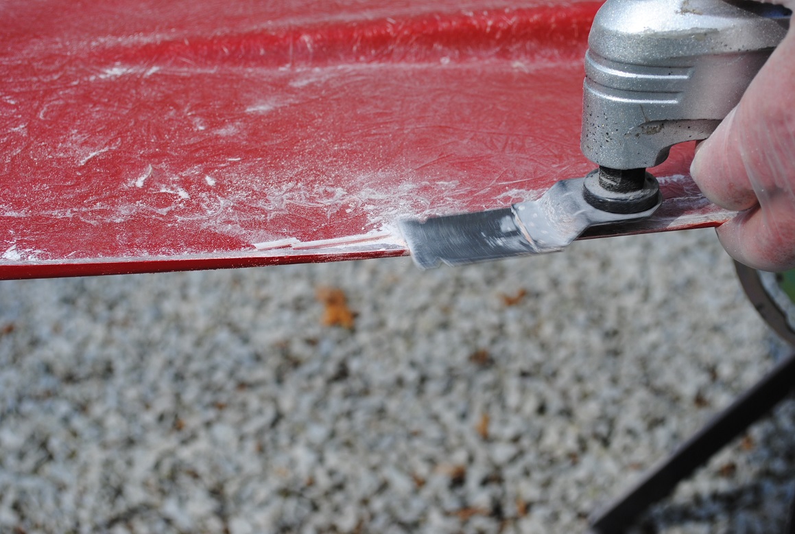
The sides and hood come off the chassis and the mating edges are changed from lips to flat sheet. Repairing/mating fiberglass edges are feathered by the standard rule of a 12:1 ratio where the feather-taper is 12 times the thickness. In this case for the 1/8" thick glass/gel coat I ground about 1.5 inches in from the edge to down to paper thin at what used to be the mating "lips":
A "multi-tool" type vibrating saw is easy to control and works well for this sort straight cutting (on fiberglass and carbon fiber composite too). I'm rough cutting the lip of one of the pieces here:
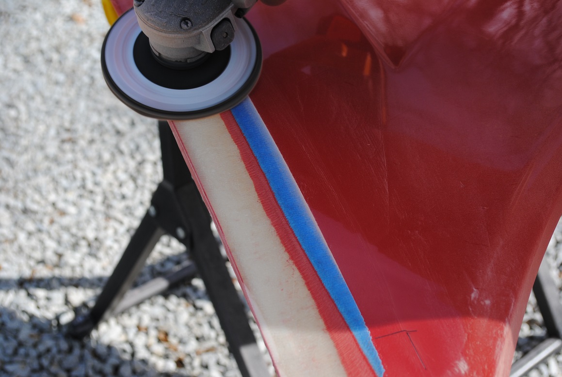
Next we grind. Always a mess. Tape line guides the 1.5 inch from edge. This had to wait for good weather here in NW Indiana so I could go outside.
Back together again, the wood blocks, bottom side only are pasted with some body panel adhesive, and screws are run through from the top to clamp the block pairs. Once the bottoms are bonded, the top blocks can be removed so glass can be laid into the seams. All the block pairs are in place in the picture posted above. Later, a chisel easily separates the bottom side block from the body adhesive and excess left can be ground away. I may add some glass to the bottom side later, depending on how things look/feel.
Several strips of glass are laid in with vinyl ester resin, each strip is wider than so the highest strip spans nearly to the un-ground surface about 1.5 inches in from the edge. Since I didn't setup underlay to fully support the new glass, it sagged down the open seam and will need some filler work. Should have setup a support from underneath to prevent this. Live and learn. Kitty-hair to the rescue...
More on the work to follow, including the hinge structure I have in mind.
Last edited by aquillen; 05-06-2019 at 10:31 PM.
-
Post Thanks / Like - 0 Thanks, 5 Likes
-
05-07-2019, 06:43 AM
#109
Senior Member

As always, amazing work! Can't wait to the see the hinge mechanism.
-
05-07-2019, 05:23 PM
#110
Amazing amount of work and quality. Checking in daily for hopefully more updates! keep at it
-
05-07-2019, 05:44 PM
#111
I've been considering a clamshell as well, eager to see how this turns out. Thanks for blazing a trail.
-
05-16-2019, 05:34 AM
#112
Senior Member
The finished product of this build will be worth almost as much as a 250 GTO...
Frank
818 chassis #181 powered by a '93 VW VR6 Turbo GT3582R
Go-karted Aug 5, 2016 - Then May 19+21, 2017
Tracked May 27/July 26, 2017
Build time before being driveable on Sep 27, 2019: over 6000h
Build Completed Winter 2021
-
05-16-2019, 07:21 AM
#113
I cannot wait to see how this piece of the vehicle compares to your gauges, airbag, etc. Great work!!
-
05-16-2019, 09:48 AM
#114
Yes, I love Technology
Originally Posted by
Frank818
The finished product of this build will be worth almost as much as a 250 GTO...
$15-20K is a bit short of $35-45M but appreciate the thought. You've got a great build yourself!
-
05-16-2019, 09:50 AM
#115
Yes, I love Technology
Originally Posted by
redbudrr
I cannot wait to see how this piece of the vehicle compares to your gauges, airbag, etc. Great work!!
I did consider the airbag but decided not to push my luck. Engineering on that, even just transplanting it, would require some crash testing - a bit beyond my budget/time limits.
Oh, and the only crash test dummy I have on tap is... me. So it might be a one shot test.
Currently engaged with building a shifter setup. My planned hydraulic shifter got built, complete with custom hydraulic cylinders and vent device, but I didn't like the stiffness that comes from seals tight enough to not leak under pressure (and I used top quality stuff for my cylinder design). So went back to building a more traditional sort of linkage. Pics probably next week, tested last night but need to finish some tweaks.
Last edited by aquillen; 05-16-2019 at 09:55 AM.
-
Post Thanks / Like - 0 Thanks, 1 Likes
-
05-19-2019, 07:27 PM
#116
Yes, I love Technology
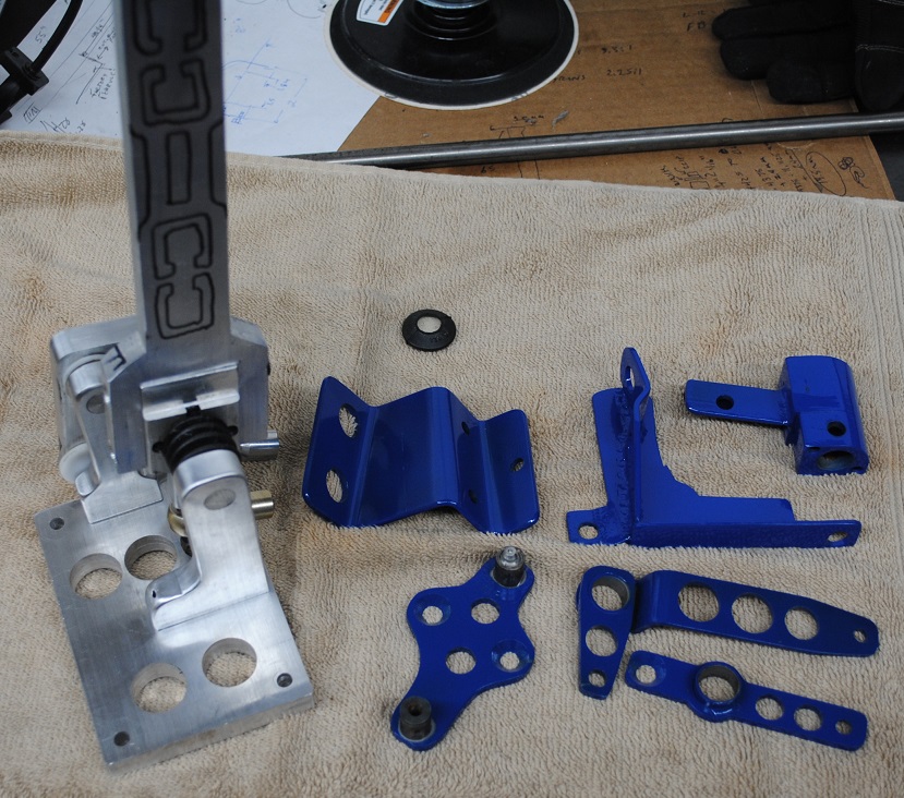
Shortening factory supplied shifter cables & some shifter parts
"yet another shifter design" -
Fiberglass went on hold while we dealt with three down trees. Then weather didn't fit to sanding outside (refuse to make a garage mess unless I have to. Way too much log pile to be split now, but some of that is done. 818 of course goes on hold when these things come up. You all know how that goes. In fact tomorrow we start on a bathroom remodel... Oh well ")
When the package says "do not open, no user serviceable parts inside", that's when I go to work.
So I've managed to shorten the kit's supplied cables. I also obtained a Teleflex TFXtreme Marine Control Cable and shredded that to see what is so special about something that "cannot be repaired, no serviceable parts". This same process can be used on them if you have nothing better to spend time on.
I put this shifter setup on the car a couple days back, but no pics as I was making parts and getting the linkage working. All apart now awaiting some parts from McMaster-Carr to wrap it up. But here are some bits of my take on the shifter so far.
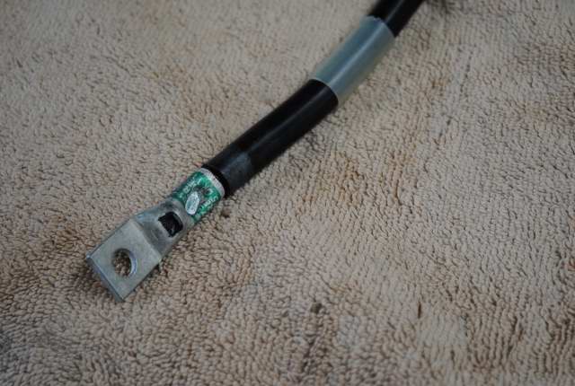
the blurry goal:
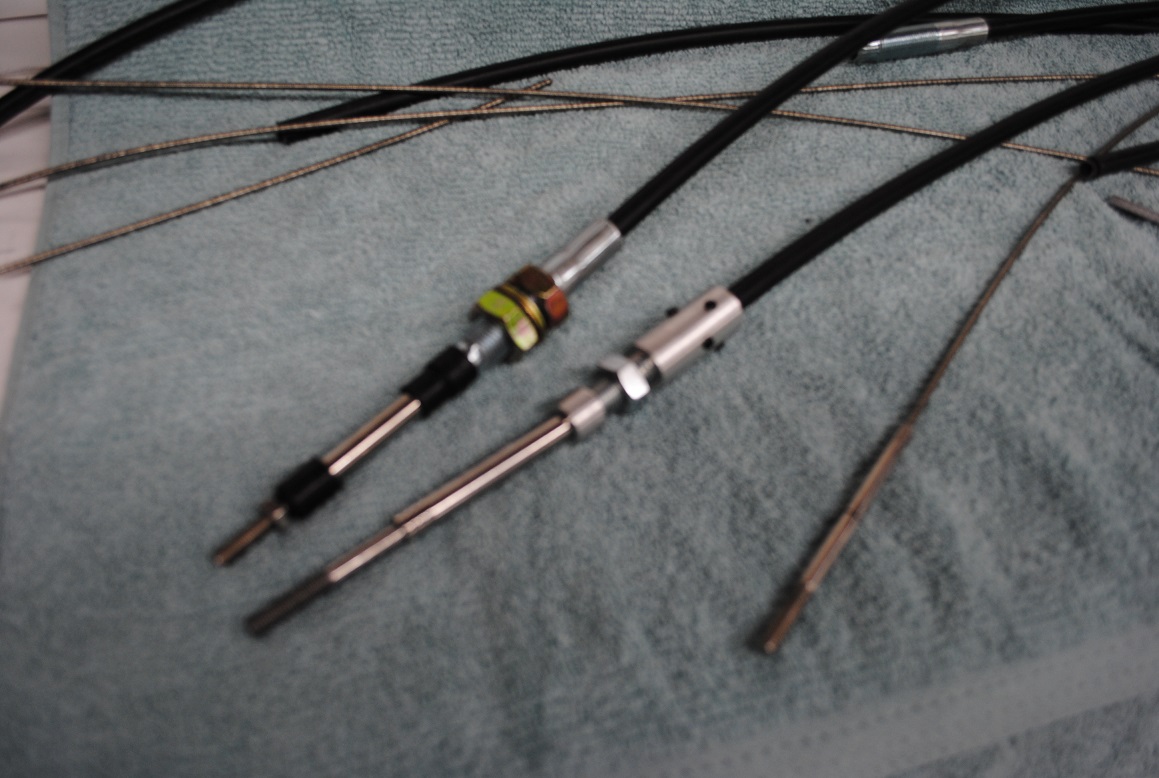
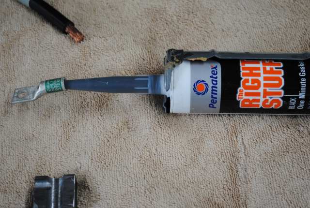
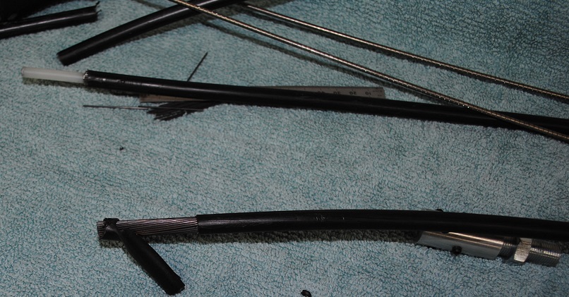
Going to cut off one end of the cable and that peice won't get used, but the flex-nozzle thingy on the end is valuable and gets used again. Cut the cable back a little bit from one end (use a metal cutting grinder - hacksaws and band saw blades will be ruined by the spring steel in the sheath and cable core). Pull off the rubber boots. Pull out the cable end and insert a screwdriver or steel rod that fits snug in the nozzle that limits cable bend angle. Rock the screwdriver in a circle, prying against the limit of angle the nozzle affords. In short order this opens the end of the cable end so the nozzle falls out.
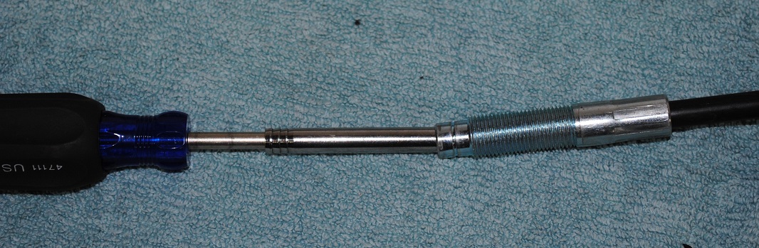
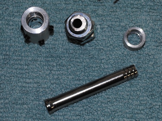
Create cable end parts: aluminum barrel about 2.5" long, threaded inside for about 1" for 1/2-20, drilled through the rest of the way for snug slide fit over the cable sheath. Six offset locations around this barrel threaded for 10-32 set screws that will clamp the cable sheath. Next a 2" length of 1/2-20 "all-thread" steel rod, with the center drilled through with 1/4" drill. A 3/4" long piece of aluminum 5/8" rod, drilled to 5/16 then drilled and tapped almost clear through for 1/2-20 rod. This makes an end cap to trap the nozzle on the end of the 2" hollow steel rod, allowing the nozzle to wobble like it did before it was molested.
Last edited by aquillen; 05-19-2019 at 09:23 PM.
-
05-19-2019, 10:12 PM
#117
Yes, I love Technology
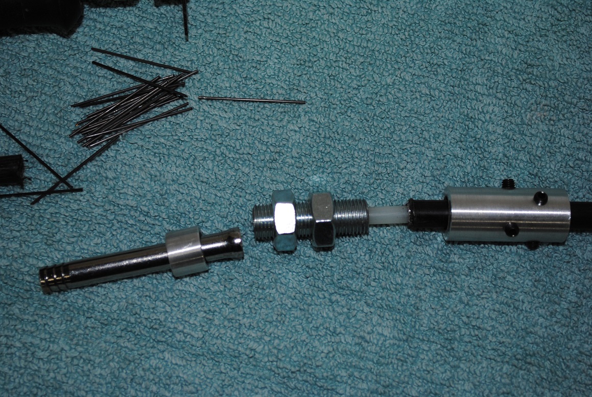
Once the final length is known, work out the length to cut the cable sheath and outer steel jacket back, accounting for how long you actually made the parts listed above. The inner cable liner was 1/4" diameter and needs to go clear to the end of the 1/2-20 rod that was drilled through with 1/4, so it supports the push-pull inner core as far out as possible. You can work out the length by examining how the original cable end was built, out to the nozzle starting point.
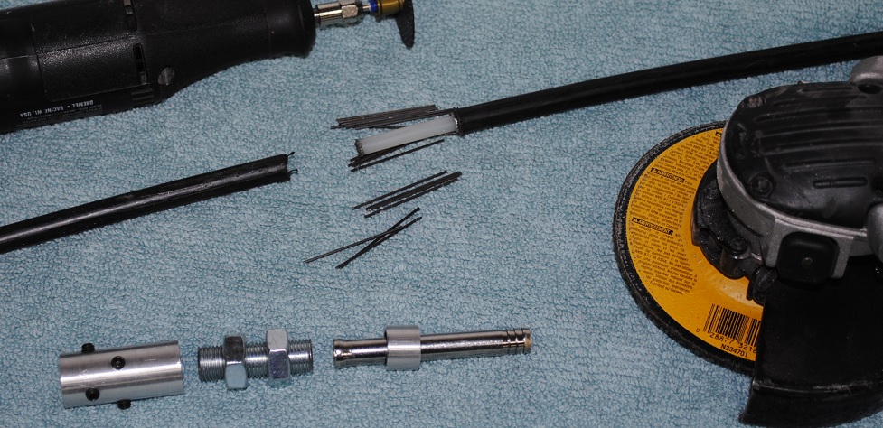
Slice around the sheath down to the cable's outer spring steel jacket (a collection of many steel rods between the inner and outer sheaths) and cut the sheath away to expose the outer steel rods.
With a moto-tool nick each steel rod about 1/3 to 1/2 through, so you do not cut into the inner liner. Bend each rod and it will break clean until you have the extended 1/4" liner beyond the rods.
The supplied cable provides about 2.5" total usable travel - actuating the rod ends back and forth. In an ideal configuration I believe you would want to use almost all this available cable travel to work the shift mechanism. Consider that the (my '98 Forester) transmission shift lever moves about 9.8mm in or out from neutral to select a gear. Total travel for it is less than an inch. But the cable can move about 2.5". I may be mistaken but I think that if a mechanical lever ratio is setup between the two motions so the cable moves nearly 2.5" to move that shift rod through it's lesser range, then "felt" slop in the cabin shift lever that is injected by the cable slop itself can be reduced by the ratio of the cable motion to transmission's shift shaft motion. Setting up a 1:1 motion ratio does not reduce that "felt" slop, etc.
I'm discussing the above for 2 reasons. First if your setup will not need 2.5" of motion in the cable, you might just cut off the end of the left over factory threaded 1/4-28 cable end rod, drill it out in the next step and re-use it. So you don't have the challenge of putting threads on a new piece of rod. The other reason will get covered later when I get pictures of my linkage which is setup to use the mechanical advantage of the longer cable motion vs shorter shift shaft motion.
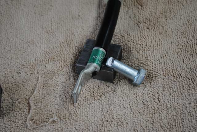
To get the full 2.5" motion in the modified unit, the end rod needs to be replaced with one you make from 1/4" steel rod, 4" long. Drill/bore into the end with 1/8" x 1/2" deep (helps to have a lathe for this). Thread the other end for 1/4-28 with a threading die. This is one spot where you need to jig up the rod in a lathe for example so that you force the threading die to stay on center. Usually running a threading die by hand onto a rod will end up running it off center unless done with some forced alignment. The threads may work but will be crooked if not forced to center while cutting the rod threads.
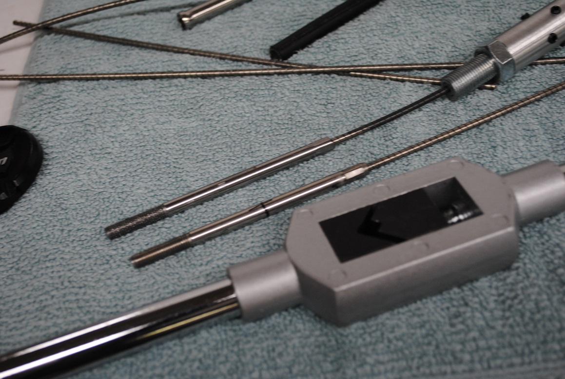
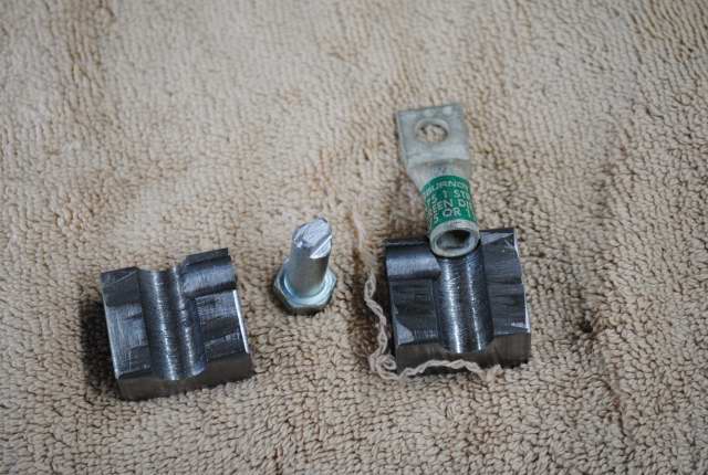
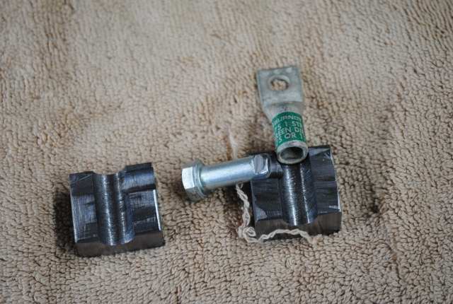
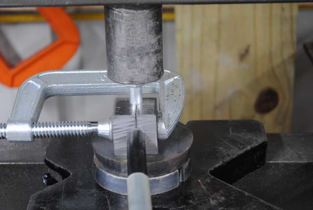
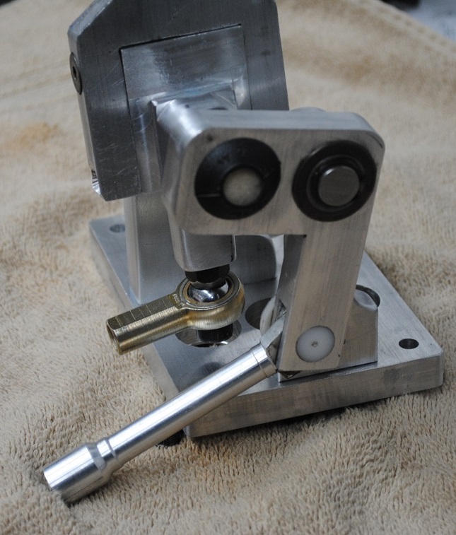
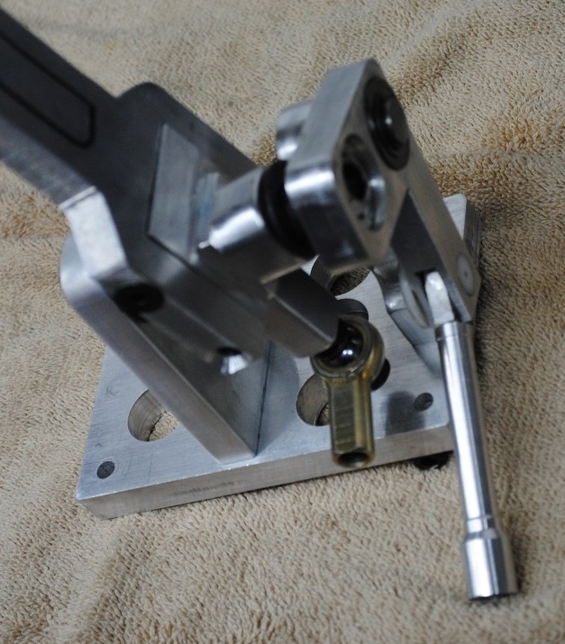
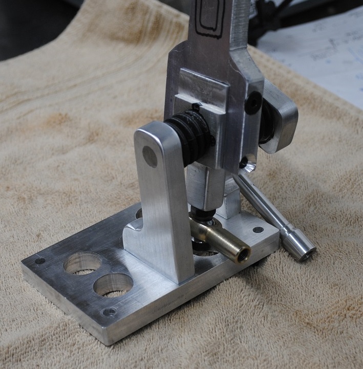
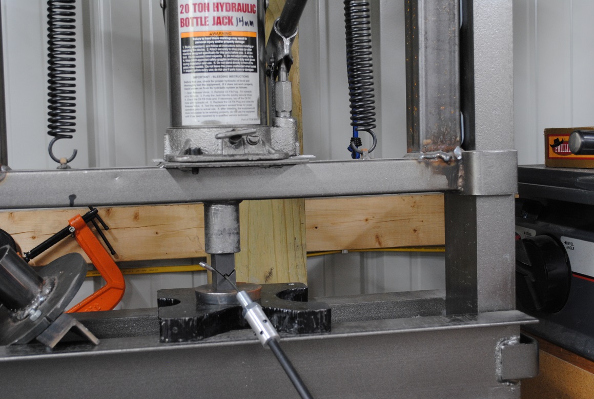
In the above picture from that tapping handle, I used the hardened steel black jaws as a crimping tool in my press. A strong vise would probably be able to crimp the 1/8" cable end inside the 1/4" steel rod but a press is a better bet. It needs to be a good hard crimp which you can probably judge against the crimp on the factory end for appearance. Granted this one is "seat of the pants". The real trick to being able to "build" your own cable end is you can access this cable end and crimp it by not having the nozzle installed yet.
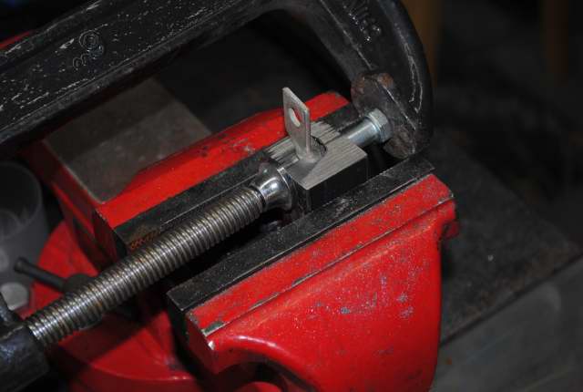
Another tap handle I had on hand was used to do the other crimp, just to see if either one would hold up to the job.
When I do something like this in my press, I wrap the whole mess in a couple big bath towels just in case the parts explode in the press.
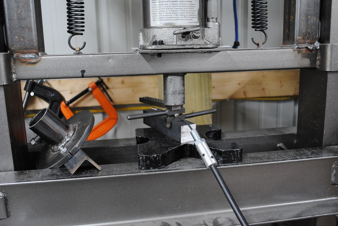
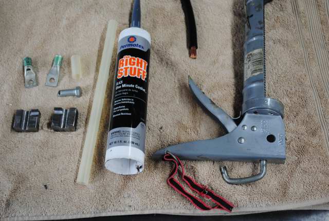
Finally the 6 set screws are driven in pretty hard into the sheath (greased up with "Right Stuff" sealant to improve water seal at the back) and the rubber boots can be worked onto the new parts.
I found this interesting - the aftermarket xTreme cable had the plastic sheath cut back and the outer steel sheath pins were exposed and physically crimped deep inside the housing barrel by part of the steel housing = crimped steel on steel. But the FFR supplied cables are crimped from the outside onto the plastic outer cable sheath, not steel on steel. For this reason I've built my cables trusting set screws driven into that (very tough) plastic sheath. I run them down until very tight but also testing that they do not cause binding of the inner cable. Another WAG on my part that remains to be proven out.
If my kingdom crumbles I'll have to buy the aftermarket cables you can spec by the inch for about 90$ each...
Last edited by aquillen; 05-20-2019 at 01:53 PM.
-
05-19-2019, 10:27 PM
#118
Yes, I love Technology
-
Post Thanks / Like - 1 Thanks, 2 Likes
-
05-20-2019, 10:42 AM
#119
Senior Member

Thanks for this, Art. Your skills are amazing; only surpassed by your courage. The next time I see "no serviceable parts inside" I'll think of you . . . then likely open and destroy it.
818S/C : Chassis #25 with 06 WRX 2.5 turbo, ABS, cruise, PS, A/C, Apple CarPlay, rear camera, power windows & locks, leather & other complexities. Sold 10/19 with 5,800 miles.
Mk3 Roadster #6228 4.6L, T45, IRS, PS, PB, ABS, Cruise, Koni's, 17" Halibrands, red w/ silver - 9K miles then sold @ Barrett-Jackson Jan 2011 (got back cash spent).
-
05-20-2019, 01:34 PM
#120
Yes, I love Technology
When I was 4 I found a music box that was made like a jukebox. Wind it up, put a coin in and it would play. Was in my Dad's closet. Took it apart and couldn't get it back together. Dad came home from work, said "I don't care what you take apart but you better be able to put it back together"... then spanked me. I've tried to follow his advice ever since.
He was a tool and die maker, took me to his work at several different jobs over the next few years and I saw and learned quickly about machinery, mechanical stuff from him.
Unfortunately, like me, he liked fast machines. When I was 12 he totaled a his new 1961 T-bird at full speed after running in a ditch and hitting a cross road embankment. His car was launched up and it clipped a telephone pole upper half off leaving maybe 10' or more of the pole still standing, the car was unrecognizable, it took him with it.
The Daily Chronicle from De Kalb, Illinois, October 16, 1962
So SLOW DOWN.
Last edited by aquillen; 05-20-2019 at 01:41 PM.
-
Post Thanks / Like - 1 Thanks, 0 Likes


 Thanks:
  Likes:


 Reply With Quote