-
11-24-2020, 07:00 PM
#321

Yes, I love Technology

-
Post Thanks / Like - 0 Thanks, 5 Likes
-
11-25-2020, 11:53 AM
#322
Senior Member

Thanks Art...good winter project...
jet
-
02-16-2021, 06:04 PM
#323
Yes, I love Technology
Can you shift gears with just your pinky ?
This is what happens when I run out of sensible projects to pursue. There was nothing wrong with my shift linkage - not a darn'd thing, But sure enough I had to fiddle with it. Last fall in warmer weather the shifter was really just fine. But I've found this car can be driven in cold weather thanks to good seals on the body/cabin working. In cold weather the transmission shift works but is pretty stiff (just the tranny's guts, not my linkages are the cause). My shift linkage is complex enough, and although i THINK I made it robust too, I was back to wondering if I could make a "power assist" and take the load off the linkages.
I have to say now, Holy Cow. It works better than I imagined. It has better feel as well. As usual, it turns out less simple than I might wish but on the other hand it isn't all that crazy as built. The coolest part is by adjusting the air pressure regulator, I can define how much help the linkage gets from the air cylinder "booster", ranging from zero to "just think about it and it shifts".... well actually you do have to touch the shift knob but that is all. I expect when I get it on the road in warmer weather I'll probably adjust the assist level to be about half what it would take to normally move the shift between gears. I didn't really expect this to be worth keeping on the car - more of an experiment than anything - but at this point I'm hoping it will survive the heat back there and work long term.
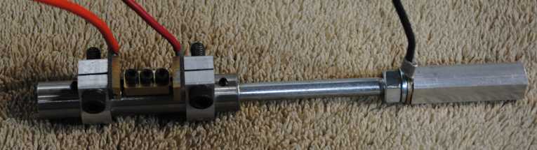
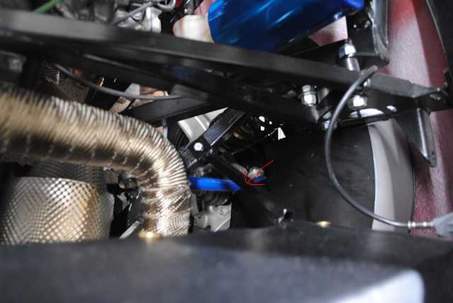
So this is an air cylinder that acts directly on the shift shaft out of the transmission to help it move in/out. The left-right-rotation motion for the shift lever is easy enough so that it got left out of the project. A small air pump and supply reserve tank supplies regulated air at about 20 to 40 PSI to the cylinder. A force sensor switch pair up in the cabin detect the front-back shift force in my linkage rods. The switches energize two solenoid operated air valves. Each valve operates one direction of the air cylinder in concert with the shift motion up front to assist moving the transmission shift shaft. Since the switches are up front and the cylinder acts directly on the transmission shaft, all the in-between parts get unloaded according to how hard the cylinder works. When the air solenoids are off the cylinder is vented at both ports and it just goes for a ride with the rest of the linkage. If the system fails, the air cylinder just follows the shifter motions with negligible drag. The only bad failure might be if a solenoid or switch stuck on and kept the cylinder acting in one direction.
Finding a small pump that could be trusted in a warm engine compartment, run very quietly, not cost much, etc, seemed to be a challenge. The force sensor switch was also something to work out - whether to just use simple electric contacts, micro-switches, magnet reed switches, strain guages, etc. The force sensor also has to be able to operate the linkage reliably even if the air assist is disabled. The air solenoids need to be quick acting to avoid a delay in feeding air to the cylinder. Unfortunately I had to modify a pump mechanically and add electronic controls and design the force sensor switch parts to get what I wanted, I couldn't find off the shelf parts. And making these parts was not a quick project by any means. Although I prefer not to have unique parts that have to be custom made, looking at this car project overall, I'm way past shedding tears over that anymore.
First I played with low cost air cylinders to see how much air pressure, cylinder force, mounting options to the transmission, etc. It worked out that I could drop the cylinder in place by pure luck with only a singe piece of steel bracket that is trapped under a spring retainer screw. This screw traps a spring that is part of the reverse lockout mechanism on this 98 Forester 5 speed. I cut a replacment screw to keep the final screw depth the same since it works against the internal spring. The cylinder rated temperature is going to be getting tested mostly by virtue of being fastened to the transmission housing through that steel bracket. This 'mission hit about 180F after an hour and half at 70MPH, give or take, last October on a 70F day. If the cylinder develops problems I will have to look into making a less heat conductive bracket (stainless steel maybe, etc.)... Sill need to fab a head shield vs. the nearby exhaust pipe. The cylinder shaft will also be a maintenance - clean it - issue as dirt not good for it (rubber boot?).
.

,
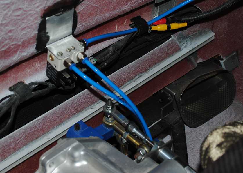
Not sure if picture perspective is accurate but may need to tweak cylinder angle to match shift rod angle...
.

.
Air solenoids located close to cylinder to minimize air transfer, line pressurization / vent delay and air consumption (reduces pump demand).
.
.
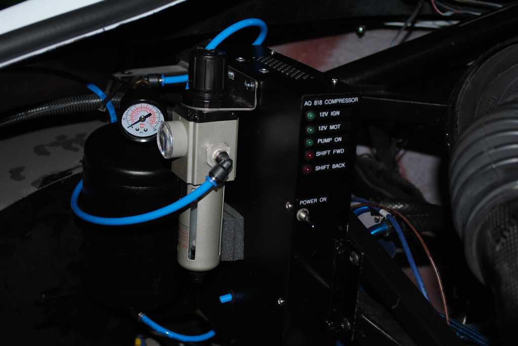
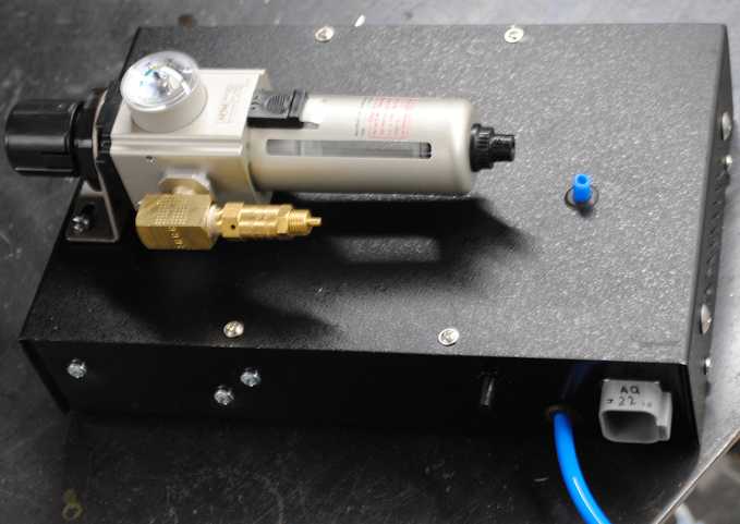
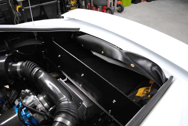
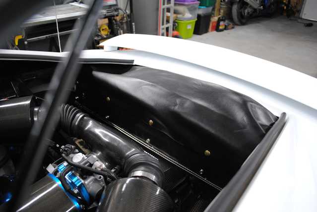
Pump module, reservoir tank, regulator mounted on left back corner of rear shock tower cross braces. Tank is an air horn, etc., component. Tank kept at 55-70 PSI. Adj reg for desired shift feel... 20-40 PSI.
.
.
Last edited by aquillen; 02-16-2021 at 06:13 PM.
-
02-16-2021, 06:05 PM
#324
Yes, I love Technology
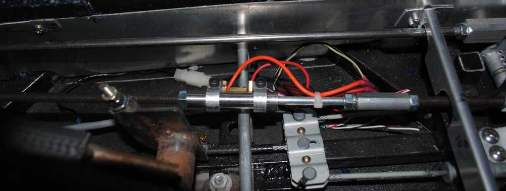
Shift shaft force sensor switch, inline under center console.
.
.
The sensor is made from 1/2" dia steel tubing. Inside are end tubes of brass, bored to a slip fit for 1/4" steel shaft that extends out one end. The other brass end is threaded for 5/16-18 rod to screw onto existing 5/16 shift rod that runs out of the back of the shifter unit. Inside the steel tube are two springs, about 30# per inch compression rate, trapped inside and working to keep the rectangular brass block centered between two adjustable clamp on contact blocks. With no force on the front-back shift lever the brass block does not contact either contact block. With about 4# of force inside the shifter sensor, a spring will compress and one related contact is made. This grounds one 12 volt solenoid back at the rear to direct air to the cylinder. The total motion allowed is ~ 1/2mm either forward or backward. If the system is not working, the contact blocks carry the shift force to the rest of the system regardless = still shifts like in the old days.
.
.
The regulator/filter has moisture capture, fine micron filter. System over-pressure protection valve opens at 90 PSI. Pump air output via the longer blue tube next to electrical connector. Tiny blue tube in middle of box is air reservoir tank moisture purge vent.
.
.
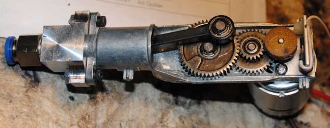
I wanted a compact, quiet and of course (hopefully reliable) compressor pump. I settled on the key working part inside the Xiaomi Mijia portable battery operated air pump. This because I found an online video of servicing one of these pumps, where I could guess its small dimension, see that it had ball bearings and worked on a pair of LI batteries = probably a 6 volt motor. The pump was also rated for over 140 PSI output, described as a quiet pump compared to others and has a long run time without overheating. Had for about $40 to $50 which is not bad - discard the case, electronics, save the batteries.
Additional goals met: In case the pump might have trouble starting when working against existing pressure head of 60 to 90 PSI (I didn't know yet how hard I'd work it), a 6 volt motor could be hit with 12V for just a moment to help it start against that existing pressure. Small form factor to fit in a smaller box. Easy way to fit a speed sensor, which in this case is a fiber wheel with magnets embedded in the rim and the magnets trigger pulses via a hall effect sensor mounted at the end of the pump frame. The air output end of the pump turned out to be not useable without a lot of fuss so I milled a new end cap for the "cylinder head / check valve" that would let me screw in a push lock air fitting. This pump is about 5" long.
.
.
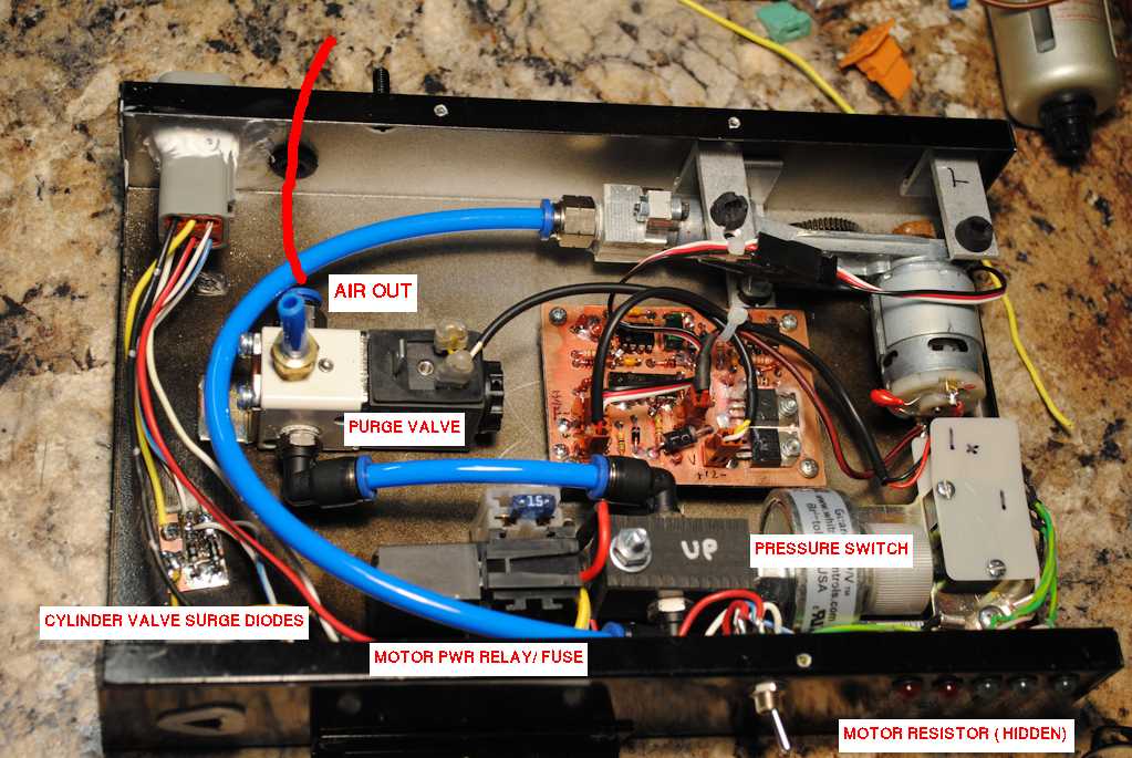
In the pump/control box:
This pump starts having issues when started with 6 volts against an existing 60 PSI head, if it happened to stop previously with the piston at bottom of stroke. But at 12 volts it will eat a finger trying to stop the crank gear from turning (don't ask) with 150 PSI head. I designed a speed control circuit that runs the pump at any set RPM I want, but will apply up to 12V if needed to get it up to speed. As speed increases toward target RPM it is regulated. Motor brush spark and motor temperature suggest it will tolerate this bit of abuse long after the pump piston/seal has worn out. (I used to build motor test equipment for R/C racing motors, as well as build and sell the motors themselves, lots of history with small motors). I setup the pump to run at about 3 volts when it has come up to my target RPM, which is about 1/2 of the Xiaomi Mijia's original speed, so it has little temperature rise at the cylinder/piston area, runs very quiet, but can stay ahead of shifter air consumption with hopefully longer life.
Operating the shifter, I get about 15 shifts before the compresser has to replenish the tank pressure - 55 to 70 PSI. This is with the assist cranked up to almost doing the shifts without ANY help from the driver (40 PSI at the cylinder). The pump will bring the empty reservoir (1/2 gallon) to 70 PSI in about 90 seconds.
Other stuff in the box - adjustable pressure sensor switch. The control circuit board also pulses the purge valve for about 1/4 second each time the pump starts. This helps purge any moisture collecting in the bottom of the reservoir tank (pump air goes in the bottom, supply air to the regulator out the top of the reservoir). The momentary pressure drop in the lines also reduced the demand on the pump itself slightly (minor plus). The pump is mounted on rubber grommets to further reduce noise. Ignition must be on to power the system but that circuit was a lower power fused circuit I already had available in the area I mounted this unit. A 20 amp fused line that was always "on" was also run back to this area before I installed the body, just for this sort of project... so the ignition on condition energizes an extra relay to power up the pump motor circuit. Various status LED indicators on the side of the box show what is going on with the system, along with a system enable switch to kill the whole toy. An input air filter on the bottom of the box lets air in for the pump suction.
.
.
All that is left is durability to be learned via school of hard knocks. Paddle shifters... a lot more to make that happen.
Last edited by aquillen; 02-16-2021 at 06:16 PM.
-
Post Thanks / Like - 0 Thanks, 4 Likes
-
02-16-2021, 06:31 PM
#325
If you are really that bored Art, I have a few projects I can sic you on.
Very nice as always.
-
02-16-2021, 07:21 PM
#326
Senior Member
Art... hope you don't mind.... I just sent your nomination for the Rube Goldberg award...
It all makes sense now...
Jet
-
02-16-2021, 07:28 PM
#327
Yes, I love Technology
I continue to enjoy my life time subscription to all of Rube's publications.
-
Post Thanks / Like - 0 Thanks, 1 Likes
-
11-02-2021, 07:09 AM
#328
Art,
I have been actively looking at your posts and others and I am fascinated what you have done with your build. Thanks for pointing to me in that direction. I am trying to digest the whole electrical section and the detailed drawings you put together. Can you clarify which ECM you used? Was it the JDM or USDM ECM from an Outback (Part number would help). I believe you baselined on a 2001 year for the electrical? Is that correct? Lastly, who fabbed your daughterboard for the TCM? Do you have that file to be fabbed?
More questions to follow as I did deeper into your build.
Thanks
Bill
-
11-02-2021, 09:32 AM
#329
Art,
Was wondering what you did for seatbelts? Did you use the OEM Subaru belts? I'm totally disappointed with the retraction of my OEM ones, and that is AFTER I sent them out to safety restore for new webbing and spring re-tensioning.
-Rob
-
11-06-2021, 03:08 PM
#330
Yes, I love Technology

Originally Posted by
maclonchas

Art,
I have been actively looking at your posts and others and I am fascinated what you have done with your build. Thanks for pointing to me in that direction. I am trying to digest the whole electrical section and the detailed drawings you put together. Can you clarify which ECM you used? Was it the JDM or USDM ECM from an Outback (Part number would help). I believe you baselined on a 2001 year for the electrical? Is that correct? Lastly, who fabbed your daughterboard for the TCM? Do you have that file to be fabbed?
Thanks
Bill
The JDM shop promised me an ECU but never found it. I used an Outback 2002, part # 22611AG79A . I also had a 2003 ECU and had it in the car but fuel pump relay would not work. Turns out the 2003 went with an electronic fuel pump controller module, not the relay. I think it was for less noise, more efficient setup. That changes the harness wiring of course, so rather than rip up my harness which was for the relay setup, I just popped in the 02 ECU and drove off. My custom version of the harness wiring is based on 2001 info for the most part.
I make my own PC boards unless buying a bunch or doing something commercial. Incredibly, the electronic version of my foil layout for the TCM adapter got lost... I had an old Win98 computer running an ancient board layout tool that I bought for megabucks in the early 90's and still love. I backed it up once in a while but it happened to lose the hard drive shortly after I did the layout for the TCM, and I had not backed it up. I've got it running on WinXP (yah, I know), but happy with it once more. Good news is I have a paper print of the foil and component views and can have that board laid out again i an hour - make 'em again.
My guess is you're not in a big hurry, and I've got some boards coming up to make for another project - could etch one then... a bunch of guys can tell you I haven't charged for stuff (pay back/forward).
-
11-06-2021, 03:14 PM
#331
Yes, I love Technology
Originally Posted by
roadrashrob
Art,
Was wondering what you did for seatbelts? Did you use the OEM Subaru belts? I'm totally disappointed with the retraction of my OEM ones, and that is AFTER I sent them out to safety restore for new webbing and spring re-tensioning.
-Rob
These came out of the back seat of an older Lexus 300 according to my notes, but didn't write down what year. They had sun fade after I got to looking closer, so I bought webbing and re-loaded them including sewing. Used heavy uphostery thread by hand - some may gasp but I'd bet the webbing rips anywhere by the time the sewing let loose. But the mounting had to be hacked and fiddled to fit, retraction with this is also funky - not really super happy with them either. I.e. can't really say these are your best solution. They are very low on my "make it better work list".
-
11-07-2021, 09:43 PM
#332
Art
Thanks. You are the man.
Bill
-
11-22-2021, 10:31 AM
#333
Originally Posted by
aquillen
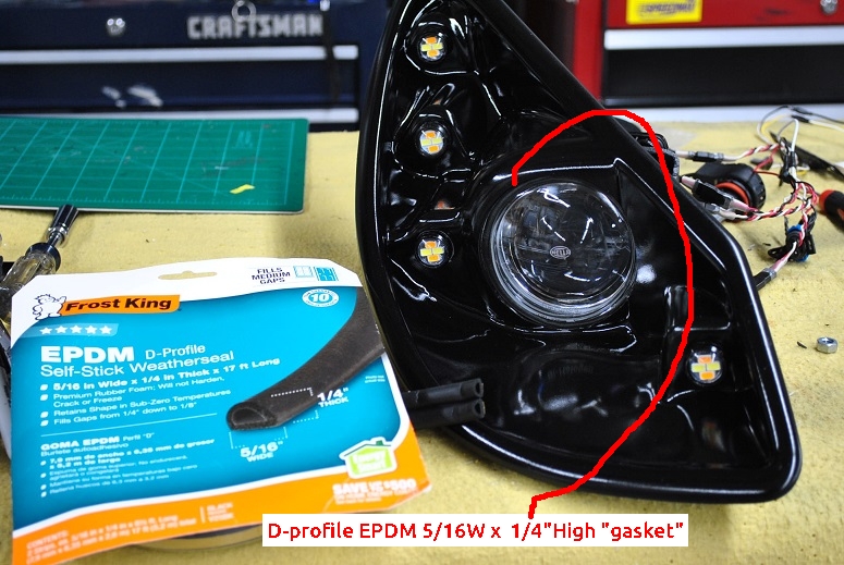
Here is my take on setting up the Hella's so they can be removed easily for service or whatever reason. I'm probably going to make some halo rings for the front, but still mulling that over... white SMT LED's embedded in transucent white plastic rings. When I get bored with the other items I'll probably go4it.
The Hella snap-in mounts go into my aluminum plates, mounted on studs. Can adjust the studs and of course the Hella adjusters too. I lost one of the bags of plastic Hella ball-snap thingies for a week. Chasing those on the Internet was a fiasco. Almost called Hella / and or / make my own then found the bag which had fallen into my throttle linkage scraps box. What a relief... I'm sure you all know that drill.
To get the low beam shutter cutoff pattern to be "level" to the road the lamps must be rotated. About 0.3" additional cut in the original plastic snap in holes gets the rotation needed for my build. In the original positions, the lamps are rotated so that the outside edge of the beams are higher on each side than the inside. I think it was 12 degrees give or take, but didn't write it down.
Still have some seal work to do, but there is no glueing of the lamp parts in this setup.
Art,
Curious how you ended up sealing off the Hella fixture from the bucket? Just worried about moisture getting on the inside, and then condensing on the lens. Was considering waiting until I perform a final aim of them, and then putting a bead of silicone around the gap. My "hope" was that the silicone would be flexible enough should minor adjustments be needed? But then again, given the surface area that would be in contact, so sure how much it would provide.
-rob
-
11-22-2021, 01:19 PM
#334
Senior Member

Not sure what Art did, but I was planning to do something similar to this thread.
https://thefactoryfiveforum.com/show...-and-Removable
-
11-22-2021, 01:26 PM
#335
Senior Member

Interesting headlight observations:
My european cars have low beam illumination "wings" to light-up road signs on the shoulder. The wing is on the pavement edge lens only so there are left side and right side driver configurations.
My Toyota lamps of all sorts are sealed and also vented to avoid fogging. The vent has an upside down rubber hose "U" so the vent aperture faces down.
jim
Last edited by J R Jones; 11-22-2021 at 01:28 PM.
-
11-22-2021, 04:01 PM
#336
Originally Posted by
fletch
Thanks Fletch. I actually had seen that thread via your posts, and like the method for sealing the exterior. My question is more around the backside where the Hella lamp fits into the headlight bucket. While it won't be exposed to the elements, it's still subject to humidity and condensation that could potentially form on the inside of the lens. Or so I think??
Headlight Seal.jpg
-
11-22-2021, 04:39 PM
#337
Yes, I love Technology
-
Post Thanks / Like - 0 Thanks, 2 Likes
-
11-22-2021, 05:13 PM
#338


 Thanks:
  Likes:


 Reply With Quote