-
06-02-2020, 10:29 AM
#121
Awesome work, gonna be one of a kind for sure! Have you finished mounting the Pinion Flange yet? In the same process myself, interested to see if you were able to close the gap on the dust cover.
-
06-02-2020, 03:20 PM
#122
Senior Member

Hi, yes I got the dust cover in place too. I answered your question on the other thread you posted, but I think what worked in my application may not be best applicable to your application.
Here's hoping I pull it all off and have a working one of a kind and not a fun looking static display 
Gen 3 Type 65 Coupe builder
-
06-09-2020, 08:18 AM
#123
Sorry, didnt see this until now. Just picked up my new pinion flange and shortened driveshaft from the axle shop. Had to modify the flange they found for me, should fit nicely now. But also had to shorten the driveshaft a bit. A little welding to be done on the frame, had to cut out a piece where the parking brake bracket sits, but in the end, if everything works out as intended, the engine will sit in the stock position.
-
06-09-2020, 09:24 AM
#124
-
07-29-2020, 03:30 AM
#125
Senior Member
-
Post Thanks / Like - 0 Thanks, 4 Likes
-
07-29-2020, 07:57 AM
#126
Senior Member

Not sure that's going to handle the G-forces with the PVC!
But seriously, great work. Going to need some serious fender flares.
John
-
08-04-2020, 02:11 AM
#127
Senior Member
Yep! Flares will be a necessity
Not car progress, but progress on the mill to make parts for the car. I've been getting things prepared for painting the mill and have most of the things masked off (ways, mating surfaces, fastener holes, etc) and now a paint booth set up with the parts inside.

I still need fans and filters in place before I can start though. Does anyone know what the setup should be for them? I think I remember the booth should be pressurized but I can't remember if the filters are for incoming air, outgoing, both, or what. I'm also not sure how to not have my driveway covered in mist and my neighbors not breathing in vapor or misted. Any help?
Gen 3 Type 65 Coupe builder
-
08-06-2020, 10:53 AM
#128
Senior Member

When I built my paint booth (still using it), I made it positive pressure. Two fans blowing in air, with filters, and then filters on the other side of the tent to let the air out. Incoming vents prevent dust from entering the booth, outgoing vents prevent overspray from ruining your garage/driveway. I went with positive pressure because I like the idea that if there were any small holes anywhere, it would push dust out rather than sucking it in. Seems to be working pretty well so far. The only hard part was figuring out how to create a doorway that was also sealed. I found some neat 7 foot long zippers (Home Depot) with adhesive sides that are used for creating zippered doorways in tarps— you just stick it on, unzip it, then cut the plastic in-between the zipper and then you have an instant, well-sealed, doorway.
Last edited by Alphamacaroon; 08-06-2020 at 11:02 AM.
Cheers,
--jim
Build 1: Gen III Type 65 Coupe, Gen II Coyote
-
08-06-2020, 11:55 AM
#129
Senior Member
Awesome, thanks for the info! I'll hunt for the zipper you're referring to. Seems a lot easier than making a door
Gen 3 Type 65 Coupe builder
-
08-06-2020, 12:48 PM
#130
Senior Member

Originally Posted by
q4stix

Awesome, thanks for the info! I'll hunt for the zipper you're referring to. Seems a lot easier than making a door
This is the one here: https://www.homedepot.com/p/Homax-7-...3142/206526231, but it also seems like there may be some better ones out there. It works really well when it's finished, but it was a bit of a pain to install— the sticker peel-off was really difficult to separate.
Cheers,
--jim
Build 1: Gen III Type 65 Coupe, Gen II Coyote
-
01-20-2021, 03:25 AM
#131
Senior Member
Reviving my own thread from the dead! Wow, didn't realize it's been so long since I've had a chance to make any real progress on things. Work has been full of challenges with projects, multiple late nights, and taking care of my own things too.
First up, I have the Bridgeport mill all painted and ready to start re-assembling. I was able to pick up a nice DRO and scales at an auction for a machining company going out of business. Hopefully those function well but too late to do anything about it now haha.

One of the work projects has been repairing and upgrading the electronics to a CNC machine in our shop. Since I took it on I've had to do lots and lots of wiring, re-writing code, installing circuit boards, contactors, etc. to get it going since the machine was fairly analog based with 80's era computer controls. As part of the proof I did things right, I have to test things each step of the way. Now that I'm able to run NC style g-code and I have the tool changer up and running, I dove in with my own test program and a big chunk of 4140 alloy steel I bought and brought in. Nothing like putting your money where your mouth is. Figure out which parts this block will be turning into.

As you can see, the tool paths all look smooth and consistent. Even after really ramping up the feed rates (450-500 SFM) for this machine and later finding a chipped carbide insert for some reason (these inserts can cut at 950 surface feet per min in steel), you can start to get a better idea of the parts in progress.

Sadly after this I'll resort back to my own resources since the testing phase of this CNC machine will be complete and it'll be put into true prototyping use.
Hopefully the updates will be a bit more frequent but I suppose that won't be hard to do after this long delay.
Gen 3 Type 65 Coupe builder
-
03-12-2021, 09:53 PM
#132
Senior Member
Clearly I haven't been posting as much as I'd like but that's also because I've been constantly busy with other things which means the coupe has taken the proverbial back seat (which it doesn't even have!).
As a new update, I finally have things basically ready to weld up one of the lower A-arms for the custom front suspension required for the all wheel drive. All that is left is fitting up the tubes to the CNC'd outer section and drilling the hole for the pushrod in the CNC part. Since the test machining wasn't on a 4 or 5 axis machine I couldn't just punch in that pair of holes without fixturing the parts another time in the machine. Easier to just do on a manual mill later when I don't have to worry about holding up other projects.


Gen 3 Type 65 Coupe builder
-
Post Thanks / Like - 0 Thanks, 1 Likes
-
03-13-2021, 09:54 AM
#133
Senior Member

This is one of my favorite build to follow. It's gonna be a very unique and awesome coupe when complete!
-
Post Thanks / Like - 0 Thanks, 1 Likes
-
03-15-2021, 02:35 PM
#134
Senior Member
Originally Posted by
Snowman
This is one of my favorite build to follow. It's gonna be a very unique and awesome coupe when complete!
Keyword "when" hahaha!
Gen 3 Type 65 Coupe builder
-
Post Thanks / Like - 0 Thanks, 1 Likes
-
03-19-2021, 08:34 PM
#135
Senior Member
And then there were two...

Now to start getting the uppers ready for welding and heat treat like the lowers.
Gen 3 Type 65 Coupe builder
-
Post Thanks / Like - 0 Thanks, 1 Likes
-
06-10-2021, 04:29 PM
#136
Senior Member
Now there are 4 A-arms and two push rods ready to be welded and heat treated. The sphericals locations will be bored out to after to allow for any distortion during heat treatment. The rod ends will come last.


I still need to make the upper mounting brackets or plates to allow for double shear on the bolts. After that it's upright / knuckle work. At the very least, when these are done it'll go a long way towards making me feel like I've had some real progress after such a long time.
Gen 3 Type 65 Coupe builder
-
Post Thanks / Like - 0 Thanks, 2 Likes
-
06-11-2021, 09:50 AM
#137
Senior Member
Those look great, not being an engineer myself how do you know what pipe size and wall thickness to use in a project like this?
John
-
06-11-2021, 01:21 PM
#138
Senior Member
John - There are a few different things that determine it. I estimated the loading based on the car weight, cornering loads, etc.
From there I knew the geometry of the suspension and I set up 'free body diagrams'.... basically coordinate systems that show where the load is going with angles and such. Next is solving some equations and getting loads in each part. From there it's standard formulas that take into account tube material properties, cross sections, fixity (pinned-pinned because of sphericals), and a few other things. I've also got a safety factor in there because of plenty of driving unknowns like bumps and potholes, encompassing my estimates, and more. Most properties were assuming an infinite fatigue life which is super conservative.
The upper arm is sized by lateral loading, the pushrod by axial loading and buckling capability, the lower arm turned out to be sized by bending because I couldn't attach the pushrod as close to the upright as I would have liked because the front half shaft was in the way.
It seems a little daunting at first but looking at it in single steps and chunks makes it not so bad
Gen 3 Type 65 Coupe builder
-
Post Thanks / Like - 1 Thanks, 2 Likes
-
06-12-2021, 07:54 AM
#139
Senior Member

This is my favorite build.
Hands down…
Chris
Generation 3 Type 65 Daytona Coupe Complete Kit #151885 received May 6, 2022. Gen 3 Coyote, IRS, Tremec TKX, American Powertrain hydraulic throwout bearing & Wilwood brakes.
MK4 Basic Kit #7404, 347 EFI - Pro M Racing ECM, 30# injectors, 70 mm throttle body, 80 mm MAF, Edelbrock Performer aluminum heads & RPM II intake, all new G-Force T5, 3:55 gears, Pro 5.0 shifter, 3-link, carbon fiber dash/custom Speedhut gauges and paint by Da Bat.
-
Post Thanks / Like - 1 Thanks, 0 Likes
-
06-16-2021, 02:51 PM
#140
Senior Member
Those are absolute works of art. It's almost a shame that they'll be hidden under the fenders. Almost.
Curious, how do you weld those? Do you just weld where they butt up, or do you drill a couple of holes or slots and fill weld so you get some joining where they overlap as well? I'm not a welder, so pardon if it's a stupid question 
Last edited by Alphamacaroon; 06-16-2021 at 02:57 PM.
Cheers,
--jim
Build 1: Gen III Type 65 Coupe, Gen II Coyote
-
06-17-2021, 02:44 PM
#141
Senior Member
Originally Posted by
Alphamacaroon
Those are absolute works of art. It's almost a shame that they'll be hidden under the fenders. Almost.
Curious, how do you weld those? Do you just weld where they butt up, or do you drill a couple of holes or slots and fill weld so you get some joining where they overlap as well? I'm not a welder, so pardon if it's a stupid question
No stupid questions, I'm learning a lot of things too!
There are two variants that I'm aware of. One is to do a butt weld (which I'll be doing with a chamfered edge on each part to form a V to fill) and the other is to do that plus a 'rosette' weld which is drilling further towards the end of the tube end insert and doing a filling weld (sometimes just the tube, sometimes both). I plan to just do a butt weld but may do the rosette last min.
Butt weld only

Rosette weld:

btw, going to send you an unrelated PM
Gen 3 Type 65 Coupe builder
-
06-18-2021, 05:59 PM
#142
Senior Member
Rosette weld— that's exactly what I was thinking! Now I know what to call it. Thanks!
Cheers,
--jim
Build 1: Gen III Type 65 Coupe, Gen II Coyote
-
06-30-2021, 09:04 PM
#143
Senior Member
-
Post Thanks / Like - 1 Thanks, 2 Likes
 WIS89
WIS89 thanked for this post
-
07-01-2021, 06:53 PM
#144
Senior Member
Pretty cool stuff as usual. It’s nice to have accomplished friends!
John
-
08-17-2021, 11:49 PM
#145
Phenomenal phenomenal build thread. Someone mentioned episodes on netflix, I feel the same way, only I don't watch TV. I prefer to spend my screen time reading amazing threads like this!
I almost feel bad inserting a Coyote question here (this thread really is like an art piece), but... like you I went with a gen 2 coyote and will go with an AEM Infinity (we chatted for a sec on the other forum). Question for you is: would you recommend going with the AEM harness and modifying that harness as needed? I've got no ECU at all right now... but figured what better way to start than by diving off the deep end??? I know you haven't been thinking about the Coyote lately, but mine just made it to Denver and am hoping to start some tinkering.
-
08-19-2021, 07:54 PM
#146
Senior Member
Originally Posted by
johnpinetree
I went with a gen 2 coyote and will go with an AEM Infinity (we chatted for a sec on the other forum). Question for you is: would you recommend going with the AEM harness and modifying that harness as needed? I've got no ECU at all right now... but figured what better way to start than by diving off the deep end??? I know you haven't been thinking about the Coyote lately, but mine just made it to Denver and am hoping to start some tinkering.
Hey! I haven't been able to be on the forums for 3 weeks so sorry if I missed a question on the other forum. Closer to back to normal now.
The AEM harness makes things really easy. Think of it as the equivalent as the Ford control pack harness for the Infinity. Both require the engine harness still. You can add in extra fuses and lines if needed too. I bought the Ron Francis harness with my kit before I knew about all the AEM harness stuff so I'm sure there is overlap between the two but that'll be ok. I didn't have to modify anything to get the engine running other than fixing a pin location mentioned in my earlier comments.
Gen 3 Type 65 Coupe builder
-
08-23-2021, 07:10 PM
#147
Senior Member
Progress on two fronts recently...
First, the Bridgeport is finally getting assembled in position!
Base first
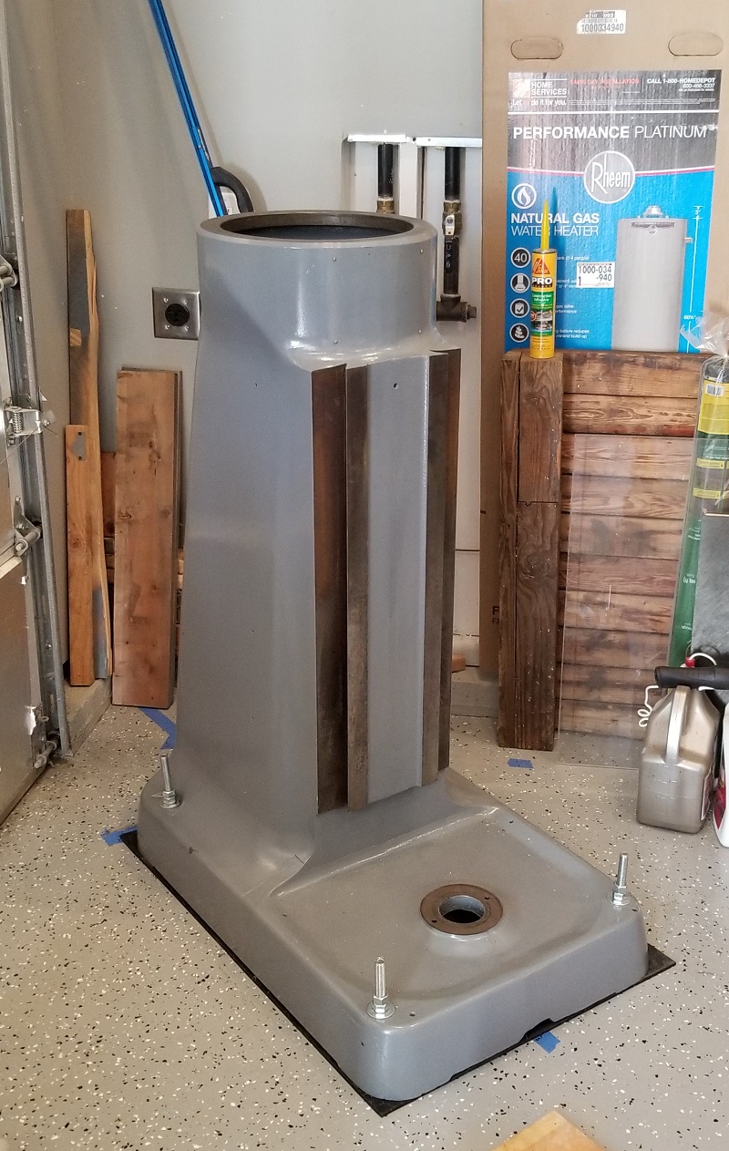
Then knee, turret, and ram. This accounts for a majority of the 'heavy' items. Once I replace the bearing in the knee that goes over the lifting screw, I'll be able to get the table put on. The head re-assembly will follow all of that.

Now for the front suspension update:
The arms and pushrods are back from heat treatment. At first I specified a minimum strength of 160ksi (160,000 lbs tension capability per square inch of material cross sectional area). I didn't specify a maximum because that was a fairly easy target to hit. I figured it'd come back around 180ksi. Turns out they figured they could skip tempering and that resulted in almost 240ksi. Way over the minimum so technically they met my requirements. Since stronger equals harder which equals less elongation and more brittle (in a relative sense, not like a ceramic brittle), I asked them to temper it lower. In the end it came out to 200-215ksi depending on the 4130 tubing and 4140 lug. Still has good elongation to prevent cracks due to bumps or road hazards but still strong enough to give me extra safety margin from what I calculated originally.
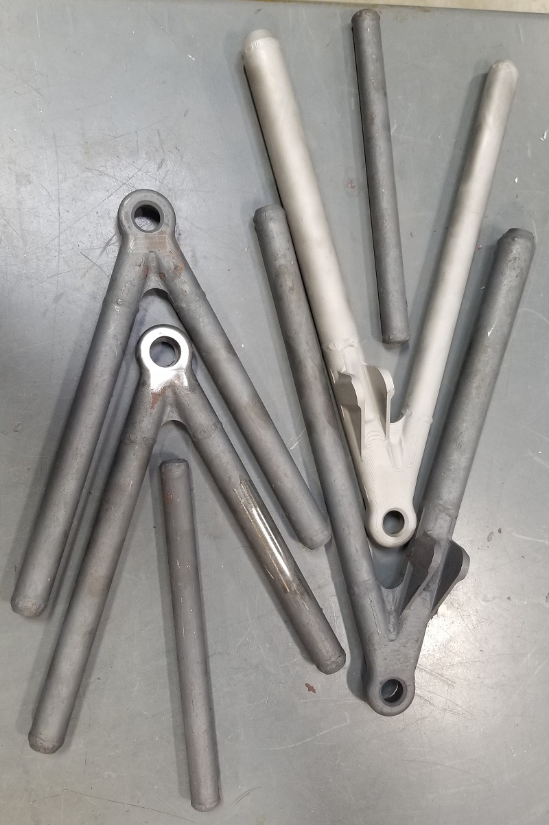
In this picture you can see where they removed the scale after quenching so they can do hardness testing (and calculate strength based on that). Look close and you'll see multiple, tiny dimples from the tester on the end and on the tube.

The dark arms are after heat treat, tempering, and quenching. The light is after a soft sand blasting to get the scale off. I don't think I'll polish or powder coat the arms but I will probably clear coat them after I solvent clean the outside to keep the metallic look but prevent rust on the alloy steel.

Next up is boring out the lug ends for the spherical bearings and grooving them for a snap ring. The lowers will also have the hole drilled for the pushrod rod end.
I'm also starting on the upright parts for the spindle, brakes, steering, etc.
Gen 3 Type 65 Coupe builder
-
Post Thanks / Like - 0 Thanks, 2 Likes
-
09-13-2021, 07:08 PM
#148
Senior Member
-
09-13-2021, 07:15 PM
#149
My Type 65 Coupe: Ordered May 27, 2021. Arrived November 19, 2021.
I would like to treat my gas pedal as a binary operator. It would be nice to get the cooperation of everyone in front of me.
-
11-12-2021, 08:05 PM
#150
Senior Member
-
11-12-2021, 08:06 PM
#151
Senior Member
-
11-18-2021, 06:44 PM
#152
Senior Member
Unbelievably mad skills - sooo nice!
Chris
Generation 3 Type 65 Daytona Coupe Complete Kit #151885 received May 6, 2022. Gen 3 Coyote, IRS, Tremec TKX, American Powertrain hydraulic throwout bearing & Wilwood brakes.
MK4 Basic Kit #7404, 347 EFI - Pro M Racing ECM, 30# injectors, 70 mm throttle body, 80 mm MAF, Edelbrock Performer aluminum heads & RPM II intake, all new G-Force T5, 3:55 gears, Pro 5.0 shifter, 3-link, carbon fiber dash/custom Speedhut gauges and paint by Da Bat.
-
Post Thanks / Like - 0 Thanks, 1 Likes
-
11-19-2021, 09:10 AM
#153
Senior Member
Very, very, very nice work!
Chris
Generation 3 Type 65 Daytona Coupe Complete Kit #151885 received May 6, 2022. Gen 3 Coyote, IRS, Tremec TKX, American Powertrain hydraulic throwout bearing & Wilwood brakes.
MK4 Basic Kit #7404, 347 EFI - Pro M Racing ECM, 30# injectors, 70 mm throttle body, 80 mm MAF, Edelbrock Performer aluminum heads & RPM II intake, all new G-Force T5, 3:55 gears, Pro 5.0 shifter, 3-link, carbon fiber dash/custom Speedhut gauges and paint by Da Bat.
-
Post Thanks / Like - 0 Thanks, 1 Likes
-
12-01-2021, 07:27 PM
#154
Senior Member
-
12-01-2021, 08:11 PM
#155
Senior Member
Generation 3 Type 65 Daytona Coupe Complete Kit #151885 received May 6, 2022. Gen 3 Coyote, IRS, Tremec TKX, American Powertrain hydraulic throwout bearing & Wilwood brakes.
MK4 Basic Kit #7404, 347 EFI - Pro M Racing ECM, 30# injectors, 70 mm throttle body, 80 mm MAF, Edelbrock Performer aluminum heads & RPM II intake, all new G-Force T5, 3:55 gears, Pro 5.0 shifter, 3-link, carbon fiber dash/custom Speedhut gauges and paint by Da Bat.
-
Post Thanks / Like - 0 Thanks, 1 Likes
-
12-10-2021, 02:56 PM
#156
Senior Member
-
12-10-2021, 05:33 PM
#157
Senior Member
Absolutely incredible!
Chris
Generation 3 Type 65 Daytona Coupe Complete Kit #151885 received May 6, 2022. Gen 3 Coyote, IRS, Tremec TKX, American Powertrain hydraulic throwout bearing & Wilwood brakes.
MK4 Basic Kit #7404, 347 EFI - Pro M Racing ECM, 30# injectors, 70 mm throttle body, 80 mm MAF, Edelbrock Performer aluminum heads & RPM II intake, all new G-Force T5, 3:55 gears, Pro 5.0 shifter, 3-link, carbon fiber dash/custom Speedhut gauges and paint by Da Bat.
-
12-11-2021, 09:22 AM
#158
Senior Member

I agree! Amazing skill!
Thank you for continuing to post your progress.
-
12-30-2021, 11:01 AM
#159
Member

Can't believe this is the first time I'm seeing this - incredible work!!
-
01-04-2022, 09:31 PM
#160
Senior Member
Thanks everyone!
No big news to report yet, but I've been trying to work to get the passenger side suspension to the same state that the driver's side is at.
Gen 3 Type 65 Coupe builder
-
Post Thanks / Like - 0 Thanks, 1 Likes


 Thanks:
  Likes:


 Reply With Quote

