Midwest Classic Insurance

Visit our community sponsor

Thanks Thanks:  0
Likes Likes:  0
Page 2 of 6 FirstFirst 1234 ... LastLast
Results 41 to 80 of 204

Thread: Frame Mods to Type 65 Coupe

  1. #41
    Trick Tool Maker, Super Moderator Hankl's Avatar
    Join Date
    Feb 2011
    Location
    Northern CA
    Posts
    671
    Post Thanks / Like
    Blog Entries
    1
    Quote Originally Posted by Timb View Post
    You need to issue a stronger jacket to this one
    Bad thing is, I keep encouraging Him!!

    Hank
    “If you didn’t have enough time to do it right the first time. How come you always have time to go back and do it again?” FFR1000186CP

    Understeer is when you hit the wall with the front of the car and oversteer is when you hit the wall with the rear of the car.
    Horsepower is how fast you hit the wall and torque is how far you take the wall with you.

  2. #42

    Join Date
    May 2011
    Location
    Pittsburgh, PA
    Posts
    729
    Post Thanks / Like
    Quote Originally Posted by loeffler1 View Post
    My only question is: What are you waiting to get hit by? a freight locomotive??

    Bill
    Bill,

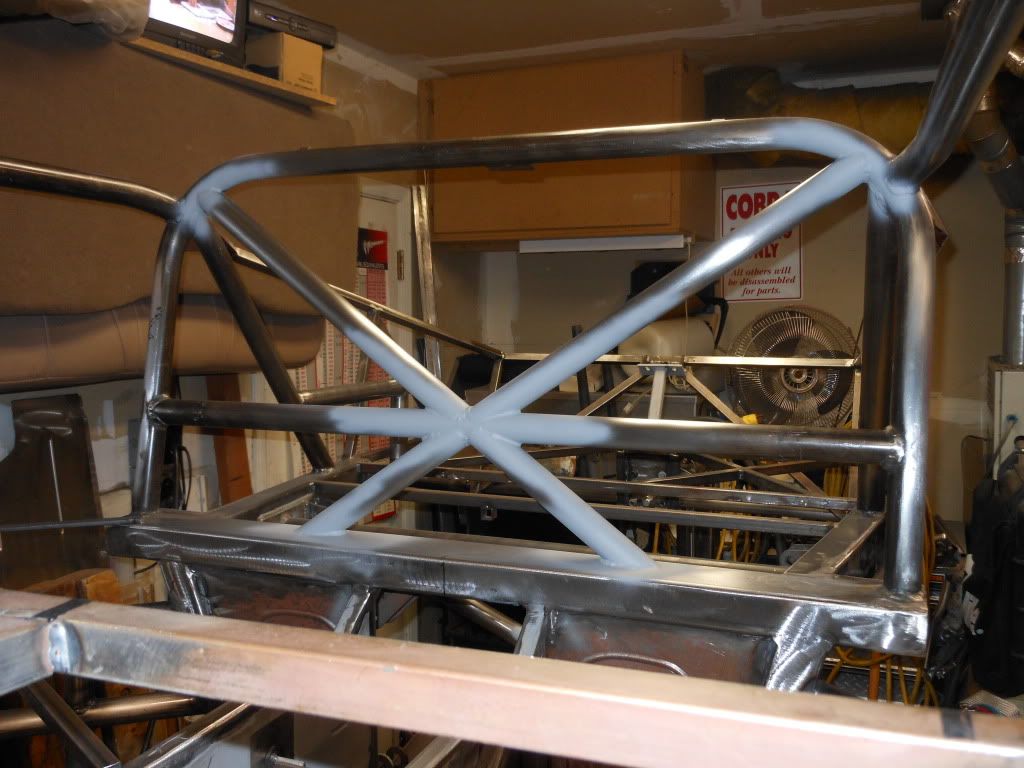
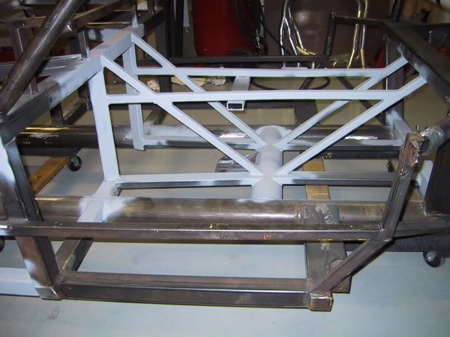
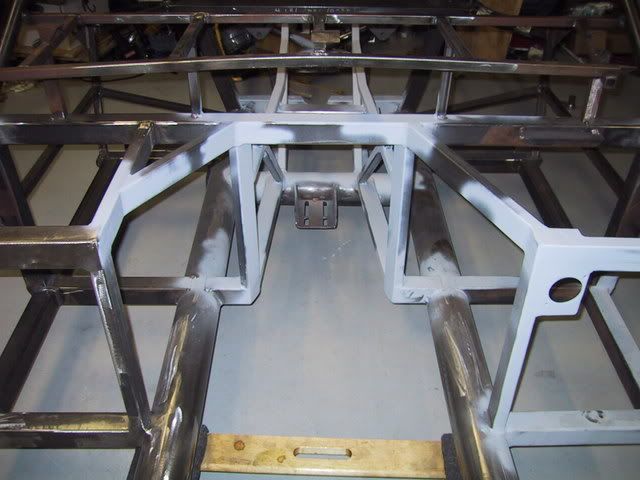
    For what it's worth, some of the mods I frankly doubt I would do again, but what's done is done. I don't think I'd do the diagonal brace between the front and back hoops again. The 2" square tubes in the front add a lot of weight, do not comply with SCCA rules because they are not DOM tube, and were a mind-numbing amount of work to install and make work with Wilwood pedals. So, if I did another car, I'd leave them as is, at 1", but I would install the tubes above them just as I did to comply with SCCA rules. The diagonal across the rear bars I'd probably do again. I really like the look of a complex tube chassis - it reminds me of my (now twice blown up) Ducati 900SS-SP. The little gussets I'd do again. The tube between the rear frame rails, maybe, maybe not.

    We'll see how it all works. I'm not too worried about it. I do have some plans to remove some of the weight I've added - the recipe involves Bon Ami cleanser, 99% isopropyl alcohol and a visit to a friend who builds tactical rifles for some machining. Other than the door bars, we're just about done.

  3. #43
    Senior Member CHOTIS BILL's Avatar
    Join Date
    May 2011
    Posts
    427
    Post Thanks / Like
    Blog Entries
    1
    Jacob, I have been thinking about your frame modifications and some are very good and some I am not sure about. All the frames I designed and built were a true space frame where as the coupe frame is a ladder type. The space frame places tubes at junctions with other tube which prevents the tubes from having bending loads where as the ladder frame uses thicker wall tubes to resist the bending loads from tubes placed in the middle of other tubes. I see you changed the center tube that joined the two roll hoops from being perpendicular to the roll hoops to being at an angle which I think will add much more tensional strength which is good but there are tubes just in front of the exhaust pipes, joining the front upper and lower frame tubes that I am not sure add much additional strength but if it were me I would model it and see. On all the frames I designed I made a 1/5 scale model out of 1/16” welding rods and soldered them together. I could then add or cut any tube and then try and flex the model and see if that tube actually helped or not. In places you can’t run a straight tube, such as the engine bay you can make a “Y” and join it to the frame at 3 places and make it removable for engine removal. Over all I would think your frame is much stiffer than it was but without real number it is hard know if it is over kill or not but generally stiffer is better.

    Bill Lomenick
    Chotis Bill

  4. #44

    Join Date
    May 2011
    Location
    Pittsburgh, PA
    Posts
    729
    Post Thanks / Like
    Bill,
    I appreciate your thoughts. I was going to run the additional tube across the front and back hoops at a much greater angle, just about from corner to corner, but installed it where I did to keep it out of the passenger's "head space." I'm also not convinced that the angled tubes in front of the headers are worth much. My sense is that I either need to cut them out and do another design, or complete the "X," for them to be fully effective. As it stands, I'm not sure that they're doing much.

    I was able to weld in some of the door bar uprights tonight and will post photos shortly. But in the meantime, here are 2 custom tools I fabbed up to work on the IRS differential - a pinion flange holder for setting the preload and a bracket that bolts to the diff cover holes and sits in a vice so you can work on the diff without it rolling around a work bench. I have never seen something like the diff holding bracket for sale, nor would I expect anyone to sell it, but it should make working on the center section much easier. I taped a piece of paper to the back of a diff and ran a pencil over it to outline the pattern, then transferred the pattern to the steel bracket and drilled/cut per the pattern.

    IRS Bench Mount 1.JPG

    IRS Bench Mount 2.JPG

    Pinion Holder Tool.JPG

  5. #45

    Join Date
    May 2011
    Location
    Pittsburgh, PA
    Posts
    729
    Post Thanks / Like
    Here are the pics of the lower uprights. They are 4" from the "saddle" of the cut to the bottom, and if I were to do this again I would make them 1/2" higher, which I think will make the aluminum behind the driver's seat a little easier to install. I placed them 7.25" apart, i.e., I measured 7.25" from the front vertical bulkhead and centered them every 7.25." After I clamped them down with the magnetic angles and the welding clamps I tacked the bottom of the tubes in 4 places. After they were tacked I removed the welding clamps and welded them in solid. Between the tacking at every 90 degrees and the clamps they did not apprear to "pull" when welded.

    P.S. Uprights - Tacked In.JPG

    In this pic you can see how far I spaced the door bars in from the top of the "rocker panel" tube - enough to get some aluminum interior sheel metal in there.

    D.S. Uprights - View From Above.JPG
    D.S. Uprights - Welded In.JPG
    D.S. Bar to Bulkhead Junction.JPG
    D.S. Uprights - Jigged in Place 2.JPG
    D.S. Uprights - Jigged in Place.JPG

    Welding the lower uprights in solid before fitting the lower door bar made that task very easy - just rest the bar on the uprights, rotate the end upwards until it hits the frame, and grind the rear edge until it is parallel with the frame rails. You can see in the pics how I used a level clamped below the frame as a reference point, and used a square as a 6 inch "go/ no go" gauge of sorts (4" for the uprights and 2" for the 2" frame rail). It wasn't quite idiot-proof, but it made the trimming very predictable. I just kept trimming the end of the bar until the square fit and the end was flat against the rear of the frame. The joint came out really tight (no daylight gets through). I beveled the edge pretty well and will weld it in shortly. Those who are familiar with the Coupe frame can see which bars I removed to make fitting these bars a little easier. I'm not entirely sure whether, and if so how, I will put them back in.

    Lower D.S. Bar - Fully Fitted 1.JPG
    Lower D.S. Bar - Fully Fitted 2.JPG
    Last edited by Jacob McCrea; 04-20-2012 at 04:47 PM. Reason: Typos

  6. #46
    Trick Tool Maker, Super Moderator Hankl's Avatar
    Join Date
    Feb 2011
    Location
    Northern CA
    Posts
    671
    Post Thanks / Like
    Blog Entries
    1
    Too Cool, I love it!!

    Hank
    “If you didn’t have enough time to do it right the first time. How come you always have time to go back and do it again?” FFR1000186CP

    Understeer is when you hit the wall with the front of the car and oversteer is when you hit the wall with the rear of the car.
    Horsepower is how fast you hit the wall and torque is how far you take the wall with you.

  7. #47
    Senior Member CraigS's Avatar
    Join Date
    Feb 2011
    Location
    Blacksburg, Va
    Posts
    4,730
    Post Thanks / Like
    I am glad to see that you put that roof bar in at an angle. Many yrs ago i did a minimal cage in a 280zx for scca IT and had just a square roof setup like your beginning. When i rolled it, the left front top corner moved toward me a little. No big deal,only about 2 inches.But I had rolled along a tire wall protected earth embankment so i think the impact was lessoned. I always thought that,if I did another similiar car, I would put in a diagonal. Great work on all the other improvements.
    FFR MkII, 408W, Tremec TKO 500, 2015 IRS, DA QA1s, Forte front bar, APE hardtop.

  8. #48

    Join Date
    May 2011
    Location
    Pittsburgh, PA
    Posts
    729
    Post Thanks / Like
    Thanks for the vote of configence, guys. Here are a few more pictures of recent progress. I got the lower bars and the top uprights welded in solid. As with the bottom uprights, I squared the top uprights on the lower bar with 90 degree magnets, then laid a tube over them to align them front-to-back, then clamped the whole mess in place with welding clamps and adjusted it with the carpenter's square in the pics until they were square with the frame. I made the process a little easier by grinding a "V" notch into both ends of the welding clamps so that they bit into the tubing, as opposed to sliding around and making me pull my hair out. If I did it again, I'd make both uprights 4.5," rather than 4" on the bottom and 5" on the top, as even measurements would look more uniform. If you go much higher than 4.5" on the bottom uprights, it makes it hard to weld around the 1" square body mount tube.

    On each side, I put an upright which was a few thousandths short in the middle, and put the perfect ones at the front and back. As with the lower uprights, having the top ones welded solid will make fitting the upper door bar much simpler - just place the top bar in place and rotate it upwards, then trim to fit. I elected to keep the bars inside the cockpit to reduce the need for fiberglass work, although I have some real concerns that interior space will be very tight compared to the Spec Coupe design. We'll see how it works out.

    Top Uprights Jigged in Place.JPG

    Top Uprights Jigged in Place 2.JPG

    Top Uprights Jigged in Place 3.JPG

    Top Uprights Jigged in Place 4.JPG

    Top Uprights Jigged in Place 5.JPG

    Top Uprights Welded Solid 1.JPG

    Top Uprights Welded Solid 2.JPG

  9. #49
    Trick Tool Maker, Super Moderator Hankl's Avatar
    Join Date
    Feb 2011
    Location
    Northern CA
    Posts
    671
    Post Thanks / Like
    Blog Entries
    1
    Good Job Jake!

    I don't think you've lost very much in the way of space compared to the Spec cage, the top bar is at waist height, so steering wheel placement will be OK.

    Hank
    “If you didn’t have enough time to do it right the first time. How come you always have time to go back and do it again?” FFR1000186CP

    Understeer is when you hit the wall with the front of the car and oversteer is when you hit the wall with the rear of the car.
    Horsepower is how fast you hit the wall and torque is how far you take the wall with you.

  10. #50

    Join Date
    May 2011
    Location
    Pittsburgh, PA
    Posts
    729
    Post Thanks / Like
    Thanks! Here are some pics of your excellent door bar design, fully implemented. I found it to be easiest to build the door bars in layers or levels, one on top of the other, and welding the lower level in solid before moving on to the next.

    A word of caution to anyone who may try this: save trimming to front of the bars until the very end. If you set up a sort of "go/no gauge," as I did in the photos, trim the end until the bar rotates into place, the back of the bar's contact point will move forward on the rear bulkhead as you remove material. So, save that step for last or you will end up with a bar that's too short to properly intersect with the rear vertical bulkhead. Here are the photos, which I think are self-explanatory. If it looks a little rough, it's because these are as-welded, without using a wire wheel to clean up the steel.

    Driver Door Bars 3.JPG

    Driver Door Bars 2.JPG

    Driver Door Bars 1.JPG

    In the photo below you can see that the top bar's bend is a little less sharp than the lower bar; the other side is also less sharp on top. Also, the top bar's bend point is a little farther back, perhaps an inch, to give a little more room between the top bar and the back of the seats.

    Driver Door Bars 4.JPG

    Passenger Door Bars 1.JPG

    Passenger Door Bars 2.JPG
    Last edited by Jacob McCrea; 04-25-2012 at 08:35 AM. Reason: Clearer wording

  11. #51
    Member jetsbaby's Avatar
    Join Date
    Feb 2011
    Location
    Chandler, A.Z.
    Posts
    85
    Post Thanks / Like
    I noticed that you did not angle the top bar out like Hank L did on his blog. Will this still have you pass NASA rules to run in what ever class you are going to run?? I hate to see you do all that work and not pass tech because you did not angle the top cage bar out..

  12. #52

    Join Date
    May 2011
    Location
    Pittsburgh, PA
    Posts
    729
    Post Thanks / Like
    As I read the NASA and SCCA door bar rules, I can't see how it would make a difference one way or the other. I deviated from Hank's design and kept the door bars entirely inside the interior space in order to minimize fiberglass work on the doors and body. What I've done will make ingress and egress more difficult, but hopefully it will motivate me to get to yoga class more and stay flexible.

  13. #53
    Senior Member rj35pj's Avatar
    Join Date
    Mar 2011
    Location
    Marion, IN
    Posts
    301
    Post Thanks / Like
    Quote Originally Posted by Jacob McCrea View Post
    As I read the NASA and SCCA door bar rules, I can't see how it would make a difference one way or the other. I deviated from Hank's design and kept the door bars entirely inside the interior space in order to minimize fiberglass work on the doors and body. What I've done will make ingress and egress more difficult, but hopefully it will motivate me to get to yoga class more and stay flexible.
    Just weld the doors shut and do it NASCAR style!!!!! In all seriousness I have trouble getting in and out of the normal opening, it will be more of a challenge with the higher bars.
    All of your frame mods look first class are you about done?

  14. #54

    Join Date
    May 2011
    Location
    Pittsburgh, PA
    Posts
    729
    Post Thanks / Like
    Yes, frame mods are just about done, thank goodness. After a year I am getting tired of metal shavings in my hair. I still need to do a mount on the front suspension X brace for a tow eye, touch up a few odds and ends with the welder, move the rear shock mounts to the outside of the frame rail, and figure out how I'm going to finish the front frame stiffening tubes. I now have half of an X up there on each side, which I doubt is that effective. I'll either finish the X, essentially making 4 triangles, or figure out another way to triangulate that area. I'm not goint to worry too much about the final design up there - it's not the Tacoma Narrows Bridge - but I'd like it to be as effective as reasonably possible.

    As for getting in and out, I am thinking that an inch lower door bar would make a big difference. As it stands, I think there's a quick release steering wheel and more yoga in my future.
    Last edited by Jacob McCrea; 04-26-2012 at 12:31 PM.

  15. #55
    Trick Tool Maker, Super Moderator Hankl's Avatar
    Join Date
    Feb 2011
    Location
    Northern CA
    Posts
    671
    Post Thanks / Like
    Blog Entries
    1
    Quote Originally Posted by jetsbaby View Post
    I noticed that you did not angle the top bar out like Hank L did on his blog. Will this still have you pass NASA rules to run in what ever class you are going to run?? I hate to see you do all that work and not pass tech because you did not angle the top cage bar out..
    As Jake said, the rules don't say either way what the angles of the bars should be, we just adhere to the structural necessities of the structure. That cage should pass any sanctioning bodies rules.

    Hank
    “If you didn’t have enough time to do it right the first time. How come you always have time to go back and do it again?” FFR1000186CP

    Understeer is when you hit the wall with the front of the car and oversteer is when you hit the wall with the rear of the car.
    Horsepower is how fast you hit the wall and torque is how far you take the wall with you.

  16. #56
    Senior Member smithtlw's Avatar
    Join Date
    Feb 2011
    Location
    Brockport, NY
    Posts
    103
    Post Thanks / Like
    From the clip of the rules posted it looks like there is no height specified of the door bars. Is that the case? How do you determine how high they must be?

    Todd
    Last edited by smithtlw; 04-26-2012 at 03:34 PM. Reason: added clarity

  17. #57
    Member Daytona Dan's Avatar
    Join Date
    Apr 2011
    Posts
    59
    Post Thanks / Like
    Looks great man. I agree NASA/SCCA should be fine with what you've done. By choosing to minimize the door work you only lost a couple inches of elbow space and potential crush zone. That said, nothing's going to crush your cage! You'll be fine in and out...I am 6' 1" and able to get in and out with the door closed. The bars are actually very easy to slide in on and sit on as you exit normally. I removed my windows and scoops last season to make sure I wouldn't have an issue getting out in a hurry. Just added a window net to keep my arms inside should I get into a rollover situation. I forget, did you do a center roof bar? I got the idea from that extended wheelbase Coupe last year, and I think the West Coast team might be adding one now.

  18. #58

    Join Date
    May 2011
    Location
    Pittsburgh, PA
    Posts
    729
    Post Thanks / Like
    Todd,

    I'm honestly not in a great position to answer that and would defer to the Spec Coupe builders and others who have gone through the process of getting an SCCA or NASA logbook. I will say that neither rule book has an explicit height requirement, but in my view common sense should dictate that they be high enough to do their job. My door bars are 12" tall (4" lower verticals, 5" upper verticals, and 3" worth of tube (1.5" x 2 bars). Assuming that the outside frame rail sits 4" from the ground, plus 2" for the rail itself, plus 12" for the door bars, we are at 18", which should provide plenty of protection from anything I'd encounter on a track, or for the most part, on the street. I'll defer to Hank on this, but I understand that the height was set to provide protection from, say, a side impact from a Ford Super Duty.

    For what it's worth, and I know this isn't responsive to the question, but with this design you can only make the top bar a little higher before it becomes difficult to get a proper angle on a mig gun at the rear of the top bar's junction with the frame, assuming you want to keep the bars parallel with each other. There are ways to work around this if someone wanted use this design and have a higher door bar.

    Dan,

    Thanks for the compliments. I did a center roof bar, but installed it at an angle. There are some photos early in the thread. The bar is actually removable with Ballistic Fabrication connecting lugs so I can pop it in and out with 4 Allen bolts and see if it makes a difference. The angle is a compromise between wanting to take full advantage of the strength of a triangle and wanting to keep the bar out of my passenger's head space since the car will also be used on the street.
    Last edited by Jacob McCrea; 04-26-2012 at 05:01 PM. Reason: Typo

  19. #59
    Trick Tool Maker, Super Moderator Hankl's Avatar
    Join Date
    Feb 2011
    Location
    Northern CA
    Posts
    671
    Post Thanks / Like
    Blog Entries
    1
    Quote Originally Posted by smithtlw View Post
    From the clip of the rules posted it looks like there is no height specified of the door bars. Is that the case? How do you determine how high they must be?

    Todd
    Todd,

    What we were told, is that the preference of the sanctioning bodies was that the bars cover at least 2/3's of the door opening, that in of itself leaves some room for interpretation. The way we worked it out, was to take a measurement of the door opening, not from the sill bar, but from the lower frame rail. From the frame rail to the top of the forward bulkhead is approxmatly 16 1/2", 2/3's of that is 11". We measured several cars that were in the area, and found that most bumpers started at anywhere from 12" to 20", and terminated at 16" to 26" in height(From Hondas to 4x4 Ford Expeditions). With a ground clearance of 4", 4" of distance from the bottom of the 4" tube to the top of the frame rail, and then 11" upwards from there we reached 19" for the top of the upper SIB (Side Intrusion Bar). Any higher, and it starts to become problematic for entry and exit. We moved the top bar outward to negate some of the entry/exit problem, as it ends up providing a little more room to the driver to pivot their body into to the car as they slide in.

    Hank
    “If you didn’t have enough time to do it right the first time. How come you always have time to go back and do it again?” FFR1000186CP

    Understeer is when you hit the wall with the front of the car and oversteer is when you hit the wall with the rear of the car.
    Horsepower is how fast you hit the wall and torque is how far you take the wall with you.

  20. #60
    Member
    Join Date
    Feb 2011
    Posts
    30
    Post Thanks / Like
    Hank,
    Cant wait to see the treatment of the bars with the doors. That should be quite interesting.

    Jacob,
    Your mods are very interesting as well.
    Jim

    CP 438, FR 347, TKO 600, Levy/Wilwood 6P/4P

  21. #61
    Senior Member smithtlw's Avatar
    Join Date
    Feb 2011
    Location
    Brockport, NY
    Posts
    103
    Post Thanks / Like
    Hank - Thanks for the clarification.

    Jacob - Your work is outstanding and I appreciate you sharing all the detail. The only bad thing is that I haven't started yet and you are adding time to my build with all of these great ideas. I have a bare chassis as I need to do some bumper mods for NYS. As long as I am doing some frame mods...

    Todd

  22. #62

    Join Date
    May 2011
    Location
    Pittsburgh, PA
    Posts
    729
    Post Thanks / Like
    Quote Originally Posted by smithtlw View Post
    As long as I am doing some frame mods...

    Todd
    Thanks Todd. I laughed when I read that; that's how this got started for me as well, and I have quite a few here to thank for leading me astray. I think you are in for a lot of fun; there is something about these cars (i.e., FFRs in general) that really lets builders get creative. If you ever want to touch base about what I'd do differently, send me a PM and I'd be happy to discuss any aspect of the build.

    Also, here is what I just completed. I used some of the 1" square tubing that I cut off of the frame to complete the "X" that was previously half-complete. I can't say I know a lot about structural engineering, but I do know that triangles are pretty stiff, so I added some tubing to triangulate the chassis stiffening tubes that I added. I'd guess it's pretty strong. Whether it is worth the extra weight, I can't say, but I will say that I'll be looking for any way I can to shave weight as the build progresses. When I get a few minutes I'll edit this post and add a narrative explaining how I got the X straight as an arrow. For now, here are the pics.

    Here is what I used to model where the tubes would intersect: a piece of 1" wide flat stock. I put it where I wanted the tube to go, marked all 3 connecting points with a Sharpie and clamped it in place.
    Guide for X Bar 3 .JPG

    I used a Starrett angle measuring tool, as well as an angle measuring tool from Van Sant Enterprises, to figure out the angles.

    Passenger Half Bar.JPG

    I cut all 4 tubes where they intersect with the diagonal tube at the same time with a JD Squared Notchmaster tubing notcher. I believe that this tool is well worth the extra $100 above the basic notchers because it will accept flat stock and square tubes, rather than just round tubes. Notching all 4 tubes at the same time lets you make all 4 angles the same, which in turn makes fitting them to the diagonal bar that much easier.

    Once one tube was welded in place I took a piece of 1.5" steel angle, notched it in the middle, and used it as a jig for the other tube.

    Passenger Half Bar 2.JPG

    Because it was a little chilly in my shop, and because I was welding .120 tube to the thinner square tube, I preheated the thicker tubes with a torch - just enough to burn off the moisture and render them too hot to touch with a bare hand. In my uneducated opinion, this will let the weld melt into the thicker tube a little better, without the need to adjust the welder so high that you either risk blowing holes in the thinner tube or have to move the gun too quickly to make a nice bead.

    Passenger Half Bar 3.JPG

    Passenger X Bar .JPG

    Passenger X Bar 2 .JPG

    Passenger X Bar 3 .JPG
    Last edited by Jacob McCrea; 05-01-2012 at 08:55 PM.

  23. #63
    Senior Member rj35pj's Avatar
    Join Date
    Mar 2011
    Location
    Marion, IN
    Posts
    301
    Post Thanks / Like
    Jacob,
    I look forward to seeing you modify the aluminum to fit your frame mods. I hope you supply the same detailed photos.
    Keep up the great work!
    Bob

  24. #64
    Senior Member CraigS's Avatar
    Join Date
    Feb 2011
    Location
    Blacksburg, Va
    Posts
    4,730
    Post Thanks / Like
    It is interesting to me that you have ended up w/ a lot that is similiar to David Borden's roadster build. He also used CAD (Solidworks I think) to design his. Search the other forum for his long build thread.
    FFR MkII, 408W, Tremec TKO 500, 2015 IRS, DA QA1s, Forte front bar, APE hardtop.

  25. #65

    Join Date
    May 2011
    Location
    Pittsburgh, PA
    Posts
    729
    Post Thanks / Like
    Bob, yes, I will keep the photos coming! I would feel bad if I did not show the challenges involved with making the aluminum fit.

    Craig, yes, I've studied David's frame mods many times and they are excellent. I've incorporated some of what he has done into this car, especially the footbox-to-front suspension tubes, and if I had to do it all over again I would probably follow his front end mods a little more closely as he has actually done a real engineering-based analysis, while I have not.

    Here are a few more pics of some of the tools I used, which will give sense of how I figured out angles, tube lengths, etc.

    I notched my welding clamps as shown before I did the door bars, which allowed them to really get a good bite on the tubes and keep them solidly in place while welding. It allowed me to really clamp them down and prevent the tubes from pulling from the weld cooling.
    Notched Welding Clamp.JPG

    Here is a pattern I made showing a bent 1.5" diameter tube with a 5.5" center line radius, which helped me to see and figure out where on the tube the bend should start.
    Curve Template.JPG

    The two photos below show how I needed to move the bend point on the top tube back a little and/or make the bend less sharp to make it intersect the bulkhead at the same spot as the lower bar.
    Angle Finder on Top Door Bar 2.JPG

    Angle Finder on Top Door Bar.JPG

    The JD Squared Model 32 bender, which reminds of Archimedes' saying about being able to move the earth with a long enough lever and a place to stand.

    Tube Bender.JPG

    The angle finder from Van Sant on the front frame tubes.
    Angle Finder on Lower Front Tube.JPG

  26. #66
    Trick Tool Maker, Super Moderator Hankl's Avatar
    Join Date
    Feb 2011
    Location
    Northern CA
    Posts
    671
    Post Thanks / Like
    Blog Entries
    1
    Jake,

    Great changes, I'll give you a call tonight!!

    Hank
    “If you didn’t have enough time to do it right the first time. How come you always have time to go back and do it again?” FFR1000186CP

    Understeer is when you hit the wall with the front of the car and oversteer is when you hit the wall with the rear of the car.
    Horsepower is how fast you hit the wall and torque is how far you take the wall with you.

  27. #67

    Join Date
    May 2011
    Location
    Pittsburgh, PA
    Posts
    729
    Post Thanks / Like
    More pictures of recent progress:

    I put this little piece of 1" x .120 flat steel in place of the old 1" square tube to give myself another solid point back there for attaching the interior aluminum.

    New Side Piece.JPG

    New Side Piece 2.JPG

    I moved this center tube back in case I want to install a mid-shifted Tremec at some point in the future. For now the donor car's T-5 will have to suffice.

    Old Cross Bar.JPG

    New Cross Bar.JPG

  28. #68
    Junior Member McMahonRacing's Avatar
    Join Date
    Feb 2011
    Location
    Danville NH
    Posts
    9
    Post Thanks / Like
    A suggestion ..... since you are fabbing so much, a thought might be to drop you seat in and see just how much room you have in relation to the trans tunnel ..... on my spec chassis ( modded ) I wish I had trimmed the trans tunnel back further & really wish I had made it removable ...... on my next chassis ( custom job under a Cobra skin ) I will be doing both for sure, benefits:
    Trans. & engine removal ( been thru 3 motor / trans swaps already )
    Trans service
    Clutch area acess
    Sharp straight edges can be tailored ( can't begin to tell ya how many tines I have bumped a knee or elbow or on an edge )

    Anyway, just something to think about.
    I do like it by the way !!!!!!

  29. #69
    Trick Tool Maker, Super Moderator Hankl's Avatar
    Join Date
    Feb 2011
    Location
    Northern CA
    Posts
    671
    Post Thanks / Like
    Blog Entries
    1
    Just to let you guys know, Jake isn't having all this fun alone. My Coupe is one of the 1st Gen, and didn't come with a cross bar for the rear hoop.
    Instead of installing what FFR has, I checked the rules and did this instead. The "X" configuration allows for the passenger to have a properly installed
    shoulder harness that will sit properly with a HANS device.


    And to the "Sharp straight edges can be tailored" comment, I did extensive mods to the trans tunnel for the mentioned reason,
    and to change the slant of the tunnel. It also ended up in making the passenger and drivers sides symmetrical width wise, as they are not from the factory.


    Hank
    Last edited by Hankl; 05-27-2012 at 10:17 AM.
    “If you didn’t have enough time to do it right the first time. How come you always have time to go back and do it again?” FFR1000186CP

    Understeer is when you hit the wall with the front of the car and oversteer is when you hit the wall with the rear of the car.
    Horsepower is how fast you hit the wall and torque is how far you take the wall with you.

  30. #70
    Junior Member McMahonRacing's Avatar
    Join Date
    Feb 2011
    Location
    Danville NH
    Posts
    9
    Post Thanks / Like
    Actually that open top or removeable top is a much simpler design, esp. since you modded the side fit prior .... my just have to put that on the list for this winter ( my alum. trans tunnel cover is 1/8" & removeable but would be easy enough to cut the center 1" supports out and build a removeable unit for service - boy would that make my life easier ) .... very nice job boys !!!!!!

  31. #71

    Join Date
    May 2011
    Location
    Pittsburgh, PA
    Posts
    729
    Post Thanks / Like
    ^Thanks for the compliments. I will give serious thought to making the top of the transmission tunnel removable. I understand that getting the transmission out without removing the engine is not easy. The routine I've read is something like "pull it back as far as you can, twist it sideways 90 degrees, throw salt over your shoulder, say a prayer, tip the front end down, and maybe it will come out." I'm exaggerating with the salt and prayers, but still, from what I've read it's a hassle.

    Maybe making those square 3/4" triangulating bars on the top bolt in and out with, say, 1/4-20 bolts and riv-nuts, along with making the top panel removable, would accomplish this pretty easily. Or, as wisely suggested, get rid of the triangulating bars entirely and go with a thicker top cover.

  32. #72
    Junior Member McMahonRacing's Avatar
    Join Date
    Feb 2011
    Location
    Danville NH
    Posts
    9
    Post Thanks / Like
    Purpose of the 1/8" top in my case = it is a step & offers a touch more protection to me in case of trans./driveshaft/ etc issues.

    Triangle racing, I suspect that w/ a fully caged / halo car you really don't need it = when I mod mine this winter I will keep it and make it bolt in prob. w/ thru bolts ( button head allen's ) in say 6 places ( in my case it is more to get the angle of the trans "up" too ease install w/ the motor.

    As w/ anything, it is just a thought & I did have a pic several yrs back of a drive shaft/u-joint failure in an FFR that took all the alumn. out and even got into the seat area of the driver, kinda why mine is over laid for driver protection.

    Ever have any questions or want to nose around & youre in NH fel free to drop me a note @ swing in .... you might find some of the stuff interesting.

    Pat

  33. #73
    Senior Member xlr8or's Avatar
    Join Date
    Feb 2011
    Location
    San Diego CA
    Posts
    316
    Post Thanks / Like
    Quote Originally Posted by Jacob McCrea View Post
    ^Thanks for the compliments. I will give serious thought to making the top of the transmission tunnel removable. I understand that getting the transmission out without removing the engine is not easy. The routine I've read is something like "pull it back as far as you can, twist it sideways 90 degrees, throw salt over your shoulder, say a prayer, tip the front end down, and maybe it will come out." I'm exaggerating with the salt and prayers, but still, from what I've read it's a hassle.

    Maybe making those square 3/4" triangulating bars on the top bolt in and out with, say, 1/4-20 bolts and riv-nuts, along with making the top panel removable, would accomplish this pretty easily. Or, as wisely suggested, get rid of the triangulating bars entirely and go with a thicker top cover.
    Yeah.. It's actually twist it 90 and pull it back as far as you can, twist it another 90 and dump out all the remaining fluid on your then pull back farther, then dip the nose and twist it back the other way as you forward. Finish with cleaning all the trans fluid out of your hair, ears, eyes, etc.

    It's never too early to start beefing up your obituary.

  34. #74

    Join Date
    May 2011
    Location
    Pittsburgh, PA
    Posts
    729
    Post Thanks / Like
    Happy Memorial Day to the many veterans on this forum and beyond!

    Attached are a few recent progress photos. I followed Pat M.'s excellent suggestion above and cut out the 3 square tubes at the top of the trans tunnel. I'll make new ones out of aluminum and make them bolt in so that the transmission can come out through the top or the bottom without the mess Scott describes above.

    Removed Center Tubes.JPG

    Here is the mount I made for the front tow eye, following Scott's excellent design. It's 3" wide, 3/16" cold rolled steel. I set it up pretty far to the outside so that the bolt-on eye I'll make is as short and, therefore, as light and strong, as possible.

    Front Tow Eye Mount.JPG

    This shows how I set up a square to get the mount to sit perpendicular to the frame.

    Front Tow Eye Mount 2.JPG

  35. #75

    Join Date
    May 2011
    Location
    Pittsburgh, PA
    Posts
    729
    Post Thanks / Like
    And here are some new photos of Hank's alternative outboard shock mounts, as implemented on my car. The material is 3/16" cold rolled steel plate.

    In this photo you can see 1 of 2 pieces of tube I used to set the spacing perfectly during welding/assembly.

    New Shock Tower 1.JPG

    Just sitting there, before final fitting.

    New Shock Tower 2.JPG

    This handy tool from Van Sant was used to set the top of the shock towers parallel with the plane of the lower control arm. And yes, I know that lower control arm is on the wrong side. It didn't matter for purposes of setting the angle of the shock tower.

    New Shock Tower 3.JPG

    New Shock Tower 4.JPG

    I like to clean the metal with DX440 immediately before welding. This is also the strongest wax and grease remover for auto body work I've ever used.

    New Shock Tower 5.JPG

    I used this piece of 1" steel to set how far away from the bulkhead I placed the towers.

    New Shock Tower 6.JPG

    I tacked the mounts in place at 4 spots, checked them again while they cooled, then welded them solid. Tacking at a few spots, waiting just a little, then welding everything solid seems to prevent the pieces from pulling as the weld cools.

    New Shock Tower 9.JPG

    New Shock Tower 8.JPG

    You can see how the heat-affected zone grows as the weld goes from top to bottom.

    New Shock Tower 7.JPG

    New Shock Tower 10.JPG


    Hank and I have a few more tricks up our sleeve to make the IRS better able to handle heavy track duty. Stay tuned for those mods!
    Last edited by Jacob McCrea; 06-20-2012 at 10:29 PM.

  36. #76
    Senior Member rj35pj's Avatar
    Join Date
    Mar 2011
    Location
    Marion, IN
    Posts
    301
    Post Thanks / Like
    Jacob,
    You have such a work of art going on here maybe you should just forget about the body.

  37. #77
    Senior Member CraigS's Avatar
    Join Date
    Feb 2011
    Location
    Blacksburg, Va
    Posts
    4,730
    Post Thanks / Like
    As long as you are redoing the irs why not get rid of the ffr arms altogether. There are a million pics of formula and sports racers from maybe the 80s that you could model arms after and make them easily adjustable as well. I say the 80s to stay away from cantlever coilovers etc.
    FFR MkII, 408W, Tremec TKO 500, 2015 IRS, DA QA1s, Forte front bar, APE hardtop.

  38. #78
    Super Moderator vnmsss's Avatar
    Join Date
    Feb 2011
    Location
    California
    Posts
    649
    Post Thanks / Like
    Blog Entries
    13
    Jacob....It's awesome that you and Hank are carrying the torch forward in making additional improvements to the IRS system. You know though, that all of these new mods are just reinforcing Hank's designation as "The Never-Ending Builder."

    Hank.....I should've know when you two got together that there'd be metal shavings and sparks flying......You're on a timeline, man!! We have a hot date on-track this summer!!!

    Love what you guys are doing!!!

    Karen
    #28 FFR Challenge Series
    #28 FFR Type-65 Coupe
    2011 Western Endurance Racing Championship
    2010 West Coast Champion
    Drive it.....Like you stole it!

  39. #79
    Trick Tool Maker, Super Moderator Hankl's Avatar
    Join Date
    Feb 2011
    Location
    Northern CA
    Posts
    671
    Post Thanks / Like
    Blog Entries
    1
    Quote Originally Posted by CraigS View Post
    As long as you are redoing the irs why not get rid of the ffr arms altogether. There are a million pics of formula and sports racers from maybe the 80s that you could model arms after and make them easily adjustable as well. I say the 80s to stay away from cantlever coilovers etc.
    Craig,

    While there are plenty of new parts that could be used out there, reinventing the wheel is not necessarily a good option for us. Part of the exercise is to make sure that we keep the cost of making the mods down. If a part is well designed and serviceable, there is no real need to change it.
    As to the IRS, I feel that with a few tweaks we can improve on the function and robustness of the system. You also have to take into consideration what you would have to change to make another design work, mounting points, shock location(Which we have already changed), knuckle type,
    axle length, etc, you change one or two things, and then the Domino effect starts, question is, how much time and money will you end up throwing at the project? The focus is to make the system stronger, and hold up under conditions that the original designers of the system did not expect
    us to exceed, plus a cad plated new part here and there doesn't hurt either!!

    Hank
    “If you didn’t have enough time to do it right the first time. How come you always have time to go back and do it again?” FFR1000186CP

    Understeer is when you hit the wall with the front of the car and oversteer is when you hit the wall with the rear of the car.
    Horsepower is how fast you hit the wall and torque is how far you take the wall with you.

  40. #80
    Member Daytona Dan's Avatar
    Join Date
    Apr 2011
    Posts
    59
    Post Thanks / Like
    Quote Originally Posted by vnmsss View Post
    Jacob....It's awesome that you and Hank are carrying the torch forward in making additional improvements to the IRS system. You know though, that all of these new mods are just reinforcing Hank's designation as "The Never-Ending Builder."

    Hank.....I should've know when you two got together that there'd be metal shavings and sparks flying......You're on a timeline, man!! We have a hot date on-track this summer!!!

    Love what you guys are doing!!!

    Karen
    Hank, can you also address the elephant in the room...when are we going to see you out on the track man? I know we all are looking forward to seeing you out there enjoying the fruits of your passionate labor! Don't make me...no, do make me come out there!

Page 2 of 6 FirstFirst 1234 ... LastLast

Posting Permissions

  • You may not post new threads
  • You may not post replies
  • You may not post attachments
  • You may not edit your posts
  •  

Replica Parts

Visit our community sponsor