
Visit our community sponsor

Thanks:
0

Likes:
0
-
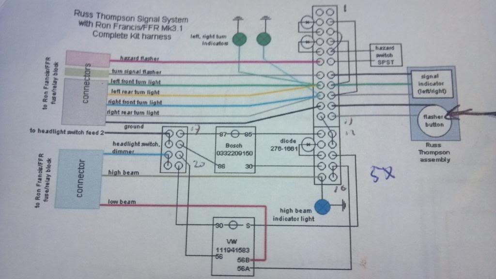
Russ Thompson Turn Signal Wiring with Horn Button
I've read through JDAV's wiring thread and all the comments so many time that the schematic is actually starting to make sense. Thanks to all who contributed. Can't tell you how many times I've looked at all of the different diagrams and come away frustrated.
I haven't decided yet but I might want to wire the momentary switch on the Russ Thompson column to the horn button rather than flash to pass.
1. I've read that wiring the momentary switch to the horn requires a relay. I know what a relay does but I don't know how to spec one out or order one. Does anyone have a part number or can you tell me what to ask for?
2. Here's where a little knowledge makes me dangerous. If I'm not doing the flash to pass wiring, can I delete the lower half of this schematic? No VW or Bosch relay?
3. Would I just need the two diodes and a relay for the horn? Then wire the high beam/low beam toggle per the RF instructions?
-Steve
-
Senior Member

If you're going to use the momentary switch for the horn and wire the high/low beam with a dash mounted switch, then ditch the wiring diagram completely. You don't need it! Assuming you have the RF harness, (1) It already has a relay on the horn. You don't need to add another one. There are two wires in the dash harness for the horn. BRN-HORN SW and BLK-HORN SW GRND. Hook those to the RF momentary wires and honk away. (2) Wire the dimmer switch exactly like shown in the RF schematic. As long as it's an appropriately rated switch (like the one in the kit) it will work without any additional relays. (3) Wire the RF turn signal wires the same way as the SPDT switch showing in the RF schematic. It's exactly the same thing. You don't need any added diodes as long as you use separate indicator lights and the DPST hazard light switch. Again as shown on the RF schematic. Those are the two sources of backfeeding that diodes are typically used to prevent.
Last edited by edwardb; 05-30-2017 at 07:13 AM.
Build 1: Mk3 Roadster #5125. Sold 11/08/2014.
Build 2: Mk4 Roadster #7750. Sold 04/10/2017.
Build Thread
Build 3: Mk4 Roadster 20th Anniversary #8674. Sold 09/07/2020.
Build Thread and
Video.
Build 4: Gen 3 Type 65 Coupe #59. Gen 3 Coyote. Legal 03/04/2020.
Build Thread and
Video
Build 5: 35 Hot Rod Truck #138. LS3 and 4L65E auto. Rcvd 01/05/2021. Legal 04/20/2023.
Build Thread. Sold 11/9/2023.
-
Thanks. Didn't realize it was that simple. That makes my decision easier. I favor simplicity when it comes to wiring.
-Steve
-
Edwardb - WOW I just got my Russ Thompson switch and was in panic mode with the schematics, etc. Your post is what I needed. I have the Ron Francis Harness and hooked up the seperate SPDT switch and the hazard switch in advance to check the circuits - both work fine. From what I am reading, all I need to do is switch over the 3 lines (grey common flash), left turn and right turn over to the 3 Thompson wires to get the signals working. In addition to the 3, there are 2 black wires from the Thompson signal. From what I can tell, both of those relate to the stalk button - one is a power and one is a ground based on your horn scenario above. is it that simple ? Sorry if I am repeating but electrical was the hardest part of this build for me.
Thanks
-
The stalk button wires are no power and ground. Both are the same wire interrupted by a switch. One wire goes to ground, and the other goes to the ground side of your relay or whatever your turning on by grounding.
Mike
-
Senior Member

Originally Posted by
wisel1

Edwardb - WOW I just got my Russ Thompson switch and was in panic mode with the schematics, etc. Your post is what I needed. I have the Ron Francis Harness and hooked up the seperate SPDT switch and the hazard switch in advance to check the circuits - both work fine. From what I am reading, all I need to do is switch over the 3 lines (grey common flash), left turn and right turn over to the 3 Thompson wires to get the signals working. In addition to the 3, there are 2 black wires from the Thompson signal. From what I can tell, both of those relate to the stalk button - one is a power and one is a ground based on your horn scenario above. is it that simple ? Sorry if I am repeating but electrical was the hardest part of this build for me.
Thanks
Originally Posted by
michael everson
The stalk button wires are no power and ground. Both are the same wire interrupted by a switch. One wire goes to ground, and the other goes to the ground side of your relay or whatever your turning on by grounding.
Mike
Based on where you're at, should be pretty easy to integrate the Russ Thompson turn signal assembly. If you have the hazards on the double pole switch and the turn signals on the single pole switch -- exactly like shown in the Ron Francis schematic -- you can remove the turn signal single pole switch and replace with the three wires from the turn signal assembly. The switching scheme is exactly the same. It's critical though that you have the double pole switch on the hazards. Otherwise you'll get backfeeding between the two circuits.
For the horn, the button on the RT turn signal is a simple momentary switch. The two black wires are normally open and closed when the button is pushed. Mike's answer is technically correct. That's how the horn circuit works. But the wiring is already done for you. The Ron Francis dash harness has two wires for the horn. One marked BRN-HORN SW and the other BLK-HORN SW GRND. Hook the two black wires to these two wires. Doesn't matter which is which. Pushing the button energizes the horn relay and honks the horn. Note this is exactly duplicating the horn switch shown on the RF schematic.
Build 1: Mk3 Roadster #5125. Sold 11/08/2014.
Build 2: Mk4 Roadster #7750. Sold 04/10/2017.
Build Thread
Build 3: Mk4 Roadster 20th Anniversary #8674. Sold 09/07/2020.
Build Thread and
Video.
Build 4: Gen 3 Type 65 Coupe #59. Gen 3 Coyote. Legal 03/04/2020.
Build Thread and
Video
Build 5: 35 Hot Rod Truck #138. LS3 and 4L65E auto. Rcvd 01/05/2021. Legal 04/20/2023.
Build Thread. Sold 11/9/2023.
-
Mike and Edward - thanks for the clarification. This is the switch I am using for the hazards - is it correct? I did it as per the ron francis manual
-
Senior Member
Originally Posted by
wisel1
Mike and Edward - thanks for the clarification. This is the switch I am using for the hazards - is it correct? I did it as per the ron francis manual
??? Not sure if you intended to attach a picture. If you're talking about the switch included with the kit, probably yes. Proof is in the working. If your hazards (all four corners turn signals flash) work with the key off, and your turn signals flash with the key on, and there's no interaction between the two, you have it wired correctly.
Build 1: Mk3 Roadster #5125. Sold 11/08/2014.
Build 2: Mk4 Roadster #7750. Sold 04/10/2017.
Build Thread
Build 3: Mk4 Roadster 20th Anniversary #8674. Sold 09/07/2020.
Build Thread and
Video.
Build 4: Gen 3 Type 65 Coupe #59. Gen 3 Coyote. Legal 03/04/2020.
Build Thread and
Video
Build 5: 35 Hot Rod Truck #138. LS3 and 4L65E auto. Rcvd 01/05/2021. Legal 04/20/2023.
Build Thread. Sold 11/9/2023.
-
Here is the picture - The switch I am using for the hazards has 6 terminals on the back, of which I am using 4. I did it as per the ron francis manualHazard-switch.jpg.JPG
Does this look right?
Last edited by wisel1; 04-03-2018 at 01:39 PM.
-
Senior Member
Originally Posted by
wisel1
Here is the picture - The switch I am using for the hazards has 6 terminals on the back, of which I am using 4. I did it as per the ron francis manual
Hazard-switch.jpg.JPG
Does this look right?
Yup. 
Build 1: Mk3 Roadster #5125. Sold 11/08/2014.
Build 2: Mk4 Roadster #7750. Sold 04/10/2017.
Build Thread
Build 3: Mk4 Roadster 20th Anniversary #8674. Sold 09/07/2020.
Build Thread and
Video.
Build 4: Gen 3 Type 65 Coupe #59. Gen 3 Coyote. Legal 03/04/2020.
Build Thread and
Video
Build 5: 35 Hot Rod Truck #138. LS3 and 4L65E auto. Rcvd 01/05/2021. Legal 04/20/2023.
Build Thread. Sold 11/9/2023.
 Posting Permissions
- You may not post new threads
- You may not post replies
- You may not post attachments
- You may not edit your posts
-
Forum Rules

Visit our community sponsor


 Reply With Quote