I guess I should have mentioned in my previous post....that yes, I do believe that you are correct on everything you had outlined in post #434. The orifice is the only thing I could think of to add to what you already posted.
Hey Shane, thanks for the clarification that my approach looks solid.
One follow up question. The head steam vent. Does that go to the side top mount on my Canton tank and the port that is just under the cap, that should go to somewhere beneath the car as it’s a drain?
There should be a threaded bung on the side of the Canton tank on the side near the radiator cap. That is where I normally route the steam vent. Yes, the barb right under the cap is the vent/drain and there are 2 ways you could go with that......use the Canton tank as an "expansion tank", much like the OEM tank where you only fill it about 3/4 of the way to allow room for the coolant to expand and contract without ever over-flowing coolant out of the tank. In that case, you could just run a drain hose down to the bottom part of the chassis.
You could also think of your Canton tank as the top of the radiator....where it is completely filled at all times, and buy a separate puke/recovery tank like on most production vehicles where you have the vent hose running from under the radiator cap to a tank and as the coolant expands, it gets pushed into the tank, and as it contracts, it is sucked back into the radiator. I've done it both ways. On cars that the owner is planning on doing some track days, I usually set it up with a puke tank since you don't want your overflow venting coolant out onto the track.
Shane Vacek
VRaptor SpeedWorks, LLC www.vraptorspeedworks.com
Turn-key GTM, SL-C & Ultima GTR Built to Your Specs!
Offering a full line of GTM Upgrades and Custom Parts
Shoeless
Your build looks beautiful, you're doing a great job!
Keith
Thanks Keith!!!
Originally Posted by VRaptor SpeedWorks, LLC
There should be a threaded bung on the side of the Canton tank on the side near the radiator cap. That is where I normally route the steam vent. Yes, the barb right under the cap is the vent/drain and there are 2 ways you could go with that......use the Canton tank as an "expansion tank", much like the OEM tank where you only fill it about 3/4 of the way to allow room for the coolant to expand and contract without ever over-flowing coolant out of the tank. In that case, you could just run a drain hose down to the bottom part of the chassis.
You could also think of your Canton tank as the top of the radiator....where it is completely filled at all times, and buy a separate puke/recovery tank like on most production vehicles where you have the vent hose running from under the radiator cap to a tank and as the coolant expands, it gets pushed into the tank, and as it contracts, it is sucked back into the radiator. I've done it both ways. On cars that the owner is planning on doing some track days, I usually set it up with a puke tank since you don't want your overflow venting coolant out onto the track.
Thanks for the reply Shane. I'm really liking the idea of running a recovery tank to the top vent port of my Canton tank as I do want to track this car. I'll have to go stare at the engine compartment a bit to see where I can fit something like that in. If I do go down this path that will be 3 separate tanks I'll add - 1. Coolant puke tank, 2. Oil / Air Separator for the valley cover to intake and 3. catch can for the Mendy vent tube. I have an idea of where I want #2 and #3, just need to work out #1.
Any general rule of thumb for the height of the coolant puke tank relative to the expansion tank?
I also heard back from the guys at Blueprint engines (great service) that my valley cover vent tube already has the metering orifice in it, so no need for me to add an additional orifice.
No requirement on the recovery tank positioning. It is a pressure/vacuum situation so it will pretty much take care of itself. Just make sure that you get a RECOVERY tank as the tube for the header tank overflow will come from the bottom of a recovery tank, as opposed to an overflow tank where the hose may connect near the top of the tank and not provide for coolant to return to the cooling system. I have run the systems both ways, with and without the recovery tank, and there are no issues either way. With the recovery tank it does tend to make checking fluid levels easier.
On one of our builds, I ended up mounting the recovery tank in the location in red in the photo. Not a great location for access or filling, but you could see enough of the tank by looking thru the side scoop opening to see if it had coolant in it or not. Not a whole lot of real estate to work with on these cars...so sometimes you gotta just make do with what you have.Screenshot_20200513-101523_Gallery.jpg
Shane Vacek
VRaptor SpeedWorks, LLC www.vraptorspeedworks.com
Turn-key GTM, SL-C & Ultima GTR Built to Your Specs!
Offering a full line of GTM Upgrades and Custom Parts
No requirement on the recovery tank positioning. It is a pressure/vacuum situation so it will pretty much take care of itself. Just make sure that you get a RECOVERY tank as the tube for the header tank overflow will come from the bottom of a recovery tank, as opposed to an overflow tank where the hose may connect near the top of the tank and not provide for coolant to return to the cooling system. I have run the systems both ways, with and without the recovery tank, and there are no issues either way. With the recovery tank it does tend to make checking fluid levels easier.
Thanks for the input Crash. Always great to get advice from guys that are waaayyyy more experienced than I am on this stuff. I've been poking around Motion Raceworks page a bit over the last few weeks and looks like they have some solid solutions for items I'm looking to do (Mendy catch can, universal steam vent kit, and now coolant recovery tank). Reading up on the below, I can plug the top port and connect the bottom port to my coolant tank making the pressure tank reference you stated above.
On one of our builds, I ended up mounting the recovery tank in the location in red in the photo. Not a great location for access or filling, but you could see enough of the tank by looking thru the side scoop opening to see if it had coolant in it or not. Not a whole lot of real estate to work with on these cars...so sometimes you gotta just make do with what you have.Screenshot_20200513-101523_Gallery.jpg
Yup, that's a location to think about. Not a lot of room. Probably a tight spot to fit it, but I'm thinking of above my Canton tank off the angle bracket in the engine bay. I'll mock up some tanks and take some pics around the car. I'm sure I'll have you fab up some brackets for me
We put the recovery tank right next to the Canton tank on the PDG race car. We used a "universal" tank available from your local auto parts store. We felt this was preferable because it was made out of plastic and you can therefore see fluid level easily from the outside. If you use a metal tank, you will have to sample fluid level some other way than just looking at the container.
We put the recovery tank right next to the Canton tank on the PDG race car. We used a "universal" tank available from your local auto parts store. We felt this was preferable because it was made out of plastic and you can therefore see fluid level easily from the outside. If you use a metal tank, you will have to sample fluid level some other way than just looking at the container.
Great info guys.
Mike, what headers are you running again? Where did you mount your coils?
Great info guys.
Mike, what headers are you running again? Where did you mount your coils?
That was a setup I put in the car for testing that was focused on extreme fuel mileage. Those are stock headers. They are the center dump headers that used to come standard on the crate engines. Unfortunately they now come with the rear dump headers. I simply turned the stock headers upside down and switched sides so the flange would be canted towards the rear, and there you go. I also left plenty of room to use the reversed intake setup, but this is where I was fabbing up the standard intake orientation using a semi truck "cobra head" boot to connect the throttle body to the non standard air cleaner setup. Those are two paper filters out of a Caterpillar tractor. We saw about a 30% fuel savings with this engine setup. That is a smaller displacement LS2 bottom end with LS3 top end, custom cam, a bunch of little tricks, and an aftermarket ECU. It built just under 500 HP.
That setup is actually still sitting on the shelf and is ready to be used in a future build, but since our competitors raised their HP outputs we were forced to go to a higher HP setup. Also this was a little cost prohibitive for the budgets in the years following this engines development.
I still believe whole heartedly in the stock LS3 headers and intake as I have made over 600 HP on the dyno with them.
As far as the coils, I wanted to just flip them over and mount them down by the engine block. The guy with the dyno thought they would overheat with them like that, especially without much air flow during dyno testing, so we made up a remote set of coils that mounted on the bell housing flange. Inn this car install I simply used that setup because it was quick and already available. The dyno guy had a set of remote mount brackets there at his shop and I had to just make a set of long(er) plug wires and we were good to go.
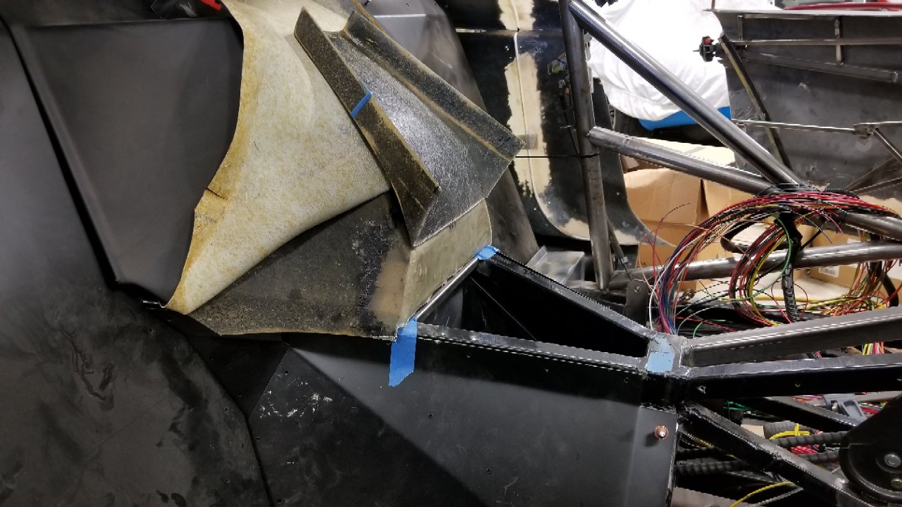
I started to mock up the 4" intake on #501 today. I found a supplier that has 90 deg and 45 deg bend 4" diameter tubes that are rated up to 250-275 degrees F. Plus they actually responded to a request email for confirmation of leg length and sketches within 24 hours. I will have to trim 1" to 2" off each section of tubing to get it to fit in there, but I think I can make that happen.
My only question, without putting the body on and checking (I have too much stuff piled all over it LOL), is in Pic 3. I'll have to rotate the 90 deg bend towards the front of the car and then add a bit of straight section before I put on a filter. I'd like to drop the filter right down near the side intake. Do you guys see any major clearance issues right here infant of the rear wheel or do you think I'll be ok here.
That's going to be super tight there. You would have to modify the aluminum close out/wheel well panels to get the tube thru there and the filter would pretty much be trapped between the body and alum panel. On builds like yours, I've been........let's see if I can find a pic....
Last edited by VRaptor SpeedWorks, LLC; 05-20-2020 at 10:35 PM.
Shane Vacek
VRaptor SpeedWorks, LLC www.vraptorspeedworks.com
Turn-key GTM, SL-C & Ultima GTR Built to Your Specs!
Offering a full line of GTM Upgrades and Custom Parts
That's going to be super tight there. You would have to modify the aluminum close out/wheel well panels to get the tube thru there and the filter would pretty much be trapped between the body and alum panel. On builds like yours, I've been........let's see if I can find a pic....
Thanks for the reply Shane, I see the issue now. I checked back in the manual and pulled the close out panel out and oh yea, right on top of where I'm thinking.
In your example above, how do you service the filter after everything is all buttoned up?
If I remember right, you can remove the bottom belly pan and pull it out the bottom. I agree that it's not in an ideal position, but also should not require much service unless you're putting thousands of miles per year on your GTM.....and it seems there's not that many people doing that. On cars with a lot of "stuff" in the engine bay, finding room for a 4" intake and filter gets challenging.
Shane Vacek
VRaptor SpeedWorks, LLC www.vraptorspeedworks.com
Turn-key GTM, SL-C & Ultima GTR Built to Your Specs!
Offering a full line of GTM Upgrades and Custom Parts
Thats the truth, its getting more challenging the more items I stuff in there and I bet most people aren't putting thousands of miles on a GTM.
I threw the close out panels up there to look at another option as well. I would get a short 5" stubby filter and it would be just behind the coolant tank. If I do this I'll definitely be going with side window scoops to pull more air in.
I think whoever was running the brake press on these closeout panels went a little overboard, they do not fit up at all LOL, I guess that's GTM problems.
Yes....the bends in those aluminum panels...the one directly in front of the wheel and small one forward of the shock mount.....we always take some of the bend out of those flanges. The horizontal bend that goes all the way across the large panel in front of the wheel...we usually take almost all of that bend out of the panel and beat it back flat. You do not want to fit/drill any of those panels until your body is positioned and then position the aluminum panels so that they support the body with the bulb seal.
Shane Vacek
VRaptor SpeedWorks, LLC www.vraptorspeedworks.com
Turn-key GTM, SL-C & Ultima GTR Built to Your Specs!
Offering a full line of GTM Upgrades and Custom Parts
Yup, right again had to rework the panels to get them to fit right, but sue to the routing of my CAI I will need to fabricate a closure to finish off the wheel well. I cut the FFR pieces down and reshaped them to allow the CAI tube to pass through where they would normally sit. And he square hole where it turns down to the filter is large enough to get filter in and out. Will make a 2 piece closure around the CAI tube to seal the filter off and as mentioned I will need to come up with one more piece to cover the tube that is exposed and seal off the wheel well against the body. Here is what the wheel looks like against the body before making the last pieces needed to seal it off:
Thanks for the response and pics James. Now that I have a better understanding of what I'm looking at here, I think I'm going to keep it easy and just get my filter over by my overflow tank.
On the PDG race GTM we made all the rear close out panels removable via Dzus fasteners. This allows us to access all those areas very easily. Like with the street GTMs, these areas are stuffed with coolers, filters, pumps, and tanks. You definitely want to be able to get in there after the initial build.
My thoughts on that......I can definitely see your point on your race car, where you have to constantly be removing panels in order to gain access to that stuff. On a street car like this, in my mind....how long is it going to take to figure out what Dzus fasterners to use, where are you going to order them from, how long is it going to take to receive them and then figure out where and how to install them...then actually install them and then install the panel?
Compare that to the 30 seconds it will take to drill all of the rivets out, pull the panel off and then take 5 minutes to install new rivets when you put the panel back in. I make the same argument in my mind when my customers want all of the panels held on with riv-nuts and screws. In the time it takes to pilot-drill all of the holes, then drill all of the holes in the chassis out for rivnuts, drill all of the holes out in the panel for screws, buy the rivnuts, install the rivnuts, put the panel on and use screws to secure it.....I could have drilled and and riveted the panel on 10x over.
Shane Vacek
VRaptor SpeedWorks, LLC www.vraptorspeedworks.com
Turn-key GTM, SL-C & Ultima GTR Built to Your Specs!
Offering a full line of GTM Upgrades and Custom Parts
Yes it does take a little longer...initially, but if it is for a constant service area like for an air cleaner...and you only do ONE appropriate panel, it is not much work. I do see your point and agree on riv nuts etc. for all the panels. Waste of time.
Four Dzus weld in backing plates and four captured Dzus plates and it is a done deal. I would argue that this is actually LESS work than to properly rivet in a panel. If the panel overlaps allow, you can get away with only one or two Dzuses.
Here are the backing plates at $2 each and fasteners at $2 each...
Thanks for the recommendations on fasteners and approach. I'll have to look them over a bit and get familiar with them to see if this would be something I'd like to incorporate.
It was a pretty productive 4 day weekend for me. I'm officially full blown into wiring on Shoeless GTM. I started off a week or so ago blowing apart the Vintage Air Harness that comes with the kit. The way it was laid out, just didn't fit where I wanted it, so once I fully understood where each wire needed to go, I just took it apart and installed it in the GTM where I needed it. I also have been using my label maker to ID each wire. I'm so glad I got this thing and have been using it, it makes it so easy to look at the instructions one, label it and then go to the garage and install it. Here is the Trinary Switch labeled and ready to install.
I then moved on to pulling all the power and ground wiring for the Infinitybox cells. I found that I will most defiantly need the InCode box from them to make some changes in the setup, but that's no big deal. I'll end up with what I want for my setup so I'm good with that. I though I was making nice progress on my large power cables until I remembered I needed to put in the windshield washer bottle. 3 steps forward 2 steps back. So I mocked that up and installed it to see what was in the way. I'm also leaving myself notes around the car so I know what needs to be ordered to finish this off (ground and power distribution blocks).
I then moved on to planning the location of the engine harness and chassis harness interface. I'll have a larger Deutsch AS connector, CAN Network Hub, and 6 Channel CAN Expansion Module that I need to put in. I have some CF left from the steering wheel so I'll use that and cut out a nice piece and mount it infant of the coolant lines in the tunnel.
Finally on Saturday night, I opened up my tuning software that I have for the AEM system I'm installing. AEM was nice enough to include an LS3 58X base map in the software so I at least have a starting point. This tune and setup will be highly modified to fit my wiring harness as I have changed many inputs and outputs, so I need to start to get familiar with the software. From what I'm seeing, I can set this up offline from the car, then upload it once I have power to the system. Wish me luck
I remember this part, just hope I can remember where all the wires went to and from .. LOL Really like that label system as I mentioned before I used flag labels I made but they can and do come off so if doing this again (building my own harness) I got to get me one of those machine like you have, looks like it is working well.
I remember this part, just hope I can remember where all the wires went to and from .. LOL Really like that label system as I mentioned before I used flag labels I made but they can and do come off so if doing this again (building my own harness) I got to get me one of those machine like you have, looks like it is working well.
I'm loving the Dymo Rhino 5200!!! Being able to label each circuit and then move on is perfect for me.
Took advantage of some Memorial Day sales and picked up the catch can I have had my eyes on for a bit from Motion Raceworks and also picked up an air oil separator to plumb between my valley cover and intake port. I took some 1/4" thick aluminum plate and made up some simple brackets to mount each item on the end of the heads. I think it turned out pretty nice. Now time to order up some fitting and start to run some plumbing.
I got to the point that I needed to coat and install the front close out panel so I could finally install the QRP front Sway Bar. I'm really starting to pack stuff in and run wiring to the front as well, so this panel was my next logical step. I didn't want to set up the Harbor Freight Car Port I bought last time to spray on bed liner on the majority of my panels, so I opted for the old Mendy shipping box. Not too bad, but you can see where my spray pattern wasn't perfectly smooth, but I think only I'll notice that. Once it cured it didn't look bad at all.
After curing for three days, the front panel was installed this morning and then the QRP Sway Bar.
The wiring also got some attention this morning now that I got my ground block installed next to the mega fuses. Starting to look a little more organized.
Shane Vacek
VRaptor SpeedWorks, LLC www.vraptorspeedworks.com
Turn-key GTM, SL-C & Ultima GTR Built to Your Specs!
Offering a full line of GTM Upgrades and Custom Parts
Got to spend some time in the garage this weekend. I had my eye on reinstalling the exhaust now that I got the brackets back from the powder coater, playing with the new LEDs, and then mounting some odds and ends.
I can't wait to actually fire this bad boy up to hear this exhaust!!! I ended up trying my non-cat pipes on both sides and I think I got it right the first time around. Although I know I'll have to likely reposition things once I get the body on, I was able to skew this off to the passenger side by about 1.5" per Shane's instructions, and they are dead level with my rear wing mount. How this will all line up with the body, I'll find out soon enough.
After that I was able to plug in a play with potential mounting locations of my 3 zone bluetooth controlled LED setup. I have to thank beeman for the recommendation of going with https://www.theretrofitsource.com. High quality products, the phone app for the Morimoto controller is on point, and its just bad a$$ . This setup is really nice and once the system is activated is starts out bright white, but when you open the app, you can do any color including some preprogrammed sequences. Even a nice red, white, and blue rolling sequence. So knowing this, I'll likely put a switch on the dash to turn these on and off and also put some type of door switch in so when the doors are open the LEDs are on as well. I tried a few areas, but I think I'll go with Zone 1 in the foot wells, Zone 2 on the top roll bar in the engine compartment, and Zone 3 maybe near the rear cage bars going to the rear shock mounts.
Then shifted to installing a carbon fiber plate that would hold my second CAN Network 4 port hub, 6 Channel CAN Network Expansion Port, and the Deutsch AS plug where the engine harness will interface with the vehicle harness. Conveniently I was able to mount this near the Vehicle Dynamics Module so it plugged right in with no extension cable needed. If I did this correctly, I should be able to still stick one cup holder in the rear close out if desired.
Looking good Sean, like the lights, mine have a remote for the engine bay and the hood area and one for the cockpit that is installed in cockpit or via blue tooth.
shoeless, this look good, but boy you have so much wiring and connections where it is hard to get to after car is all together.
The get the rear center out, you have to removed seat the two tank cover, before you can move get to anything there for any trouble shooting.
Thanks KGTM!!
I've pretty much run out of room on my passenger foot well and I'm trying to keep the drivers side a little cleared out for future items, so this was really my next spot to start stuffing things in. Not to mention the Vehicle Dynamics Module really needs to be at or near dead center of the car to give the proper feedback to make is useful. Where its at, it's only a few inches away from Fwd to Aft center. Also, thankfully with Deutsch DTM and Deutsch AS connectors the failure rates are so darn low that once I get everything up and running, I'm comfortable covering this all up. If something fails, then its time to open it up and fix it
That area is not really protected from the elements, is that an issue? I made a divider to keep road debris and water out of the tunnel.
Shouldn't be an issue with the sealed connectors I'll be using. I like what you did here with an easy access. I've had to stick 4 LED controller blocks in here as well, so maybe a good idea for me to do something similar to what you have here.
Looking for a little input here. I have lost one to many nights of sleep over this and thought I'd run it by everyone.
I'm not 100% happy with where my battery and all the stuff around it is ending up on my build. My main concern is where the positive terminal goes right next to the steering column. I even took the steering column apart and put some fuel hose around it. I've tried several ways to see if it would make me feel better, but the positive terminal is just darn close to it. I've tried flipping the battery around and putting the terminals on the other side, but its too close to other items. I've tried cutting away a little insulation on my tunnel coolant tubes to move them over more and scoot the battery over, but didn't like this. And several other ideas and just not happy. Here is what is currently looks like. In my head all I can think of is this battery grounding out and catching the car on fire.
My thought it to pick up some 1/4" thick aluminum plate and mount that across the frame rails that extend out from the center of the chassis and mount the battery high (see red outline below). I'd have to remake several cables and redo some wiring, but I think I would sleep better at night and the cables would come off the battery a lot nicer and in the orientation to even miss the aluminum cage that holds the battery in place. I did a little test fit of the front aluminum piece and checked if I can reach my heater hose shut off and those two items are clear. Is there anything I'm missing here and what do you guys think overall?


 Thanks:
  Likes:

Originally Posted by VRaptor SpeedWorks, LLC


 Reply With Quote