-
03-21-2021, 06:37 PM
#641

Originally Posted by
dlud

Congrats! What radiator are you using?
Thank you Sir!! I’m using a Dewitts C5 radiator and I also pick up their fan shroud.
-
Post Thanks / Like - 1 Thanks, 0 Likes
 dlud
dlud thanked for this post
-
03-21-2021, 08:18 PM
#642
Senior Member

Great to see you making big progress!
MK3.1 2004 Mach 1 donor. ABS, PS, TC.
GTM #304 LPE 525hp LS3
2000 C5 Lingenfelter LS1@489hp
1999 Corvette FRC/Z06 track car
-
03-23-2021, 06:30 AM
#643
Originally Posted by
beeman
Great to see you making big progress!
Thank you Sir!!!!
I've got some video of driving around the block to look through and a bunch of logged idle data I have been pouring over to see what to change next LOL. I should have logged some of my driving as I had an error in the DBW pedal, oh well another great excuse to cruise around the neighborhood 
-
03-28-2021, 07:28 AM
#644
-
03-29-2021, 08:26 AM
#645


Pic 2 is what you want aligned with the top corner of the chassis. You are correct in the fact that the license plate area is not vertical.....so a 90 degree bracket does not work. We always make our own bracket here from 14ga steel that covers most of the license plate area and bend it to an angle that matches the body. We attach the bracket to the license plate area and just let the bottom edge sit on the chassis while we move the body around on the chassis to get it aligned. Once we get the body aligned, we get in there with a 90 degree drill and pop a couple 1/8" holes thru the bracket into the chassis and cleco it in place. If you try to align the bracket to be square with with the back edge of the chassis instead of letting the bracket be where the body wants it to be...you end up with what you have going on there where it looks like the driver's side bolt is warping the body inboard.
Shane Vacek
VRaptor SpeedWorks, LLC
www.vraptorspeedworks.com
Turn-key GTM, SL-C & Ultima GTR Built to Your Specs!
Offering a full line of GTM Upgrades and Custom Parts
-
03-29-2021, 09:21 AM
#646
Originally Posted by
VRaptor SpeedWorks, LLC
Pic 2 is what you want aligned with the top corner of the chassis. You are correct in the fact that the license plate area is not vertical.....so a 90 degree bracket does not work. We always make our own bracket here from 14ga steel that covers most of the license plate area and bend it to an angle that matches the body. We attach the bracket to the license plate area and just let the bottom edge sit on the chassis while we move the body around on the chassis to get it aligned. Once we get the body aligned, we get in there with a 90 degree drill and pop a couple 1/8" holes thru the bracket into the chassis and cleco it in place. If you try to align the bracket to be square with with the back edge of the chassis instead of letting the bracket be where the body wants it to be...you end up with what you have going on there where it looks like the driver's side bolt is warping the body inboard.
Thanks for the reply Shane, I had a feeling I have this too high at the moment and will need to redo this step. Quite the PITA. I'll have to drop the exhaust down a bit before I reset this height, but I knew I would have to do this. Plus once I get the body centered I can center the exhaust as well. Then onto centering the wing mounts based off the exhaust location once I take the body back off.
Good catch on the drivers side bolt warping the body. Its was very minor out on the car, but once I took a pic with a flash and posted it here, it stuck out like a sore thumb and I immediately went out and loosened that bolt up. I'm a total newbie when it comes to working with fiberglass.
When I'm centering the body, is it more of a "flexing" of the rear part of the body or is there a sweet spot alignment wise where it will fall right in place? If I let the body rest on the rear without any force it's obviously more towards the driver's side. Seems like I need to get the left and right alignment held in place with a bracket with slots and then force the body to a level state.
-
03-29-2021, 10:21 AM
#647
I guess first off, you should have the passenger side of the body pulled up tight against the chassis tube at the front of the passenger door opening. That normally leaves about a 3/8" gap between the body and door striker bracket. We cut the door striker off the chassis, clamp it to the body and re-weld/tack it in place (then full-weld it once the body comes back off for paint). Doing this, instead of keeping the body tight to the striker, pulls the body toward the passenger side closer to where it needs to be.
We do both the centering and leveling based off the wheel arches. Measure from the coil-over mount out to the wheel arch to center it up and then with the suspension at full droop, measure from the hub up to the wheel arch on both sides to "level" it. We also use a level on the back of the body to verify that leveling the wheel arches to the suspension does not throw the rear of the body way out of whack.....and if so, we fudge things to an acceptable level....usually biased on getting the rear of the body level with the chassis. We do all of this with the body vice-gripped/clamped to the bracket and the bracket vice-gripped/clamped to the chassis. For side to side adjustments, we just loosen up the clamps to the chassis and let the bracket slide back and forth on the chassis tube. If we need to adjust the level, we loosen up the clamps to the body and twist the body and necessary to get it level. Once we have it where we want it, then we drill thru the body/bracket and cleco that and then drill thru the bracket/chassis tube and cleco that.
Shane Vacek
VRaptor SpeedWorks, LLC
www.vraptorspeedworks.com
Turn-key GTM, SL-C & Ultima GTR Built to Your Specs!
Offering a full line of GTM Upgrades and Custom Parts
-
03-29-2021, 09:55 PM
#648
Senior Member
Got a welder yet Sean? 
My rear bodywork is basically unchanged. I also welded up a support bracket to support the rearmost body at the back of the transmission subframe. I also cut the very rear off the subframe and rewelded to match the sorted out body position.
I'll add: I built my Cobra before I knew how to weld. I had multiple compromises because of it. ie bolting on components that should have been welded on, accepting things how they came from FFR, etc. Learning to weld was a very quick process, and opens up countless opportunities to the point that I would say learn to weld first, then build a car like this. Yes, it can be built as delivered but you WILL be compromising. You can do everything that Shane and I are recommending in these past 2 posts with a $100 Harbor Freight flux wire welder and the painted result will look excellent. Ideally you would want a MIG setup, but you are looking at $750+ after getting a gas bottle, and for little stuff like what you are trying to fix here, you don't need that. These are non-critical welds, I wouldn't go near the safety cage until you really know what you are doing.
Last edited by beeman; 03-30-2021 at 07:32 AM.
MK3.1 2004 Mach 1 donor. ABS, PS, TC.
GTM #304 LPE 525hp LS3
2000 C5 Lingenfelter LS1@489hp
1999 Corvette FRC/Z06 track car
-
03-30-2021, 08:20 AM
#649
Originally Posted by
beeman
Got a welder yet Sean?
My rear bodywork is basically unchanged. I also welded up a support bracket to support the rearmost body at the back of the transmission subframe. I also cut the very rear off the subframe and rewelded to match the sorted out body position.
I'll add: I built my Cobra before I knew how to weld. I had multiple compromises because of it. ie bolting on components that should have been welded on, accepting things how they came from FFR, etc. Learning to weld was a very quick process, and opens up countless opportunities to the point that I would say learn to weld first, then build a car like this. Yes, it can be built as delivered but you WILL be compromising. You can do everything that Shane and I are recommending in these past 2 posts with a $100 Harbor Freight flux wire welder and the painted result will look excellent. Ideally you would want a MIG setup, but you are looking at $750+ after getting a gas bottle, and for little stuff like what you are trying to fix here, you don't need that. These are non-critical welds, I wouldn't go near the safety cage until you really know what you are doing.
These are great points and I wish I would have picked up welding before I started the build. I would have easily been able to address a number of items. One of the sister companies to the one that I learned all the wiring from has kicked off a motorsports fabrication company with the same format of teaching. I ended up buying a VIP account so I have access to every class they currently offer and will offer in the future. With that, I'm going through their TIG welding class right now and really enjoying the content. Shane actually recommended to take a look at the TIG machine linked below at HF and so far I'm pretty impressed with the feedback it has. Plus one of my neighbor's kid is in a vocational path at school for welding and gave me some great feedback on this machine as well. I wish I would have done this earlier, but I'm seeing more and more things that will require cutting and welding to fix.
https://www.harborfreight.com/protig...can+tig+welder
-
03-30-2021, 09:26 AM
#650
Senior Member
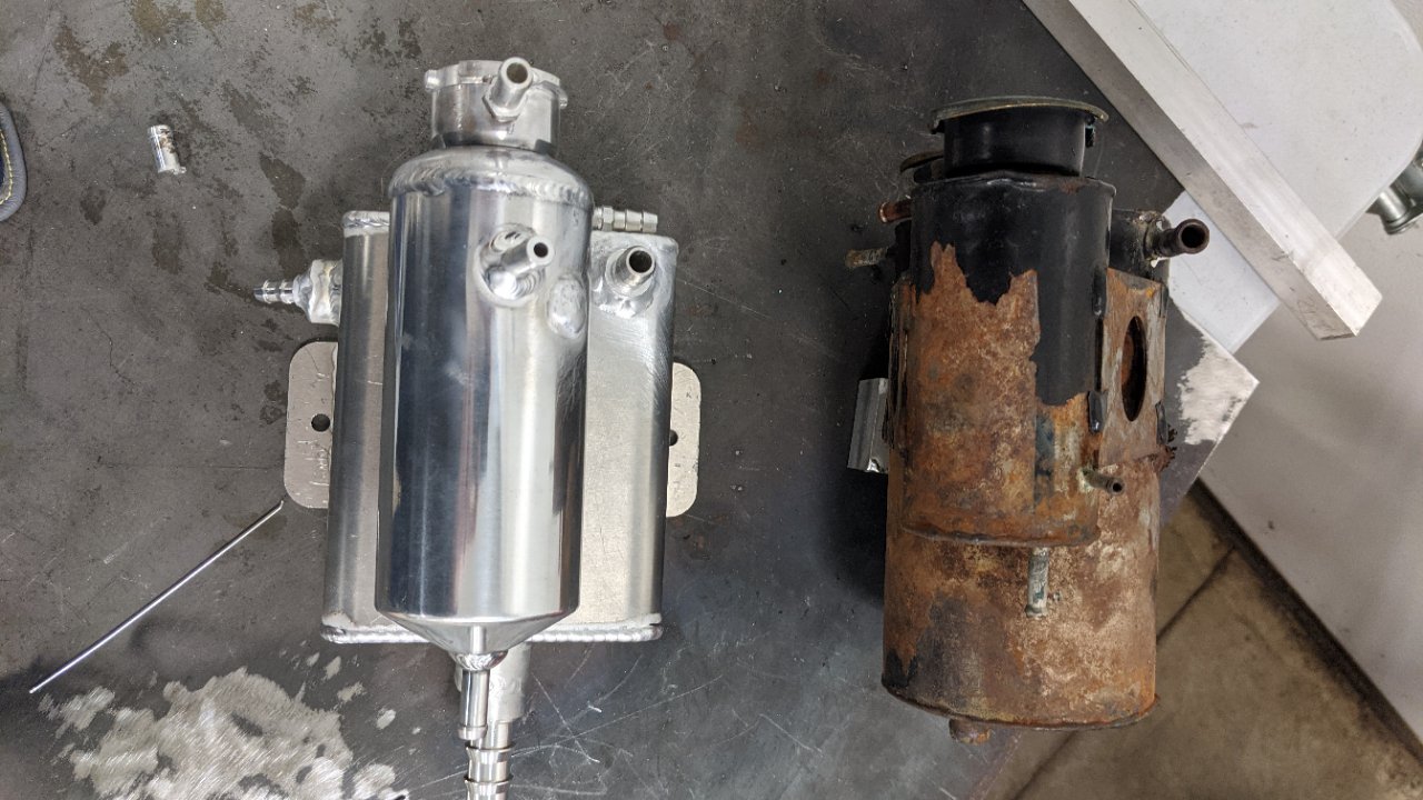
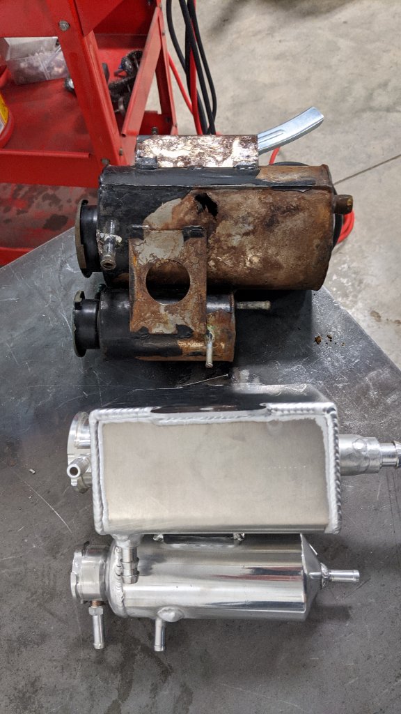
I actually just got a TIG machine and love it, the ability to weld aluminum and stainless opens even more options.
I got a Lotus Esprit Turbo, and the surge tank was on its last leg, corroded inside and out. I wanted to fab up my own out of aluminum, it's a dual tank system for engine cooling and chargecooler circuit. I got the TIG unit and played with it for a few hours, then went to town on the surge tanks. Not perfect, but I was impressed with what it could do with minimal practice. Will be a while before I'm stacking dimes (I didn't do those perfect tank welds, just some of the bungs and combining them into one unit).
I got this Primeweld unit based on reviews, especially customer service, and it has been great so far and can do 110/220. And I really like the TIG videos that WeldMetalsOnline has on Youtube, they recommended that unit.
https://weldmetalsonline.com/collect...-dc-tig-welder
Last edited by beeman; 03-30-2021 at 10:02 AM.
MK3.1 2004 Mach 1 donor. ABS, PS, TC.
GTM #304 LPE 525hp LS3
2000 C5 Lingenfelter LS1@489hp
1999 Corvette FRC/Z06 track car
-
Post Thanks / Like - 0 Thanks, 1 Likes
-
03-30-2021, 11:16 AM
#651
It's like anything else once you have the proper tool. You don't even think about it, you just solve the problem. Then, after awhile you find yourself looking back and wondering how you functioned without that tool.
"A grinder and paint makes me the welder I ain't!" LOL
Those tanks look really good. Especially if this is one of your first aluminum projects.
-
Post Thanks / Like - 0 Thanks, 1 Likes
-
03-30-2021, 11:38 AM
#652
Originally Posted by
beeman
I actually just got a TIG machine and love it, the ability to weld aluminum and stainless opens even more options.
I got a Lotus Esprit Turbo, and the surge tank was on its last leg, corroded inside and out. I wanted to fab up my own out of aluminum, it's a dual tank system for engine cooling and chargecooler circuit. I got the TIG unit and played with it for a few hours, then went to town on the surge tanks. Not perfect, but I was impressed with what it could do with minimal practice. Will be a while before I'm stacking dimes (I didn't do those perfect tank welds, just some of the bungs and combining them into one unit).
I got this Primeweld unit based on reviews, especially customer service, and it has been great so far and can do 110/220. And I really like the TIG videos that WeldMetalsOnline has on Youtube, they recommended that unit.
https://weldmetalsonline.com/collect...-dc-tig-welder
I came across that welder as well. Glad to get some good feedback on it. I've also got to get my electrician over to run me a 220 plug for welding and I mine as well put a 220 in for my wife's electric car charging. She just picked up a Chevy Bolt fully electric and it get about 250 miles per charge. I does ok on 110, but if totally drained it takes about 1.5 days to fully charge. Funny that I'm over here building the GTM with crazy V8 power and she has the all electric car. She has halfway convinced me to build her an all electric something next, so picking up welding and other fabrications skills will darn be mandatory.
@Shane:
1. After you get the body in a good spot and cleckoed in place, do you go back and bolt everything or just rivet it?
2. For the door striker on the passenger side. Do you cut the whole thing off the bottom square tube and also at the round vertical tube and then just slide it down the square tube until it butts up against the body? I image I'll have to add a piece to this bracket to be able to take up the gap I create between the vertical round tube and this striker bracket.
I appreciate you answering all my questions on this.
-
03-30-2021, 05:10 PM
#653
1. Normally, we just put about four 3/16" rivets thru the license plate area into the bracket in a square pattern (I cut the bracket tall so it covers most of the license plate area) and then 3 or so rivets thru the bracket into the chassis tube. That doesn't happen until the body is painted and final-installed. While we're working on the car, we just leave it cleco'd with 3/16" clecos once we get the body centered and leveled. PS....don't drill your rivet holes where your license plate holes are going to need to be!
2. We use a 4.5" angle grinder with cut-off wheel to cut the striker off flush with the top of the square tube as far as we can (basically just cutting thru the weld) and then use a sawzall to finish the cut since the grinder wheel will not go deep enough.....and we normally end up doing this with the body on because I always forget to do it until the body is already on and I always kind of hope that it won't need to be done....but it always does. We just cut it off right behind the striker itself where the narrow part of the rearward support is....we don't cut that whole support bracket off.....and then, yes, we cut a 5/16" or so wide chunk of steel to fill that gap between the striker and the support. Once it's cut off, we just use a spring clamp to clamp the striker to the body and then shift it around until the bottom lines up with the chassis where we want it and get a few really good tacks welded and the 5/16" chunk welded in so it can't bend or go anywhere. Once the body comes off for paint, then we full-weld the striker back to the tube and weld the back side of the gap-filler.
Shane Vacek
VRaptor SpeedWorks, LLC
www.vraptorspeedworks.com
Turn-key GTM, SL-C & Ultima GTR Built to Your Specs!
Offering a full line of GTM Upgrades and Custom Parts
-
03-31-2021, 05:12 PM
#654
Originally Posted by
VRaptor SpeedWorks, LLC
1. Normally, we just put about four 3/16" rivets thru the license plate area into the bracket in a square pattern (I cut the bracket tall so it covers most of the license plate area) and then 3 or so rivets thru the bracket into the chassis tube. That doesn't happen until the body is painted and final-installed. While we're working on the car, we just leave it cleco'd with 3/16" clecos once we get the body centered and leveled. PS....don't drill your rivet holes where your license plate holes are going to need to be!
2. We use a 4.5" angle grinder with cut-off wheel to cut the striker off flush with the top of the square tube as far as we can (basically just cutting thru the weld) and then use a sawzall to finish the cut since the grinder wheel will not go deep enough.....and we normally end up doing this with the body on because I always forget to do it until the body is already on and I always kind of hope that it won't need to be done....but it always does. We just cut it off right behind the striker itself where the narrow part of the rearward support is....we don't cut that whole support bracket off.....and then, yes, we cut a 5/16" or so wide chunk of steel to fill that gap between the striker and the support. Once it's cut off, we just use a spring clamp to clamp the striker to the body and then shift it around until the bottom lines up with the chassis where we want it and get a few really good tacks welded and the 5/16" chunk welded in so it can't bend or go anywhere. Once the body comes off for paint, then we full-weld the striker back to the tube and weld the back side of the gap-filler.
Awesome thanks for the tips!!!! Definitely delving into an area I've never worked in before.
-
04-03-2021, 09:53 AM
#655
-
Post Thanks / Like - 0 Thanks, 2 Likes
-
04-05-2021, 08:41 AM
#656
Sounds like it all worked out well! The bracket you made looks like it's almost identical to what I make here. One thing on fiberglass....you don't ever want to leave a sharp corner anywhere. Where you have the bottom corner of that license plate area cut square to the body.......if you look at the 4th photo down in your last post, the corner where the scale is, the corner is cut square and just above the scale is a tiny little saw cut. You're going to want to take a round file and round those corners out and get rid of that little saw cut to avoid having a crack start there and propagate out from there. Fiberglass is pretty picky that way. Always radius out all of your corners and try not to have any saw cuts like that left in the body anywhere. The bigger the radius you can get away with the better, but on the license plate area like that, we usually just use a 1/4" round file to finish out all of the corners.
A lot of the first GTM's built, we found out that over time, the body will crack out from the 2 top corners of the hatch opening for the same reason.....even with a large radius there, it is still a "corner" and stress point on the body.....so we cut some 14ga steel plates that match the profile of that corner and bond those plates to the bottom of the drip rail with panelbonding adhesive to reinforce the corner to prevent it from flexing and beginning a crack there.
Shane Vacek
VRaptor SpeedWorks, LLC
www.vraptorspeedworks.com
Turn-key GTM, SL-C & Ultima GTR Built to Your Specs!
Offering a full line of GTM Upgrades and Custom Parts
-
04-06-2021, 04:50 PM
#657
-
04-06-2021, 05:17 PM
#658
When we cut the bulb seal for the aluminum window panel, we leave long "tails" of the round bulb seal that will overhang the halo. Once we upholster and install the panel for the final time (before we put the painted body back on the chassis) we take superglue and glue the tail ends together so that the bulb seal is continuous all the way across the roof and down the sides. We have some really "squishy" foam rubber (bought from a lumberyard meant to seal up the rake of a pole building where the vertical steel and roof steel come together) that is about 2"x2", but takes next to no pressure to squish the 2" down to 1/4" thickness. We put a short strip of that on the engine bay side where the halo tubes meet the main "roll cage" tube above the front of the engine in order to help seal that area of the window panel. On the inside, we bevel/fit the hard foam roll bar pads to fit tight to the window panel and then when we wrap the halo in headliner, we but the headliner up against the window panel....so between all of that, it gets sealed up pretty tight.
Shane Vacek
VRaptor SpeedWorks, LLC
www.vraptorspeedworks.com
Turn-key GTM, SL-C & Ultima GTR Built to Your Specs!
Offering a full line of GTM Upgrades and Custom Parts
-
04-08-2021, 06:25 PM
#659
Originally Posted by
VRaptor SpeedWorks, LLC
When we cut the bulb seal for the aluminum window panel, we leave long "tails" of the round bulb seal that will overhang the halo. Once we upholster and install the panel for the final time (before we put the painted body back on the chassis) we take superglue and glue the tail ends together so that the bulb seal is continuous all the way across the roof and down the sides. We have some really "squishy" foam rubber (bought from a lumberyard meant to seal up the rake of a pole building where the vertical steel and roof steel come together) that is about 2"x2", but takes next to no pressure to squish the 2" down to 1/4" thickness. We put a short strip of that on the engine bay side where the halo tubes meet the main "roll cage" tube above the front of the engine in order to help seal that area of the window panel. On the inside, we bevel/fit the hard foam roll bar pads to fit tight to the window panel and then when we wrap the halo in headliner, we but the headliner up against the window panel....so between all of that, it gets sealed up pretty tight.
Awesome, thanks for the pointer on this!!! I came across a pic of one GTM that had the bulb seal all the way across the back window panel just like you mentioned the other day.
-
04-17-2021, 09:49 AM
#660
Not so much of an update other than sharing in typical GTM fashion, I was not happy with where I ended on the rear body alignment, and wondered if I could do better. I thought I had things pretty close, but when something keeps me up at night, I know I could do better. I knocked off work early yesterday and redid the rear body alignment.
I put the GTM back on the jack stands and shimmed it as close as possible with my large level and my laser level as I could get it left and right. From there I shimmed the body up once again and re-drilled the bracket one hole at a time checking my alignment up and down. After two holes were drilled through the license plate area, I started to bump the body towards the passenger side with a clamps holding it in place. After a little finesse my left and right was within 1/16" and height to wheel arches from the wheels is under 1/16" from side to side. I drilled the remaining holes double checking all my measurements along the way and I am WAY happier with the fitment now. From there I needed to readjust the exhaust tips to center them in the cut out areas and am very happy it was only a minor adjustment needed there.
Time to jump back to the interior area. I really want to get my harness bar, harness, and seats installed to make this thing somewhat safe and get into road tuning. Supposedly I can actually register it here in FL in this state, so once I get the seats installed I'll do that. Reading over some past posts and directions that Shane provided for locating the seats, it looks like I need to get the doors installed. I didn't think I would be jumping in on the doors this soon, but I guess its time to jump in head first. More notes from Shane on his first step of the doors is cutting the door frame. I've got some more research to do, plus I'm waiting for my welder to come in that I ordered. I decided to go with the Primeweld TIG225 that beeman recommended, but its on backorder until mid May. I'll work around this for now and get some odds and ends done.
-
04-18-2021, 05:51 PM
#661
Did some work on the interior yesterday. First up was fitting and mocking up the harness bar that Shane was nice enough to build for me. Pretty slick little design I will say. Bolts right in place instead of the shoulder strap for the seat belts. I need to get a couple longer bolts, but this thing fits perfectly. Now I need to really think about the color to powder coat it. I've done several brackets and my wildwood master cylinders in Silver Hammertone and I think I will carry this into the interior. For whatever reason this color seems to hold up a bit better to scratches and dings, compared to gloss black, so I think I'll stick with this color theme in the interior as well. It will also compliment the grey 5 point harnesses I found on Summit. Just need to order those up as well.


From here it was time to fit in the fuel tank covers. Per the manual and I think I have seen Shane mention it here that they need to be notched a bit to clear the door striker bracket. It wasn't much, but made some clearance on both covers and then set them in place. I think on the top where it will secure to the rear wall fits nice, same with the bottom into the floor frame. They seem to fit pretty well to the aluminum tunnel aluminum piece that's in the pic with the clecko holding it in place, but a bit of a gap to the next tunnel aluminum piece to the rear of that. From here the manual was a bit confusing on what gets installed first the tank covers or the engine cover. It seems to read that the tank cover would go first, but that didn't look right, so I put the tank covers on first and then rested the engine cover on top. Pretty decent fit on the tunnel aluminum, a bit of a gap between it and the last rear tunnel aluminum piece and then a large gap at the top where it would secure to the rear wall.
Can someone confirm what goes first, the tank covers or the engine cover?

-
04-19-2021, 08:28 AM
#662
The waterfall (engine cover) goes behind the tank covers. I usually get the tank covers all fitted and installed, then mark the inside and top edges of the tank covers onto the rear window panel with a sharpie. Pull the covers back out and then put the waterfall in place and get it to where it seems to fit the best with the top flange sitting level on the window panel. Once you get that positioned, transfer the tank cover marks to the top flange of the waterfall and mark the waterfall where the bottom edge of the window panel is. You will need to cut those corners off of the waterfall so that the tank covers and waterfall all sit flat against the window panel. When you trim the waterfall, be sure to allow a little bit of extra room for the upholstery....once you get the tank covers upholstered and the vinyl or leather wrapped back around the edge of the waterfall, that adds thickness you will have to account for. I usually extend the cuts down just a bit from where the waterfall hit the bottom edge of the window panel....maybe 1/2" or so. Of course, you will need to peel back the vinyl on the waterfall before you cut the corners back. You can peel it back a bit before you put it in place and make your marks, or mask it off, make your marks on the masking tape and then measure for how much you need to trim...then peel back and trim and re-cover the corners with the vinyl.
Shane Vacek
VRaptor SpeedWorks, LLC
www.vraptorspeedworks.com
Turn-key GTM, SL-C & Ultima GTR Built to Your Specs!
Offering a full line of GTM Upgrades and Custom Parts
-
04-19-2021, 09:17 AM
#663
Senior Member
Interesting... I didn't do it that way (yet). So will everything fit flush across the back once it's trimmed? Or do you still have a step off at the transitions from the aluminum firewall to the waterfall?
MK3.1 2004 Mach 1 donor. ABS, PS, TC.
GTM #304 LPE 525hp LS3
2000 C5 Lingenfelter LS1@489hp
1999 Corvette FRC/Z06 track car
-
04-19-2021, 01:10 PM
#664
All of the top flanges of the tank covers and waterfall where it bolts to the window panel sits pretty flush. The top edge of the waterfall is never quite exactly the same height as the tank covers, but as long as you get everything so it sits level on the window panel, it looks good. If you try to put the waterfall in front of the tank covers, it just doesn't fit well anywhere...it doesn't want to sit down on the window panel and won't fit right to the chassis....and you will have huge gaps at the transition where the tank covers, waterfall and chassis meet that will be open to the engine bay.
Shane Vacek
VRaptor SpeedWorks, LLC
www.vraptorspeedworks.com
Turn-key GTM, SL-C & Ultima GTR Built to Your Specs!
Offering a full line of GTM Upgrades and Custom Parts
-
04-19-2021, 02:00 PM
#665
Senior Member
Shane- so are you cutting the waterfall in the region of this yellow line to make it sit flush with the aluminum firewall? I just assumed you install it like Sean has in his picture. Surely FFR wouldn't have fully contact cemented the vinyl around the back of the waterfall?
CAU0C5i.jpg
Last edited by beeman; 04-19-2021 at 02:49 PM.
MK3.1 2004 Mach 1 donor. ABS, PS, TC.
GTM #304 LPE 525hp LS3
2000 C5 Lingenfelter LS1@489hp
1999 Corvette FRC/Z06 track car
-
04-19-2021, 04:01 PM
#666
Thanks for posting up the edited pic with proposed yellow cut line Dave, that was going to be my exact next clarification question
-
04-20-2021, 08:14 AM
#667
CAU0C5i_LI.jpg
No..you don't want to cut that whole edge off. That edge is what keeps the waterfall trapped behind the tank covers and "seals" that edge off from the engine bay. I only trim the top corner where the waterfall contacts the window panel and extend the cut down about 1/2" or so below the edge of the window panel so that the edge can "transition" from being flush with the tank covers to being behind the tank covers. That area in red buts up against the edge of the tank cover while the rest of that flange below rests against the back side of the tank cover.
Shane Vacek
VRaptor SpeedWorks, LLC
www.vraptorspeedworks.com
Turn-key GTM, SL-C & Ultima GTR Built to Your Specs!
Offering a full line of GTM Upgrades and Custom Parts
-
Post Thanks / Like - 1 Thanks, 0 Likes
-
04-20-2021, 08:24 AM
#668
Shane Vacek
VRaptor SpeedWorks, LLC
www.vraptorspeedworks.com
Turn-key GTM, SL-C & Ultima GTR Built to Your Specs!
Offering a full line of GTM Upgrades and Custom Parts
-
Post Thanks / Like - 1 Thanks, 0 Likes
-
04-20-2021, 08:36 AM
#669
Shane Vacek
VRaptor SpeedWorks, LLC
www.vraptorspeedworks.com
Turn-key GTM, SL-C & Ultima GTR Built to Your Specs!
Offering a full line of GTM Upgrades and Custom Parts
-
Post Thanks / Like - 1 Thanks, 0 Likes
-
04-20-2021, 10:58 AM
#670
Awesome Shane, thanks for the clarification and the photos!! Time to do a little trim and see if I can get this to fit up like you are showing.
-
05-05-2021, 02:26 PM
#671
-
Post Thanks / Like - 0 Thanks, 1 Likes
-
05-06-2021, 08:06 AM
#672
Shane Vacek
VRaptor SpeedWorks, LLC
www.vraptorspeedworks.com
Turn-key GTM, SL-C & Ultima GTR Built to Your Specs!
Offering a full line of GTM Upgrades and Custom Parts
-
05-23-2021, 10:30 AM
#673
-
05-23-2021, 01:42 PM
#674
Time to start roughing the doors in.
Shane,
I found some of your notes from prior posts on where you mention to cut the door frames in half. Before I go and screw this up, is this where you cut both square tubes in half?

-
05-30-2021, 06:57 PM
#675
OK so I have spent the last couple days working on the passenger door and either I am completely inept at this task or its just this much of a PITA for everyone. So I figure before I really screw something up, I better stop, take some pics, and ask some questions. First up was finding an answer to the last post. I keep in touch with a couple GTM owners and it just so happened that one of them had Shane do a lot of work on his GTM and he currently has his torn apart for some updates/fixes. I asked for a pic of the front frame of his doors and I see exactly how Shane cuts them and welds them up with extra square tube pieces. Here is that pic.
Pic 1

From here, I followed the instructions for how to locate and drill the holes on the front of the door for where the frame attaches to the door. At least I think I got it in the right place, I'll ask a series of questions after I post up my progress and other pics. From here I cut the openings for the hinge and door stop. The hinge pins are offset to one side and I originally put the offset to the inside. After plenty of frustration, I found a post from Shane noting the offset should be towards the outside. So I cut my openings larger to flip this part around.
Pic 2

I trimmed the body side for the clearance when the door opens per the manual and then tried to mount the door with the hinge pins on the car. This did not go so well LOL. Either I have the mounting holes in the wrong spot or there is a lot of clearance on the door edges that needs to be made to fit in the opening. I started to clearance the front top side of the door as it seems the front of the door needs to go up in the front. I shaved a bit back on the edge where the black sharpie is, but then stopped before I went too far.
Pic 3

At this point before I did more damage that I might have to repair later, I took the hinge out of the door and set the door in the car and looked at the inside gaps and they seem way off. There is a rather large gap at the back of the door and a very small gap at the front. This would lend me to believe I need to trim back the back edge of the door to physically move the door rearward in the opening. I also looked in the wheel well to see where my cut outs are in relation to the hinge pins and it looks way off. So either I have the cutouts in the wrong locations or the door needs to be raised in the front.
Pic 4

Pic 5

Pic 6

Pic 7

Questions:
1. Pic 2: Does the location of the holes on the front of the door in pic 1 look correct? I measured 1/2 inch from the bottom corner like the manual says, but the door just doesn't seem to fit in the opening. This could be entirely possible, but I wanted to confirm at least I have these in the right location.
2. Pics 3 - 7: If I have the holes that locate the door frame in the right place, and if my assumptions are correct that I need to move the door rearward and the front of the door up, how much do you guys normally see that has to get removed around the perimeter of the door to get it to fit in the opening properly? It looks like I need to remove about 1/4" off the rear edge and B-Piler to move the door back, and not sure how much I need to remove off the front top (pic 3 area).
-
06-01-2021, 10:41 AM
#676
Sorry...I've been tied up for the past several days trying to get a GTM finished here......just saw these posts this morning. I guess I'll just start at what I see would be the best place......
In Pic 6 and Pic 7, it looks like you need to get the main body pulled forward to be up tight against the frame tube that the hinges are welded to and also inboard to close up that big gap you see in Pic7. Make sure you have the wiper close-out box in place under the cowl of the main body, pull the bottom of the body inboard (below the door hinges) tight to that frame tube at the bottom and let the top part settle where it wants to. Measure from the large aluminum panels that are behind the front suspension out to the wheel arch of the main body to get the cowl of the main body centered on the chassis. If you try to pull the body tight to the chassis at the top part of that tube, it puts the body in a bind, so I usually just let that settle where it wants to be....as long as the wiper close-out box in in place under the cowl. Once you get the main body centered, drill and rivet the body to that tube that the hinges are welded to.
Looks like you have your hinge holes cut so that they line up with the hinges on the chassis. The door hinges need to sit on top of the chassis hinges, so you will need to move those up. I don't cut any holes in the door or mount anything to the door until I get the door fitted to the body like I want it to be. So once you're sure that you have the main body where it needs to be, I just keep test fitting the door to the body and grinding away whatever needs to be removed to get the door where I want it. Yes, in pic6, it looks like the front of the inner door is almost up against the body.......I normally have enough room there to put some 5/8" weatherstripping in there
....so....as long as you can move the door back without opening up a huge door gap on the outside of the door, I would start grinding material off the rear edge of the door to move the door back in the door opening. I try to keep the door so it fits exactly in the opening with zero door gap.....just keep test fitting the door to the body and grinding away the areas of contact until the door fits exactly how I want it to fit on the finished car. For the leading top edge of the door (pic3) where it meets the body, yes you will have to keep grinding away at the door until you can get it raised up AND moved inboard far enough so that when you open the door, that leading point will rotate behind the main body. Again, you want to just keep test fitting and marking where the door is tight and keep grinding off material until the door will go inboard far enough to make that happen.
Once the door is fitted perfectly to the body....THEN I put the door in place and wedge it/tape it/shim it/clamp it so that it is EXACTLY where I want it to be...as much of the door flush and aligned perfectly with the body as possible to get bodywork to a minimum. THEN I go to the front of the door thru the wheel well and mark where the door hinges need to come thru the door to sit on top of the hinges on the frame. This way, you are not using some arbitrary guesswork measurements to figure out where to cut the holes in the door....you can not un-cut the holes.....with the door perfectly fitted to the body, you can know exactly where the hinges need to come thru to sit perfectly on top of the chassis hinges.....make sure you account for the thickness of the hinge bushings.
This is the point where I cut the large weldment off the front of the door frame. I also weld reinforcement plates to the hinge bosses in the flat hinge plates to strengthen the hinges so they can't bend as easily. Cut the holes in the front of the door shell for the hinge plate to pass thru according to you marks. Now...more fun. If you test fit the 1/2" carriage bolts to the hinge plate, you will find that they don't go all the way tight against the plate.....the radius at the base of the square on the bolt binds up on the slot in the plate and holds the head of the carriage bolt out away from the plate. I take an angle grinder and cut-off wheel to square two sides of the bolt up so that the bolts sit flat against the plate and then use the angle grinder to score a small slot on the face of the threaded end of the bolt so I can tell which way to orient the bolt in the slot so my relief cuts in the bolt line up with the slot in the plate. The other problem with the carriage bolts is that the square of the carriage bolt is too high....it sticks up thru the flat hinge plate too far and engages with the slots in the door frame....and that's a very bad thing. Essentially, this will make it so that you will never keep your door adjustments because when you tighten the nut on the carriage bolt, all you're really doing is jamming the square of the carriage bolt up against the slot of the door frame and the flat hinge plate will be completely loose and your door will always fall out of adjustment on you.....so get the angle grinder back out and grind the top portion of that square on the carriage bolt to be round with the rest of the bolt.
Now you can put your carriage bolts thru the flat hinge plate, put the hinge plate thru the holes in the door and then put the front weldment of the door frame over the carriage bolts and install the washers and nuts. Now you can put your door back in the opening on the car and once again clamp/shim/tape it to fit perfectly in the body and get your hinge pins installed thru the hinges. Now you can position the door frame weldment where it needs to be on the door. Normally you will end up near the bottom of the adjustment slots in the hinge plate. Be sure to leave yourself some vertical adjustment in the slots, but if you move the door frame weldment up to the center of the hinge plate slots, it will be too high and your door speakers will hit the door frame....which they may regardless of what you do, but keeping the weldment positioned lower will help avoid this as much as possible. Since you should already have the door shell positioned perfectly where you want it, you shouldn't need much adjustment anyway. Now that you know where the door frame weldment needs to be, THAT is what will determine where to position the 5/16" carriage bolts and that aluminum trim plate that covers the front of the door behind the hinges. Again, position the holes for the 5/16" carriage bolts thru the weldment so that you have some adjustment in the slot to adjust the door in and out. Side note.....in order to get more/enough in/out adjustment for the front of the door, I normally have to trim the "tabs" off of the door frame weldment that end up hitting the door shell flange that the inner door panel mounts to.
Shane Vacek
VRaptor SpeedWorks, LLC
www.vraptorspeedworks.com
Turn-key GTM, SL-C & Ultima GTR Built to Your Specs!
Offering a full line of GTM Upgrades and Custom Parts
-
06-01-2021, 10:42 AM
#677
You will need to make a clearance cut in the main body for the leading edge of the door to tuck into/behind the body when the door opens. You can figure out how high up you need to go with the clearance cut by sighting down thru the door hinges on the chassis. At the intersection on the body where the hinge holes line up with the edge of the main body....that is how high the clearance cut needs to go. You will need to make that like part of the body like a knife-edge in order to clear the door while the door opens. Do not cut the door gap larger there to make room. Just thin the cut down to a knife edge.
That should take care of the front of the door. You should be able to hang the door, put in your hinge pins and open and close the door shell.
Now for the door latches. No need to cut that huge slot out of the fiberglass for the door striker. You already have the door fitted exactly how you want it, so you have no need for an inch of vertical adjustment. We normally cut the passenger striker plate off of the chassis and move it forward tight to the body and re-weld. Then find the exact center of the slot in the striker plate and drill an 1/8" hole thru the body. Now install your door, install the hinge pins, clamp/shim the rear of the door so it is in exact alignment with the body, reach in thru the window or thru the rear wheel well with a long 1/8" drill bit or sharpened rod and poke thru the 1/8" striker hole in the body...make sure you're holding it square to the striker plate and spin it up against the door shell enough to make a mark in the gel coat. THAT mark is the exact center of the latch with the latch closed. Now you know exactly where the latch needs to be installed. Since you are going to end up cutting your gel coat mark off when you cut the hole for the latch to fit in the door, I normally make an extended "crosshairs" mark before I start cutting so that even after the hole is cut in the door, I can still find the center of my mark with the extended horizontal and vertical marks on the door shell. with the latch hole cut in the door, now you know exactly where the latch mounting plate needs to be attached. Once you have that attached and the latch positioned so it is centered on the crosshairs with the latch closed, you can position your door frame inside the door.
Normally, the angle of the plate that the latch plate attaches to on the frame will not lay flat with the door frame, so we end up cutting that end of the door frame also. Normally we don't cut it all the way off the frame....just weaken it enough so we can bend it to match and lay flat against the latch plate. With the door laying flat on some stands or a table, lay the door frame inside the door and use the inner door panel to determine how high you can shim the door frame up before the door frame hits the inner door panel. The latch side of the door just bolts up to the latch plate, but the front of the door frame you want to shim up as far as you can without interfering with the inner door panel. Once you figure out where that point is, check how the latch end fits and bend the frame accordingly until the door latch plate sits flat against the door frame. Once that's done, you can bolt your latch end together and weld up the frame tubes at the front with some gussets like I did in Pic1.
Shane Vacek
VRaptor SpeedWorks, LLC
www.vraptorspeedworks.com
Turn-key GTM, SL-C & Ultima GTR Built to Your Specs!
Offering a full line of GTM Upgrades and Custom Parts
-
06-01-2021, 11:34 AM
#678
Hey Shane,
No need to apologies at all for any delays trying to get a car finished up at your shop. The pics of that finished up GTM are absolutely amazing!!!
I really appreciate you taking the time to post up these detailed instructions on how you approach the doors. I'll admit, I was completely lost and things just didn't look right so I thought it best to stop, step away, and reassess the situation. I'll get some good practice in repairing the areas of the doors I've already cut up trying to follow the lovely build manual.
Thanks again for posting this up, I'm sure I'll have some more questions along the way, but now I have at least an idea of what I need to go do for now.
-
06-02-2021, 05:57 PM
#679
-
06-03-2021, 08:38 AM
#680
That's all very common stuff that you're running into.
1. First 2 pics.....Ignore where that alum cowl panel placement was from FFR. You need to put bulb seal on your wiper box/close-out and get that under the cowl where it belongs. That will lift the cowl up where it needs to be. As a side note, we usually cut that wiper box in half and slide the two halves together a couple inches and rivet it back together so it's not so long (leave it the same height.....just shorten it length-wise) or you tend to run out of room in the top main alum panel that the wiper box sits on for the AC vent and defrost hoses to come up thru that panel because the wiper box is covering up the area that the hoses need to come up thru.
2. Pic 5 looks a TON better than it did before. We just make sure that the body is tight to the tube at the bottom (like you have it in pic 5) and sort of let the top part do what it wants....which is largely determined once you get the bulb seal on the wiper box and get it positioned under the cowl and the body centered by measuring from the alum right behind your sway bar mounts out to the wheel arch of the body on each side of the car to center the cowl up. Yes, we've had several cars where the halo is positioned too far to the right and prevents the body from moving inboard. Most are acceptable and as long as I think there will be enough room for the roll bar cover and headliner (we install headliner inside the A-pillar of the body), we leave it alone. There have been....I think 3 cars where the halo was so far to the RH side that we could not get the body where it needed to go and had to cut the base of the halo tube loose and move it inboard and re-weld. PITA, but much less so than trying to "work around" the fact that the body can't be centered.
3. Last pic....yes, we clamp that part of the body forward so that it is tight to the rear face of that square chassis tube all the way from the top to the bottom.
Shane Vacek
VRaptor SpeedWorks, LLC
www.vraptorspeedworks.com
Turn-key GTM, SL-C & Ultima GTR Built to Your Specs!
Offering a full line of GTM Upgrades and Custom Parts
-
Post Thanks / Like - 0 Thanks, 1 Likes
 dlud
dlud liked this post


 Thanks:
  Likes:


 Reply With Quote


